

Eaton DCF-3000 Installation Operation & Maintenance
DCF-3000 Installation, Operation & Maintenance
Description ......................................................................................... 1
Specifications ..................................................................................... 1
Service Requirements ................................................................... 1
Materials of Construction ............................................................... 1
Connections ................................................................................... 1
Elastomers ..................................................................................... 2
Solid Removal Limit ....................................................................... 2
Design Pressures .......................................................................... 2
Design Temperature ...................................................................... 2
Filter Volume.................................................................................. 2
Airborne Noise Emissions ............................................................. 2
Installation .......................................................................................... 2
Transportation................................................................................ 2
Securing to Foundation ................................................................. 2
Connecting to Process Piping ....................................................... 2
Checklist ........................................................................................ 2
Commissioning Procedure ............................................................ 2
Operation ............................................................................................ 3
Operational Modes ............................................................................. 3
Filtering .......................................................................................... 3
Screen Cleaning ............................................................................ 3
Purging .......................................................................................... 3
Inspection, Disassembly & Reassembly ............................................ 3
Spare Parts Lists ........................................................................... 5
Maintenance Schedule .................................................................. 6
Weekly ....................................................................................... 6
Monthly ...................................................................................... 6
Troubleshooting ................................................................................. 6
Symptoms ...................................................................................... 6
Possible Faults .............................................................................. 6
Warranty ............................................................................................. 7
Contacts ............................................................................................. 7
DOM0000007
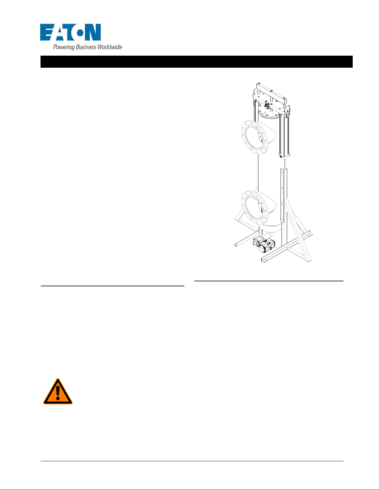
Description
Disc cleaned filter type DCF-3000 filter consists of a cylindrical 316
stainless steel filter screen sealed within a 316 stainless steel filter
vessel. Unfiltered process fluid under pressure enters the filter vessel
through the upper port. The process fluid enters the inside of the filter
screen from above and the filtrate flows through the screen, exiting
the filter vessel through the lower port. Contaminants are trapped on
the inside of the screen. The contaminants are periodically scraped
from the surface of the screen by two cleaning discs assemblies
which travels across the surface of the screen. These contaminants
are deposited in a collection chamber at the bottom of the filter vessel
where they are periodically purged out of the bottom port of the filter
vessel.
WARNING:
operate under specific pressure, temperature, and
other engineering parameters. There is a risk of
explosion, process fluid leakage or electrical shock if
the requirements set forth in this Manual are not
followed either during installation, operation, inspec tion or servicing of
this equipment. Equipment should be shut down and isolated from
energy sources and other equipment before any inspection or servicing
to prevent risk of shock or process fluid leakage. Appropriate PPE
required. FAILURE TO FOLLOW THIS WARNING MAY LEAD TO
DEATH, SEVERE INJURY OR PROPERTY DAMAGE.
Teflon® and Viton® are a trademarks of DuPont™. Nordel™ is a trademark of The Dow Chemical Company. Kynar® is a trademark of Elf Atochem North America, Inc.
®
is a trademark of Garlock Sealing Technologies LLC.
Gylon
DOM0000007, Revision A Page 1 of 7
This filter is a pressure vessel designed to
Specifications
The general specifications for a typical DCF-3000 filter system are:
Service Requirements
Electrical: None or 110-240 V AC 50/60 Hz based on controller type.
Air: Minimum 80 PSIG (5.51 bar), Maximum 116 PSIG (8 bar) at 5.0
cfm (141.5 L/min) clean, dry, non-lubricated air, connection size is ¼”
NPT.
Materials of Construction
All welded and wetted materials are type 316 STAINLESS STEEL.
WARNING: The material selection for this vessel is specified by the
customer. It is the customer’s responsibility to ensure material
compatibility with process and environment conditions.
SPECIFICATION OF INCOMPATIBLE MATERIALS MAY LEAD TO
PRODUCT FAILURE, LEAKAGE, DEATH, SEVERE INJURY OR
PROPERTY DAMAGE.
Connections
Process inlet & outlet: 8″ 150# ANSI raised face flange (standard) or
option ordered.
Purge: 2″ NPTI or option ordered.
DCF-3000 Installation, Operation & Maintenance
Elastomers
Lid actuator rod packing – Urethane, Teflon®, Viton® and Gylon®/
®
are available.
Viton
Lid upper and lower element elastomer – EPT, Viton
Nitrile (food grade) are available.
Cleaning disc blades – Delrin
®
and PEEK are available
®
and White
Solid Removal Limit
Process stream should contain no more than 500 PPM of strainable
solids by weight or volume (whichever is larger).
Design Pressures
Service: 150 PSIG (1035 kPa) maximum, 30 PSIG (207 kPa)
minimum.
Differential: Maximum differential pressure for slotted media is 50
PSID (345 kPa).
Design Temperature
Temperature limits vary based on process liquid, elastomers and
cleaning disc materials. Normally this temperature is limited to 200 °F
(93 °C).
WARNING: Do not operate filter with superheated
fluids (fluids that are above their boiling points at
atmospheric pressure). Operating the purge valve
with superheated fluids may result in a BLEVE
(boiling liquid expanding vapor explosion).
FAILURE TO FOLLOW THIS WARNING MAY LEAD TO DEATH,
SEVERE INJURY OR PROPERTY DAMAGE.
Filter Volume
Filter vessel: 48.8 US Gallons (185 L)
Purge chamber: 3.2 US Gallons (12 L)
Airborne Noise Emissions
<70dB (A) during normal operation
Installation
This document applies to the installation of the filter vessel. See
additional instructions for the installation of any filter unit controls.
Transportation
Move the filter system as close as possible to the installation site
before it is removed from the crate or skid. Position the filter frame on
a prepared, level foundation. Level the filter frame before it is
anchored to the foundation.
Securing to Foundation
Anchor the filter frame legs to the foundation using the six, 5/8″
diameter anchor holes located at the base of each frame leg.
Connect the stand grounding tab to a suitable earth ground point.
WARNING: Do not remove vessel from included
frame assembly. The unit is not intended to self-
FAILURE TO FOLLOW THIS WARNING
SEVERE INJURY OR PROPERTY DAMAGE.
Connecting to Process Piping
1. Attach the inlet and outlet connections to the interconnecting
piping (customer supplied). Take care to avoid excessive nozzle
loading at the filter connections. Consult your pump
manufacturers’ installation guide for minimum pipe run length
between the pump outlet and the inlet of the filter unit.
support by the process connections.
MAY LEAD TO DEATH,
Notice: Isolation/block valves (supplied by others) are
required on all process connections on the filter unit.
These valves allow the filter to be isolated from the
process liquid in the event that service is required.
Pressure gauges are also recommended on all
process connections.
2. Connect the drain line (customer supplied) to the filter unit purge
valve. To avoid restricting purge flow, the drain line should be: 1)
the same size as the purge valve or larger, 2) as short as
possible and 3) at or on a lower grade than the purge valve.
Checklist
Verify that all process connections are secure and free of leaks.
Check the condition of the filter element. It should be clean and
free of damage.
Confirm that the top and bottom element seals are installed
properly.
Confirm that proper element type be used, as process requires.
Confirm that the gasket sealing the lid to the filter housing is in
good condition and properly installed.
Check Star packing wheel and tighten as required. Urethane
seal requires only finger tight.
Confirm that the element hold-down plate and 3/8-16 socket
head cap screws are installed properly.
Verify that all lid bolts are tight. The lid bolt torque spec is 45 ft.-
lbs. Do not over tighten. Damage may occur to the lid O-ring and
flange surfaces if overtightened.
In its “home” position, the actuators of the filter should be
extended and the crossbar in the raised position.
Verify that the cleaning disc can be activated manually and
automatically if so equipped.
Verify that the purge valve is operable and normally in the
closed position for operation and start-up.
Check that the purge discharge line is directed in a suitable
fashion to accept waste when purged.
Check the safety switch is operable and functional. When
triggered, it should extend the actuators and put the crossbar in
the raised position.
Commissioning Procedure
1. Inspect the piping connections to the filter. Verify that the inlet
connection on the filter is connected to the pipe containing the
incoming process fluid. Repeat this procedure for the outlet and
purge connections.
2. All isolation valves to the filter should be closed. If there is a
bypass loop around the filter, that loop should be closed to
prevent back flushing dirty process fluid into the filter. Do not
stroke the cleaning disc actuators when isolation valves are
closed.
3. Open the isolation valve for the outlet piping.
4. If this filter is supplied with a control package, turn on the power
to the filter system controls.
5. Open the inlet isolation valve to allow approximately 25% of the
flow to reach the filter.
Notice: Opening the inlet valve to the fully open
position without proper ramping may cause particles to
become wedged into the filter screen. If this happens,
the screen will have to be removed and cleaned
manually.
6. Over the next ½ hour, slowly introduce more of the flow until you
reach 100%. You may want to manually initiate a purge during
this time to ensure that piping debris is cleaned from the unit.
DOM0000007, Revision A ` Page 2 of 7

DCF-3000 Installation, Operation & Maintenance
C
Operation
Notice: Do not exceed the normal operating
temperature of the lowest rated component. In most
cases this is 200 °F (93 °C).
1. The unit self-cleaning controls should be on whenever flow is
occurring through the filter. The controls should be off when
there is no flow.
2. The cleaning disc should stroke the filter element clean to keep
the differential pressure between the inlet and outlet of the filter
between 3 to 5 PSID (21 to 34 kPa). Stroking too frequently will
shorten the life of all wear components.
3. The filter unit is supplied with a valve used to purge the
contaminants from the vessel. This valve should be opened
before the collected contaminants exceed the purge chamber
volume and cause a differential pressure increase.
4. If the filter element is removed from the unit, avoid high pressure
washing from the inside of the element. This may force
contaminants into the filter media and cause permanent
blockage and/or element damage.
5. Always pressurize the unit slowly on startup and watch for leaks.
6. The unit is equipped with a 3/4″ port in the lid for placement of
overpressure vent, for use as an air release and/or connection
for fluid filing of vessel.
7. Monitoring of the differential pressure between the inlet and
outlet pressures should be used to determine stroking and
purging rates. Normal operation should exhibit low differential
pressure of 3-5 psi that is maintained continuously
Inspection, Disassembly & Reassembly
To service the unit: Isolate from process fluids, from the process air
and electric supply by using proper lockout tagout procedures.
Depressurize unit by opening purge and vent valve in that order and
de energize all sources of power.
Operational Modes
Filtering
Pressurized dirty process fluid enters thru the inlet port, passes
through the filter screen where contaminants are removed and clean
process fluid exits through the outlet port.
Screen Cleaning
The cleaning process occurs periodically during the filtering process.
As the dirty process fluid passes thru the filter screen, contaminants
are collected on the inside of the screen. The cleaning disc scrapes
the length of the element screen and pushes the contaminants into
the purge chamber.
Purging
The purging process occurs periodically during the filtering process.
The purge valve is opened, allowing the flow and pressure in the
vessel to push the concentrated contaminants collected in the purge
chamber out of the vessel.
AUTION: Do not backwash or operate the DCF-
3000 in any circumstance where flow can reverse
between the inlet and outlet ports. Backwashing
mechanically cleaned vessels may result in
damage to the element and cleaning disc
assemblies.
Figure 1
DOM0000007, Revision A ` Page 3 of 7
 Loading...