

Eaton DC1-122D3, DC1-S24D3, DC1-124D3, DC1-12011, DC1-322D3 Series Manual
...
Manual
10/12 MN04020003Z-EN
PowerXL
™
DC1
Frequency Inverter

All brand and product names are trademarks or registered trademarks of the owner
concerned.
Emergency On Call Service
Please call your local representative:
http://www.eaton.com/moeller/aftersales
or
Hotline of the After Sales Service:
+49 (0) 180 5 223822 (de, en)
AfterSalesEGBonn@eaton.com
Original Operating Instructions
The German-language edition of this document is the original operating manual.
Translation of the original operating manual
All editions of this document other than those in German language are translations of
the original German manual.
st
published 2012, edition date 10/12
1
© 2012 by Eaton Industries GmbH, 53105 Bonn
Production: René Wiegand
Translation: globaldocs GmbH
All rights reserved, including those of the translation.
No part of this manual may be reproduced in any form (printed, photocopy, microfilm
or any other process) or processed, duplicated or distributed by means of electronic
systems without written permission of Eaton Industries GmbH, Bonn.
Subject to alteration without notice.

Danger!
Dangerous electrical voltage!
Before commencing the installation
• Disconnect the power supply of the device.
• Ensure that devices cannot be accidentally restarted.
• Verify isolation from the supply.
• Earth and short circuit the device.
• Cover or enclose any adjacent live components.
• Follow the engineering instructions (AWA/IL) for the
device concerned.
• Only suitably qualified personnel in accordance with
EN 50110-1/-2 (VDE 0105 Part 100) may work on this
device/system.
• Before installation and before touching the device ensure
that you are free of electrostatic charge.
• The functional earth (FE, PES) must be connected to the
protective earth (PE) or the potential equalisation. The
system installer is responsible for implementing this
connection.
• Connecting cables and signal lines should be installed so
that inductive or capacitive interference does not impair
the automation functions.
• Install automation devices and related operating elements
in such a way that they are well protected against
unintentional operation.
• Suitable safety hardware and software measures should
be implemented for the I/O interface so that an open
circuit on the signal side does not result in undefined
states in the automation devices.
• Ensure a reliable electrical isolation of the extra-low
voltage of the 24 V supply. Only use power supply units
complying with IEC 60364-4-41 (VDE 0100 Part 410) or
HD384.4.41 S2.
• Deviations of the mains voltage from the rated value must
not exceed the tolerance limits given in the specifications,
otherwise this may cause malfunction and dangerous
operation.
• Emergency stop devices complying with IEC/EN 60204-1
must be effective in all operating modes of the automation
devices. Unlatching the emergency-stop devices must not
cause a restart.
• Devices that are designed for mounting in housings or
control cabinets must only be operated and controlled
after they have been installed and with the housing
closed. Desktop or portable units must only be operated
and controlled in enclosed housings.
Eaton Industries GmbH
Safety instructions
• Measures should be taken to ensure the proper restart of
programs interrupted after a voltage dip or failure. This
should not cause dangerous operating states even for a
short time. If necessary, emergency-stop devices should
be implemented.
• Wherever faults in the automation system may cause
injury or material damage, external measures must be
implemented to ensure a safe operating state in the event
of a fault or malfunction (for example, by means of
separate limit switches, mechanical interlocks etc.).
• Depending on their degree of protection, frequency
inverters may contain live bright metal parts, moving or
rotating components or hot surfaces during and
immediately after operation.
• Removal of the required covers, improper installation or
incorrect operation of motor or frequency inverter may
cause the failure of the device and may lead to serious
injury or damage.
• The applicable national accident prevention and safety
regulations apply to all work carried on live frequency
inverters.
• The electrical installation must be carried out in
accordance with the relevant regulations (e. g. with
regard to cable cross sections, fuses, PE).
• Transport, installation, commissioning and maintenance
work must be carried out only by qualified personnel
(IEC 60364, HD 384 and national occupational safety
regulations).
• Installations containing frequency inverters must be
provided with additional monitoring and protective
devices in accordance with the applicable safety
regulations. Modifications to the frequency inverters
using the operating software are permitted.
• All covers and doors must be kept closed during
operation.
• To reduce the hazards for people or equipment, the user
must include in the machine design measures that restrict
the consequences of a malfunction or failure of the drive
(increased motor speed or sudden standstill of motor).
These measures include:
– Other independent devices for monitoring safety-
related variables (speed, travel, end positions etc.).
– Electrical or non-electrical system-wide measures
(electrical or mechanical interlocks).
– Never touch live parts or cable connections of the
frequency inverter after it has been disconnected from
the power supply. Due to the charge in the capacitors,
these parts may still be live after disconnection. Fit
appropriate warning signs.
I

II

Table of contents
0 About this manual ..................................................................... 5
0.1 Target group................................................................................. 5
0.2 Writing conventions ..................................................................... 5
0.3 Abbreviations ............................................................................... 6
0.4 Mains supply voltages.................................................................. 7
0.5 Units............................................................................................. 7
1 DC1 device series ....................................................................... 9
1.1 Introduction .................................................................................. 9
1.2 System overview ......................................................................... 10
1.3 Checking the delivery................................................................... 11
1.4 Rated data .................................................................................... 13
1.4.1 Rating data on the nameplate ...................................................... 13
1.4.2 Key to part numbers..................................................................... 14
1.4.3 General rated operational data ..................................................... 16
1.4.4 Features ....................................................................................... 19
1.5 DC1 layout.................................................................................... 21
1.6 Features ....................................................................................... 22
1.7 Selection criteria........................................................................... 24
1.8 Proper use.................................................................................... 25
1.9 Maintenance and inspection ........................................................ 26
1.10 Storage......................................................................................... 26
1.11 Charging the internal DC link capacitors ...................................... 27
1.12 Service and warranty.................................................................... 27
2 Engineering................................................................................. 29
2.1 Introduction .................................................................................. 29
2.2 Electrical power network ............................................................. 30
2.2.1 Mains connection and configuration ............................................ 30
2.2.2 Mains voltage and frequency ....................................................... 31
2.2.3 Voltage balance ............................................................................ 31
2.2.4 Total Harmonic Distortion (THD) .................................................. 32
2.2.5 Idle power compensation devices ............................................... 33
2.2.6 Mains chokes ............................................................................... 33
2.3 Safety and switching.................................................................... 34
2.3.1 Fuses and cable cross-sections ................................................... 34
2.3.2 Residual current device (RCD) ..................................................... 35
2.3.3 Mains contactors.......................................................................... 36
2.4 EMC compliance .......................................................................... 36
DC1 Frequency Inverter 10/12 MN04020003Z-EN www.eaton.com 1

2.5 Motor and Application.................................................................. 38
2.5.1 Motor Selection ........................................................................... 38
2.5.2 Parallel connection of motors ...................................................... 38
2.5.3 Circuit types with three-phase motors......................................... 40
2.5.4 87-Hz Characteristic curve ........................................................... 40
2.5.5 Bypass operation ......................................................................... 42
2.5.6 Connecting EX motors................................................................. 43
2.5.7 Sinusoidal filter............................................................................. 43
2.5.8 Single-phase AC motors .............................................................. 45
2.5.9 Mode of operation of DC1-S2… frequency inverter .................... 47
3 Installation.................................................................................. 49
3.1 Introduction.................................................................................. 49
3.2 Mounting ..................................................................................... 49
3.2.1 Mounting position........................................................................ 50
3.2.2 Cooling measures ........................................................................ 50
3.2.3 Control panel installation.............................................................. 53
3.2.4 Fixing ........................................................................................... 55
3.3 EMC installation........................................................................... 58
3.3.1 EMC measures in the control panel............................................. 58
3.3.2 Earthing........................................................................................ 59
3.3.3 EMC screw .................................................................................. 60
3.3.4 VAR screw ................................................................................... 61
3.3.5 Shielding ...................................................................................... 61
3.4 Electrical Installation .................................................................... 63
3.4.1 Connection to power section....................................................... 64
3.4.2 Connection on control section ..................................................... 70
3.4.3 Block diagrams............................................................................. 78
3.4.4 Insulation test .............................................................................. 82
4 Operation.................................................................................... 83
4.1 Checklist for commissioning........................................................ 83
4.2 Operational hazard warnings........................................................ 84
4.3 Commissioning with control signal terminals (default settings) .. 85
5 Error messages .......................................................................... 89
5.1 Introduction.................................................................................. 89
5.1.1 Error Messages............................................................................ 89
5.1.2 Acknowledge fault (Reset)........................................................... 89
5.1.3 Error list........................................................................................ 91
2 DC1 Frequency Inverter 10/12 MN04020003Z-EN www.eaton.com

6 Parameters.................................................................................. 93
6.1 Operating unit .............................................................................. 104
6.1.1 Display unit................................................................................... 105
6.1.2 Menu Navigation .......................................................................... 105
6.1.3 Setting parameters....................................................................... 105
6.1.4 Parameter selection ..................................................................... 106
6.2 Digital and analog inputs .............................................................. 107
6.2.1 Digital Input (DI) ........................................................................... 108
6.2.2 Analog Input (AI)........................................................................... 109
6.2.3 Digital / analog outputs................................................................. 116
6.2.4 Drives control ............................................................................... 118
6.2.5 Second acceleration and deceleration time ................................. 119
6.2.6 frequency jump ............................................................................ 120
6.2.7 Start Function............................................................................... 121
6.2.8 Motor ........................................................................................... 123
6.2.9 Fixed frequency setpoint values .................................................. 125
6.2.10 V/f characteristic curve................................................................. 127
6.2.11 Braking ......................................................................................... 131
6.3 Operational data indicator ............................................................ 136
6.4 Setpoint input (REF) ..................................................................... 139
7 Serial interface (Modbus RTU).................................................. 141
7.1 General......................................................................................... 141
7.1.1 Communication ............................................................................ 141
7.1.2 Serial interface A-B....................................................................... 142
7.2 Modbus parameters..................................................................... 143
7.3 Operating mode Modbus RTU ..................................................... 144
7.3.1 Structure of the master request................................................... 145
7.3.2 Structure of the slave response ................................................... 146
7.3.3 Modbus: Register mapping.......................................................... 147
7.3.4 Explanation of function code........................................................ 153
8 CANopen..................................................................................... 155
8.1 Data Types ................................................................................... 155
8.2 System overview ......................................................................... 156
8.2.1 Bus termination resistors ............................................................. 157
8.2.2 Baud rate...................................................................................... 157
8.2.3 Set CANopen station address ...................................................... 158
8.2.4 Parameters that need to be configured ....................................... 158
8.3 Object list ..................................................................................... 159
8.3.1 EDS file ........................................................................................ 159
8.3.2 Communication-specific objects .................................................. 160
8.3.3 Server SDO Parameter................................................................. 161
8.3.4 Manufacturer-specific objects...................................................... 163
8.4 Error Messages............................................................................ 166
DC1 Frequency Inverter 10/12 MN04020003Z-EN www.eaton.com 3

9 Appendix..................................................................................... 167
9.1 Special technical data................................................................... 167
9.1.1 DC1-1D ........................................................................................ 167
9.1.2 DC1-S2......................................................................................... 168
9.1.3 DC1-12......................................................................................... 168
9.1.4 DC1-32......................................................................................... 169
9.1.5 DC1-34......................................................................................... 169
9.2 Dimensions and frame size.......................................................... 170
9.3 PC interface card.......................................................................... 171
9.3.1 DX-COM-STICK............................................................................ 171
9.3.2 drivesConnect.............................................................................. 173
9.4 Cables and fuses.......................................................................... 174
9.5 Mains contactors ......................................................................... 177
9.6 Braking resistances...................................................................... 179
9.7 Mains chokes............................................................................... 180
9.8 Motor reactors ............................................................................. 182
9.9 Sinusoidal filter............................................................................. 184
4 DC1 Frequency Inverter 10/12 MN04020003Z-EN www.eaton.com

0 About this manual
0.1 Target group
0 About this manual
0.1 Target group
This manual contains special information required for the correct selection
and connection a DC1 frequency inverter and its configuration to your specific requirements using the parameters. The details apply to the indicated
hardware and software versions. The manual describes all sizes of the DC1
device series. The differences and special characteristics of each rating level
and size are listed accordingly.
The content of MN04020003Z-EN manual is written for engineers and electricians. A specialist knowledge of electrical engineering and fundamental
technical principles is needed for commissioning.
We assume that you have a good knowledge of engineering fundamentals
and that you are familiar with handling electrical systems and machines, as
well as with reading technical drawings.
0.2 Writing conventions
Symbols used in this manual have the following meanings:
Indicates instructions to be followed.
Indicates useful tips.
→
NOTICE
Warns about the possibility of material damage.
CAUTION
Warns of the possibility of hazardous situations that may possibly cause slight injury.
DANGER
Warns of hazardous situations that result in serious injury or
death.
For greater clarity, the name of the current chapter and the name of the current section are shown in the page header.
DC1 Frequency Inverter 10/12 MN04020003Z-EN www.eaton.com 5

0 About this manual
0.3 Abbreviations
0.3 Abbreviations
→
included in this manual, the housing of the frequency inverter,
as well as other safety-relevant parts, have been left out. However, it is important to note that the frequency inverter must
always be operated with its housing placed properly, as well as
with all required safety-relevant parts.
All the specifications in this manual refer to the hardware and
In order to make it easier to understand some of the figures
→
software versions documented in it.
More information on the devices described here can be found
→
on the Internet under:
http://www.eaton.com/moeller
Support
The following abbreviations are used in this manual.
dec Decimal (base-10 numeral system)
DS Default settings
EMC Electromagnetic compatibility
FE Functional earth
FS Frame Size
FWD Forward run (clockwise rotating field)
GND Ground (0-V-potential)
hex Hexadecimal (base-16 numeral system)
ID
IGBT Insulated gate bipolar transistor
LCD Liquid Crystal Display
LSB
MSB
PDS
PE Protective earth
PES EMC connection to PE for screened lines
PNU Parameter number
REV Reverse run (anticlockwise rotation field active)
ro Read Only (read access only)
rw Read/Write (read/write access)
UL Underwriters Laboratories
Identifier (unique ID)
Least significant bit
Most significant bit
Power Drive System (magnet system)
6 DC1 Frequency Inverter 10/12 MN04020003Z-EN www.eaton.com

0.4 Mains supply voltages
0 About this manual
0.4 Mains supply voltages
The rated operating voltages stated in the following table are based on the
standard values for networks with a grounded star point.
In ring networks (as found in Europe) the rated operating voltage at the transfer point of the power supply companies is the same as the value in the consumer networks (e.g. 230 V, 400 V).
In star networks (as found in North America), the rated operating voltage at
the transfer point of the utility companies is higher than in the consumer network.
Example: 120 V 115 V, 240 V 230 V, 480 V 460 V.
The DC1 frequency inverter's wide tolerance range takes into account a permissible voltage drop of 10% (i.e. U
it takes into account the
North American mains voltage of 480 V + 10 %
(60 Hz).
The permissible connection voltages for the DC1 series are listed in the
Technical Specifications section in the appendix.
- 10%) while, in the 400-V category,
LN
0.5 Units
The rated mains voltage operational data is always based on mains frequencies of 50/60 Hz within a range of 48 to 62 Hz.
Every physical dimension included in this manual uses international metric
system units, otherwise known as SI (Système International d’Unités) units.
For the purpose of the equipment's UL certification, some of these dimensions are accompanied by their equivalents in imperial units.
Table 1: Unit conversion examples
designation
Length 1 in (’’) 25.4 mm 0.0394 inch
Power
Torque
Temperature 1°F (TF) -17.222 °C (TC) TF=TC×9/5+32 Fahrenheit
Speed
Weight 1lb 0.4536 kg 2.205 pound
US-American value SI value Conversion value US-American
designation
1HP=1.014PS 0.7457 kW 1.341 horsepower
1 lbf in 0.113 Nm 8.851 pound-force inches
1rpm 1min
-1
1 Revolutions per minute
DC1 Frequency Inverter 10/12 MN04020003Z-EN www.eaton.com 7

0 About this manual
0.5 Units
8 DC1 Frequency Inverter 10/12 MN04020003Z-EN www.eaton.com

1 DC1 device series
1.1 Introduction
1 DC1 device series
1.1 Introduction
DC1 series frequency inverters are ideally suited to applications involving the
simple frequency control of three-phase motors within an output range of
0.37 kW (at 230 V) to 11 kW (at 400 V) and AC motors within an output range
of 0.37 to 1.1 kW (at 230 V).
DC1 series devices feature a compact and rugged design and are available in
three sizes (FS1, FS2, FS3), as well as with protection types IP20 and IP66.
For protection type IP66, there is also a model with a mains switch and controls for local control available.
Due to their ease of use and handling, the innovative technology behind
them, and a high level of reliability, DC1 frequency inverters are particularly
suitable for use in general applications. In addition, an integrated radio interference suppression filter and a flexible interface ensure that the inverters
meet a number of important needs in the machine building industry when it
comes to the optimization of production and manufacturing processes.
The computer-supported parameter configuration software ensures data
integrity and reduces the time required for commissioning and maintenance.
In addition, the comprehensive accessories available increase the inverters'
flexibility in all areas of application.
DC1 frequency inverter 10/12 MN04020003Z-EN www.eaton.com 9
1 DC1 device series
Ready
I
O
A
⏚
L1/L
L2/N
L3
⏚
U
V
W
1
2
3
4
5
6
7
8
9
10
11
⑤
④
⑥
①
②
③
⑦
1.2 System overview
1.2 System overview
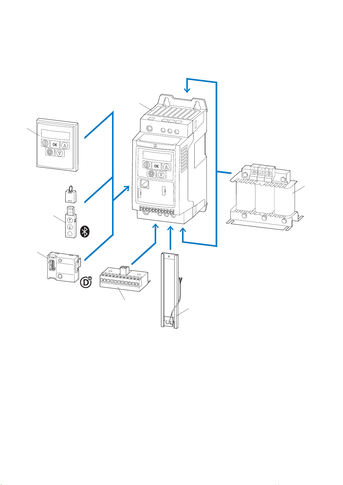
Figure 1: DC1 frequency inverters system overview
a DC1-… frequency inverters
b DX-LN-… main chokes, DX-LM3-… motor reactors, DX-SIN3-… sinusoidal filters
c DX-BR… braking resistance
d DXC-EXT-… expansion module
e DXC-NET-… fieldbus connection
f DX-COM-STICK communication module and accessories (e. g. DX-CBL-… connection cable)
g DE-KEY-… keypad (external)
10 DC1 frequency inverter 10/12 MN04020003Z-EN www.eaton.com

1.3 Checking the delivery
1 DC1 device series
1.3 Checking the delivery
→
⏚
1
2
3
4
⏚
Figure 2: Location of nameplate on DC1 frequency inverter
make sure that you received the correct frequency inverter.
L1/L
L2/N
L3
5
6
7
8
9
10
11
U
V
W
The DC1 series frequency inverters are carefully packaged and prepared for
delivery. The devices should be shipped only in their original packaging with
suitable transportation materials. Please take note of the labels and instructions on the packaging, as well as of those meant for the unpacked device.
Before opening the package, please check the label on it to
Open the packaging with adequate tools and inspect the contents immediately after receipt in order to ensure that they are complete and undamaged.
DC1 frequency inverter 10/12 MN04020003Z-EN www.eaton.com 11
1 DC1 device series
⏚
L1/L
L2/N
L3
⏚
U
V
W
1
2
3
4
5
6
7
8
9
10
11
1.3 Checking the delivery
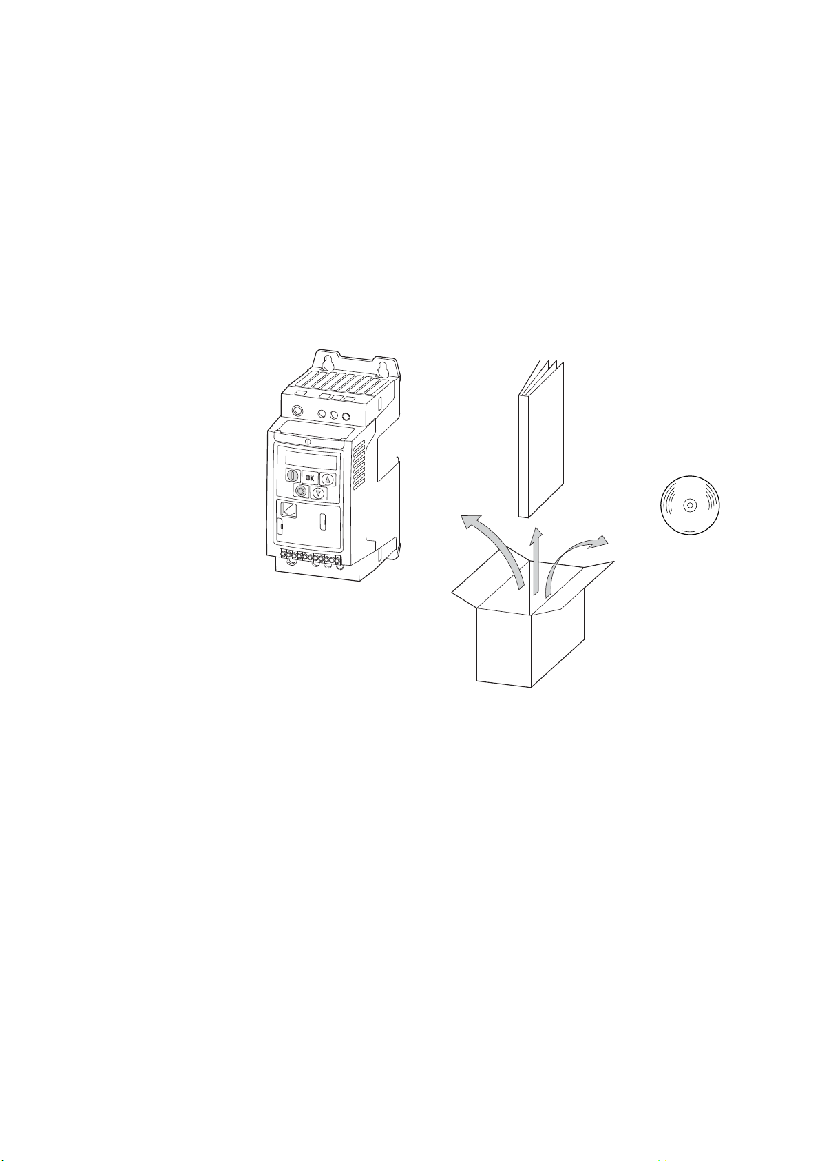
The packaging must contain the following parts:
• DC1 series frequency inverter,
• an instructional leaflet
• IL04020009Z,
• IL04020013Z for devices with protection type IP66
• IL04020014Z for DC1-S2… series frequency inverters for
single-phase AC motors
• A data carrier (CD-ROM) containing documentation for DC1 series fre-
quency inverters
IL
Figure 3: Equipment supplied with DC1 frequency inverter
CD
12 DC1 frequency inverter 10/12 MN04020003Z-EN www.eaton.com

1.4 Rated data
a
Voltage categories
DC1 frequency inverters are divided into following voltage categories:
• 110 V: DC1-1D…
• 230 V: DC1-12…, DC1-S2…, DC1-32…
• 400 V: DC1-34…
1.4.1 Rating data on the nameplate
The device-specific rated operational data for the DC1 frequency inverter is
listed on the nameplate on the right side of the device.
The inscription of the nameplate has the following meaning (example):
Inscription Meaning
1 DC1 device series
1.4 Rated data
DC1-344D1FB-A20N Part no.:
Input
Output
Power
S/N
IP20/Open type
25072012
DC1 = DC1 series frequency inverter
3 = Three-phase mains connection / three-phase motor connection
4 = 400 V mains voltage category
4D1 = 4.1 A rated operational current (4-decimal-1, output current)
F = Integrated radio interference suppression filter
B = Integrated brake chopper
A = LED display (7-segment text display)
20 = IP20 protection type
N = Standard basic device
Power connection rating:
Three-phase AC voltage (U
380 - 480 V voltage, 50/60 Hz frequency, input phase current (5.1 A).
Load side (motor) rating:
Three-phase AC voltage (0 - U
output frequency (0 - 500 Hz)
Assigned motor output:
1.5 kW at 400 V/2 HP at 460 V for a four-pole, internally cooled or surface-cooled
three-phase asynchronous motor (1500 min
Serial number
Frequency inverter is an electrical apparatus.
Read the manual (in this case MN04020003Z-EN) before making any electrical
connections and commissioning.
Protection type of the housing: IP 20, UL (cUL) Open type
Manufacturing date: 25.07.2012
3~ AC),
e
), output phase current (4.1 A),
e
-1
at 50 Hz/1800 rpm at 60 Hz)
DC1 frequency inverter 10/12 MN04020003Z-EN www.eaton.com 13

1 DC1 device series
1.4 Rated data
1.4.2 Key to part numbers
The catalog no. or part no. for the DC1 series of frequency inverters is made
up of four sections.
Series – Power section – Model – Version
The following figure shows it in greater detail:
D C 1 - 1 2 4 D 1 F N - A 2 0 N Explanation
Type
N = Standard basic device
Protection type
20 = IP20 / NEMA 0
66 = IP66 / NEMA 4X
6S = IP66 with switch / NEMA 4X, switched
Display unit (display)
A = LED display
B = OLED display
Brake Chopper
N = No internal brake chopper
B = Brake chopper
EMC (radio interference suppression filter)
N = No internal RFI filter
F = Internal RFI filter
Rated operational current (examples)
2D2 = 2.2 A
4D1 = 4.1 A
024 = 24 A
Mains voltage category
1 = 110 V (110 - 115 V ±10 %)
2 = 230 V (200 - 240 V ±10 %)
4 = 400 V (380 - 480 V ±10 %)
D = 110 V input / 230 V output (voltage doubler)
Connection in power section
1 = Single-phase mains connection / three-phase motor connec 3 = Three-phase mains connection / three-phase motor connec-
S = Single-phase mains connection / single-phase motor
Device series
DC1 = Frequency inverter, compact, Series 1
(D = Drives, C = Compact, 1 = Series)
Figure 4: Key to part numbers of the DC1 frequency inverters
14 DC1 frequency inverter 10/12 MN04020003Z-EN www.eaton.com

Catalog number examples
Inscription Meaning
1 DC1 device series
1.4 Rated data
DC1-124D1FN-A20N DC1 = DC1 series frequency inverter
DC1-S27D0FB-A20N DC1 = DC1 series frequency inverter
DC1-34024NB-A20N DC1 = DC1 series frequency inverter
DC1-342D2FN-A6SN DC1 = DC1 series frequency inverter
1) Standard version = with Modbus
2) For frequency inverters without an internal EMC filter, external measures for complying with the relevant limits
concerning electromagnetic compatibility (EMC) must be taken for operation as per IEC/EN 61800-3
(e.g., external radio interference suppression filter).
1 = Single-phase mains connection / three-phase motor connection
2 = 230 V mains voltage category (200 - 240 V ±10 %)
4D1 = 4.1 A rated operational current (output current)
F = Internal radio interference suppression filter (RFI, EMC measure)
N = No internal brake chopper
A = LED display (7-segment) on operating unit
20 = Protection type IP20 / NEMA 0
N = Standard basic device
S = Single-phase mains connection / single-phase motor connection for AC motors
2 = 230 V mains voltage category (200 - 240 V ±10 %)
7D0 = 7 A rated operational current (output current)
F = Internal radio interference suppression filter (RFI, EMC measure)
B = Internal brake chopper. An external braking resistor (optional) is required for this
function.
A = LED display (7-segment) on operating unit
20 = Protection type IP20 / NEMA 0
N = Standard basic device
3 = Three-phase mains connection / three-phase motor connection
4 = 400 V mains voltage category (380 - 480 V ±10 %)
024 = 24 A rated operational current (output current)
N = No internal radio interference suppression filter (RFI)
B = Internal brake chopper. An external braking resistor (optional) is required for this
function.
A = LED display (7-segment) on operating unit
20 = Protection type IP20 / NEMA 0
N = Standard basic device
3 = Three-phase mains connection / three-phase motor connection
4 = 400 V mains voltage category (380 - 480 V ±10 %)
2D2 = 2.2 A rated operational current (output current)
F = Internal radio interference suppression filter (RFI, EMC measure)
N = No internal brake chopper
A = LED display (7-segment) on operating unit
6S = Protection type IP66 / NEMA 4X with switches (mains switch, enable/phase
sequence, potentiometer) for local control
N = Standard basic device
1)
1)
2)
1)
1)
→
DC1 frequency inverter 10/12 MN04020003Z-EN www.eaton.com 15
DC1… N… for operation as per IEC/EN 61800-3.
An external radio interference suppression filter is required for

1 DC1 device series
1.4 Rated data
1.4.3 General rated operational data
Technical Data Formula
sign
General
Standards EMC: EN 61800-3:2004+A1-2012
Certifications and manufacturer's declarations on conformity CE, UL, cUL, c-Tick
Production quality RoHS, ISO 9001
Climatic proofing ρ
Ambient air temperature
Operation
IP20 (NEMA 0) ϑ °C -10 - +50 (frost-free and condensation-free)
IP66 (NEMA 4X) ϑ °C -10 - +40 (frost-free and condensation-free)
Storage ϑ °C -10 - +60
Electrostatic discharge (ESD, EN 61000-4-2:2009 V kV ±4, contact discharge
Fast transient burst (EFT/B, EN 61000-4-4: 2004) V kV ±1, at 5 kHz, control signal terminal
Overvoltage (surge, EN 61000-4-5: 2006)
110 - 115 V, 200 - 240 V V kV ±1, phase to phase/neutral conductor
380 - 480 V V kV ±2, phase to phase
Dielectric strength (flash, EN 61800-5-1: 2007)
110 - 115 V, 200 - 240 V V kV 1.5
380 - 480 V V kV 2.5
Radio interference class (EMC)
Category and maximum screened motor cable length
C1 l m 1, only with sizes FS1 and FS2 for single-phase
C2 l m 5
C3 l m 25
Mounting position Vertical, max. ±30 °
Altitude H m 0 - 1000 above sea level,
Degree of protection IP20 (NEMA 0) / IP66 (NEMA 4X)
Busbar tag shroud BGV A3 (VBG4, finger- and back-of-hand proof)
w
Unit Value
Radio interference: EN 55011: 2010
Safety: EN 61800-5: 2007
Protection type: EN 60529: 1992
% < 95 %, average relative humidity (RH),
non-condensing (EN 50178)
-10 - +45 for DC1-12011… and DC1-32011…,
for UL compliance over a period of 24 hours
±8, air discharge
±2, at 5 kHz, motor connection terminals,
single-phase mains connection terminals
±4, at 5 kHz, three-phase mains connection terminals
±2, phase/neutral conductor to earth
±4, phase to earth
mains voltages (110 - 115 V, 200 - 240 V)
> 1000 with 1% load current reduction every 100 m,
maximum 2000 with UL approval,
maximum 4000 (without UL)
16 DC1 frequency inverter 10/12 MN04020003Z-EN www.eaton.com

1 DC1 device series
1.4 Rated data
Technical Data Formula
sign
Main circuit / power section
Power supply system
Rated operational voltage
DC1-1D… U
DC1-S2…, DC1-12… U
DC1-32… U
DC1-34… U
e
e
e
e
Mains frequency f Hz 50/60 (48 Hz - 62 Hz)
Power factor p.f. >98
Phase Imbalance % max. 3
Maximum short-circuit current (supply voltage) I
q
Mains switch-on frequency Maximum of one time every 30 seconds
Mains network configuration (AC power supply
network)
Motor feeder
Output voltage
DC1-1D… U
DC1-S2… U
DC1-12…, DC1-32…, DC1-34… U
2
2
2
Output Frequency
Range, parameterizable f
2
Resolution Hz 0.1
Overload current
for 60 s % 150
for 2 s % 175
Pulse frequency
FS1 f
FS2, FS3 f
PWM
PWM
Operating mode V/Hz control, slip compensation
DC braking
Time before start t s 0 - 25, at stop, only with size FS1
Motor pick-up control function (for catching spinning
motors)
Brake chopper only for sizes FS2 and FS3
Braking current during continuous operation % 100 (Ie)
Maximum braking current % 150 for 60 s
Unit Value
V 1~ 110 (110 V - 0 % - 115 V +10 %, → U2 = 230 V)
V 1~ 230 (200 V -10 % - 240 V +10 %)
V 3~ 230 (200 V -10 % - 240 V +10 %)
V 3~ 400 (380 V -10 % - 480 V +10 %)
kA 5
TN and TT earthing systems with directly earthed
neutral point. IT earthing systems with PCM insulation monitors only.
Operation on phase-earthed networks is only
permissible up to a maximum phase-earth voltage
of 300 VAC.
V 3~ 0 - 2 x Ue (voltage doubler)
V 1~ 0 - Ue (for single-phase AC motor)
V 3~ 0 - U
e
Hz 0 - 50/60 (max. 500 Hz)
kHz 16 (max. 32)
kHz 8 (max. 32)
only for sizes FS2 and FS3
DC1 frequency inverter 10/12 MN04020003Z-EN www.eaton.com 17

1 DC1 device series
1.4 Rated data
Technical Data Formula
Unit Value
sign
Control section
Control Voltage
Output voltage (control terminal 1) U
Load rating (control terminal 1) I
Reference voltage (control terminal 5) U
Load rating (control terminal 5) I
C
1
S
5
V 24, DC
mA 100
V 10, DC
mA 20
Digital input (DI)
Count 3 (4)
Logic (level) Increase
Response time t ms <4
Input voltage range High (1) U
Input voltage range Low (0) U
C
C
V 8 - 30, DC
V 0 - 4, DC
Analog Input (AI)
Count 1 (2)
Resolution 12-bit
Accuracy % < 1 to the final value
Response time t ms <4
Input voltage range U
Input current range I
S
S
V 0 - 10, DC (Ri ~ 72 kΩ)
mA 0/4 - 20 (RB ~ 500 Ω)
Digital Output (DO)
Count 1 (analog/digital) / 1 relay
Output voltage U
Output current I
out
out
V 0 - 10, DC
mA 0/4 - 20
Relays N/O contact, 6 A (250 V AC) / 5 A (30 V DC)
Interface (RJ45) RS485, Modbus RTU
Control level Control signal terminal/operating unit/interface
18 DC1 frequency inverter 10/12 MN04020003Z-EN www.eaton.com
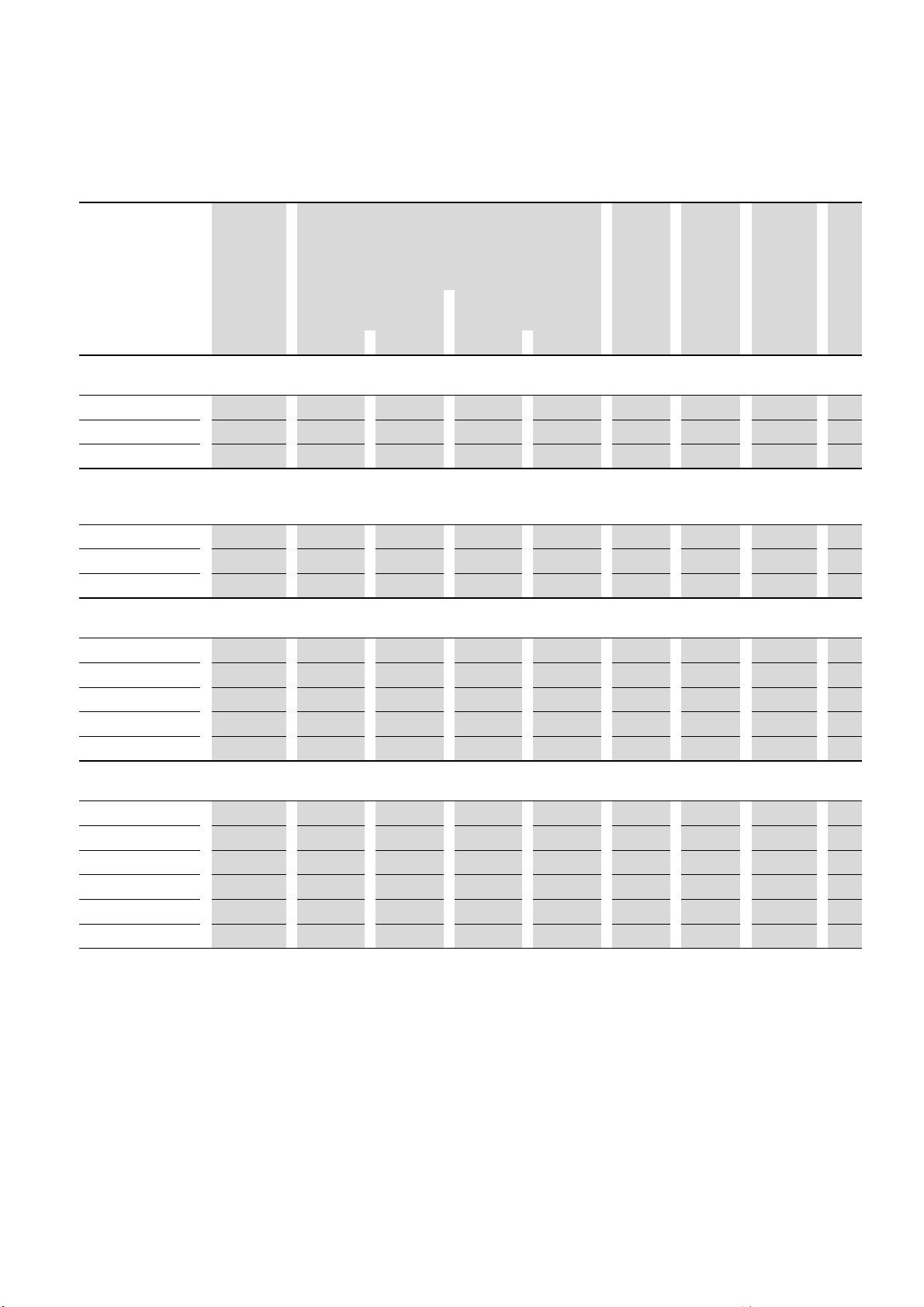
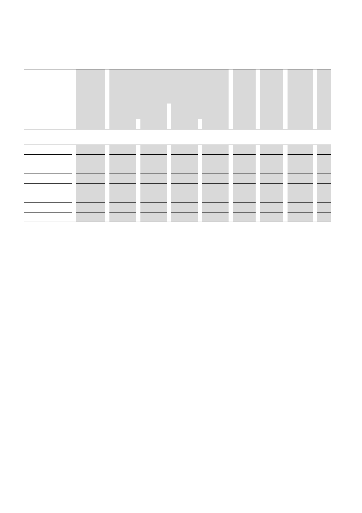
1.4.4 Features
1 DC1 device series
1.4 Rated data
Part no.
Rated current
I
e
[A] [kW] [A]
Assigned motor power
P
(230 V, 50 Hz)
1)
P
(220 - 240 V, 60 Hz)
[HP] [A]
EMV filter
(integrated)
N = No
F = Yes
1)
Brake
chopper
N = No
B = Yes
(integrated)
Degree of
IP FS
protection
Mains supply voltage: 1 AC 230 V
Motor connection voltage: 1 AC 230 V, 50/60 Hz (AC motor)
DC1-S24D3…
4.3 0.37 3 1/2 4.9 N, F N IP20, IP66 FS1
DC1-S27D0… 7 0.75 5 1 8 N, F N IP20, IP66 FS1
DC1-S2011… 11 1.1 7.5 1-1/2 10 N, F N, B IP20, IP66 FS2
Mains supply voltage: 1 AC 115 V, 50/60 Hz (voltage doubler), EMC: no internal radio interference suppression filter
Note: The
115 V mains supply voltage is increased to 230 V (output voltage) by an internal voltage doubler.
Motor connection voltage: 3 AC 230 V, 50/60 Hz
DC1-1D2D3N…
2.3 0.37 2 1/2 2.2 N N IP20, IP66 FS1
DC1-1D4D3N… 4.3 0.75 3.2 1 4.2 N N IP20, IP66 FS1
DC1-1D5D8N… 5.8 1.1 4.6 1-1/2
2)
2)
6
N N, B IP20, IP66 FS2
Mains supply voltage: 1 AC 230 V, 50/60 Hz
Motor connection voltage: 3 AC 230 V, 50/60 Hz
DC1-122D3…
2.3 0.37 2 1/2 2.2 N, F N IP20, IP66 FS1
DC1-124D3… 4.3 0.75 3.2 1 4.2 N, F N IP20, IP66 FS1
DC1-127D0xN… 7 1.5 6.3 2 6.8 N, F N IP20, IP66 FS1
DC1-127D0xB…
7 1.5 6.3 2 6.8 N, F B IP20, IP66 FS2
DC1-12011… 10.5 2.2 8.7 3 9.6 N, F N, B IP20, IP66 FS2
Mains supply voltage: 3 AC 230 V, 50/60 Hz
Motor connection voltage: 3 AC 230 V, 50/60 Hz
DC1-322D3…
DC1-324D3…
DC1-327D0xN…
DC1-327D0xB…
2.3 0.37 2 1/2 2.2 N, F N IP20, IP66 FS1
4.3 0.75 3.2 1 4.2 N, F N IP20, IP66 FS1
7 1.5 6.3 2 6.8 N, F N IP20, IP66 FS1
7 1.5 6.3 2 6.8 N, F B IP20, IP66 FS2
DC1-32011… 10.5 2.2 8.7 3 9.6 N, F N, B IP20, IP66 FS2
DC1-32018… 18 4 14.8 5 15.2 N, F N, B IP20, IP66 FS3
1) The rated motor currents apply to normal internally and surface-cooled three-phase asynchronous motor
(1500 rpm at 50 Hz, 1800 rpm
at 60 Hz).
2) Take motor data into account (6 A = normalized rated value as per UL 580 C)
Operation may be limited to a reduced motor load.
Size
DC1 frequency inverter 10/12 MN04020003Z-EN www.eaton.com 19
1 DC1 device series
1.4 Rated data
Part no.
Rated current
I
e
[A] [kW] [A]
Assigned motor power
P
(400 V, 50 Hz)
1)
P
(440 - 480 V, 60 Hz)
[HP] [A]
EMC filter
(integrated)
N = No
F = Yes
1)
Brake
chopper
N = No
B = Yes
(integrated)
Degree of
IP FS
protection
Mains supply voltage: 3 AC 400 V, 50 Hz / 480 V, 60 Hz
Motor connection voltage: 3 AC 400 V, 50 Hz / 440 - 480 V, 60 Hz
DC1-342D2…
2.2 0.75 1.9 1 2.1 N, F N IP20, IP66 FS1
DC1-344D1xN… 4.1 1.5 3.6 2 3.4 N, F N IP20, IP66 FS1
DC1-344D1xB… 4.1 1.5 3.6 2 3.4 N, F B IP20, IP66 FS2
DC1-345D8…
DC1-349D5…
5.8 2.2 5 3 4.8 N, F N, B IP20, IP66 FS2
9.5 4 8.5 5 7.6 N, F N, B IP20, IP66 FS2
DC1-34014… 14 5.5 11.3 7-1/2 11 N, F N, B IP20, IP66 FS3
DC1-34018… 18 7.5 15.2 10 14 N, F N, B IP20, IP66 FS3
DC1-34024…
1) The rated motor currents apply to normal internally and surface-cooled three-phase asynchronous motor
(1500 rpm at 50 Hz, 1800 rpm
24 11 21.7 15 21 N, F N, B IP20, IP66 FS3
at 60 Hz).
Size
20 DC1 frequency inverter 10/12 MN04020003Z-EN www.eaton.com
1.5 DC1 layout
⏚
L1/L
L2/N
L3
⏚
U
V
W
1
2
3
4
5
6
7
8
9
10
11
⑧
⑦
⑥
⑤
①
②
③
④
1 DC1 device series
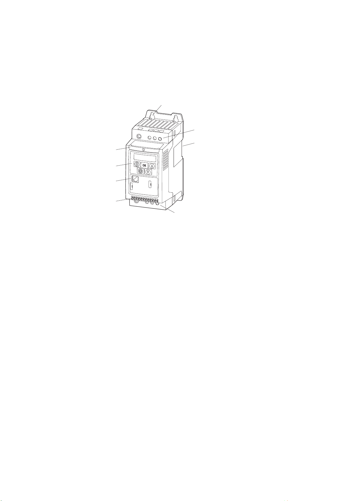
1.5 DC1 layout
The following drawing shows examples of named elements of the DC1 frequency inverters in different frame sizes.
Figure 5: DC1 frequency inverter layout,
sizes FS1, FS2, and FS3
a Fixing holes (screw fastening)
b Connection terminals in power section (mains side)
c Cutout for mounting on mounting rail
d Connection terminals in power section (motor feeder)
e Control terminals (plug-in)
f Communication interface (RJ45)
g Operating unit with 5 control buttons and LED display
h Info card
DC1 frequency inverter 10/12 MN04020003Z-EN www.eaton.com 21
1 DC1 device series
+
-
+
-
+
-
M
3 ~
U
L3
L2/N
L1/L
W
V
U
②①③④⑤⑥⑦
⑩
⑧⑨
DC-
DC+ BR
EMC VAR
CPU
1 … 11
PES
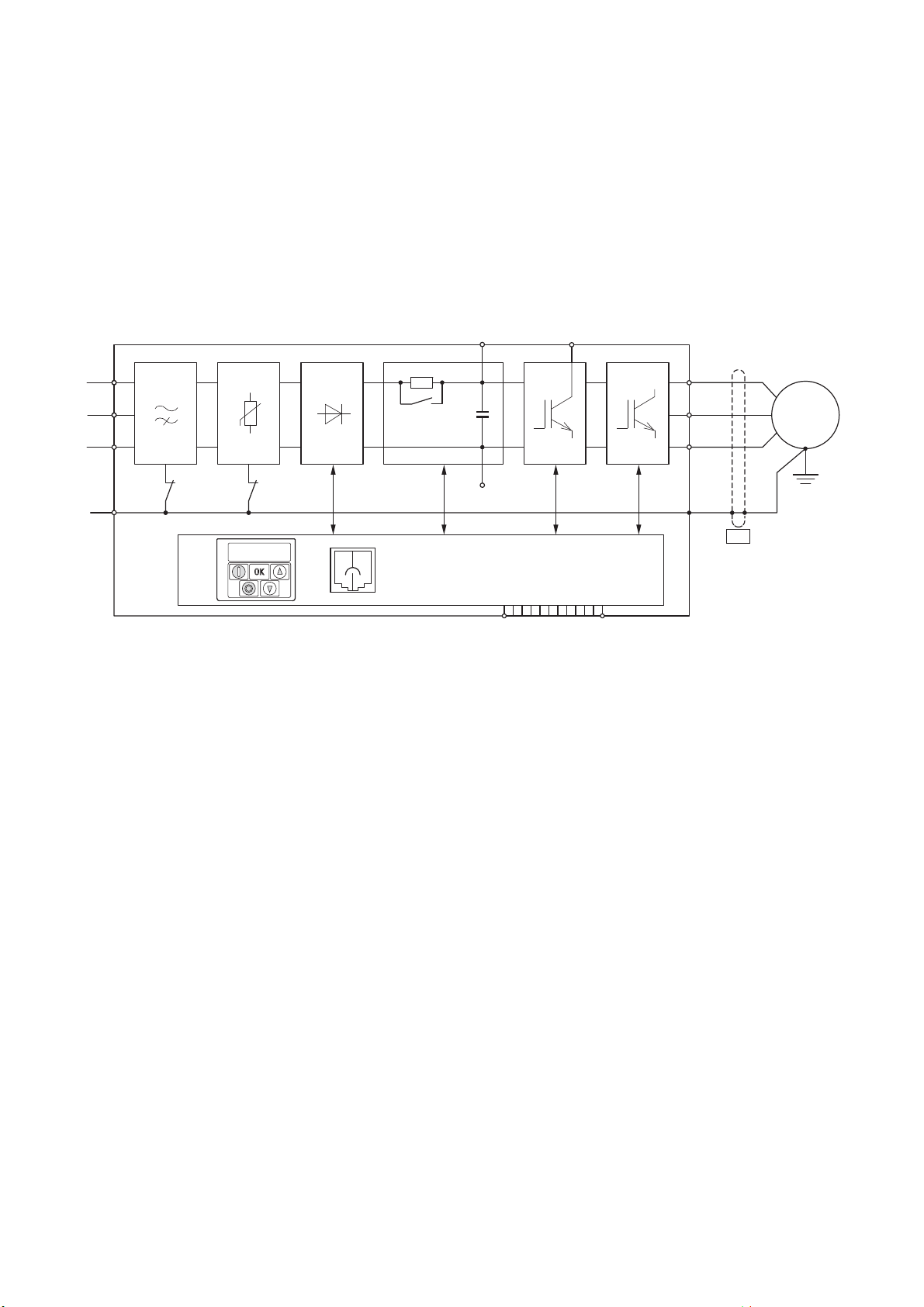
1.6 Features
1.6 Features
DC1 series frequency inverters convert the voltage and frequency of an
existing AC supply system into a DC voltage.
This DC voltage is then used to generate a single-phase or three-phase AC
voltage with an adjustable frequency and assigned amplitude values for the
variable speed control of AC motors and three-phase asynchronous motors.
Figure 6: Block diagram; components in a DC1 frequency inverter
a L1/L, L2/N, L3, PE supply; mains supply voltage U
DC1-S2… (1 AC 230 V) for AC motors
DC1-1D…: single-phase mains connection (1 AC 115 V), with voltage doubler
DC1-12…: single-phase mains connection (1 AC/2 AC 230 V/240 V), motor feeder (3 AC 230 V)
DC1-32…: three-phase mains connection (3 AC 230 V/240 V), motor feeder (3 AC 230 V)
DC1-34…: three-phase mains connection (3 AC 400 V/480 V), motor feeder (3 AC 400 V)
b Internal radio interference suppression filter (not in DC1-1D…), EMC connection to PE
c Internal voltage filter, VAR connection to PE
d Rectifier bridge: it converts the AC voltage of the electrical supply to a DC voltage.
e DC link with charging resistor, capacitor and switched-mode power supply unit (SMPS = Switching-
Mode Power Supply).
f Brake chopper for external braking resistor (DC+ and BR connection only in FS2 and FS3 sizes)
g Inverter. The IGBT based inverter converts the DC voltage of the DC link (U
with variable amplitude and frequency (f2).
LN=Ue
at 50/60 Hz:
) into the AC voltage (U2)
DC
22 DC1 frequency inverter 10/12 MN04020003Z-EN www.eaton.com

1 DC1 device series
1.6 Features
h Motor connection with output voltage U2 (0 to 100 % Ue) and output frequency f2 (0 to 500 Hz)
The connection in the motor feeder is implemented with a screened cable that is earthed on
both sides across a large area (PES).
Rated operational current (I
DC1-S2…: 4.3 - 11 A
DC1-1D…: 2.3 - 5.8 A
DC1-12…: 2.3 - 10.5 A
DC1-32…: 2.3 - 18 A
DC1-34…: 2.2 - 24 A
100% at an ambient temperature of +50 °C with an overload capability of 150 % for 60 s
and a starting current of 175% for 2 s.
i Three-phase asynchronous motor
Variable speed control of motors for assigned motor shaft powers (P
DC1-1D…: 0.37 - 1.1 kW (230 V, 50 Hz) or 0.5 - 1 HP (230 V, 60 Hz)
DC1-12…: 0.37 - 2.2 kW (230 V, 50 Hz) or 0.5 - 3 HP (230 V, 60 Hz)
DC1-32…: 0.37 - 4 kW (230 V, 50 Hz) or 0.5 - 5 HP (230 V, 60 Hz)
DC1-34…: 0.75 - 11 kW (400 V, 50 Hz) or 1 - 15 HP (460 V, 60 Hz)
AC motor for assigned motor shaft powers (P
DC1-S2…: 0.37 - 1.1 kW (230 V, 50 Hz) or 0.5 - 1.5 HP (230 V, 60 Hz)
j Control section with operating unit and control buttons, 7-digital display assembly, control voltage,
plug-in control signal terminals, relays, and RJ-45 port for computer and fieldbus connection
, output current):
e
):
2
):
2
DC1 frequency inverter 10/12 MN04020003Z-EN www.eaton.com 23
1 DC1 device series
1.7 Selection criteria
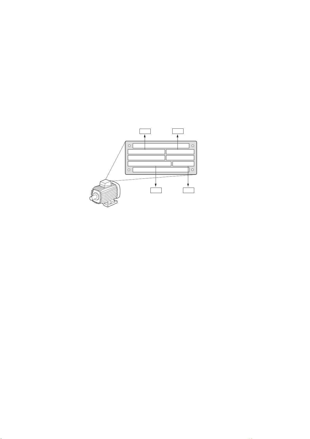
1.7 Selection criteria
Select the frequency inverter according to the supply voltage ULN of the supply system and the rated operational current of the assigned motor. The circuit type ( / ) of the motor must be selected according to the rated operational current.
The rated output current I
of the frequency inverter must be greater than or
e
equal to the rated motor current.
cos ϕ 0.79
-1
P-08
50 Hz
P-09
P-07
230/400 V 3.2/1.9 A
0.75 kW
1410 min
P-10
Figure 7: Selection criteria
When selecting the drive, the following criteria must be known:
• Type of motor (three-phase asynchronous motor)
• Mains voltage = rated operating voltage of the motor (e. g. 3~ 400 V),
• Rated motor current (recommended value, dependent on the circuit type
and the power supply)
• Load torque (quadratic, constant),
• Starting torque,
• Ambient air temperature (rated value e. g. +40 °C).
→
frequency inverter, the motor currents are
separated by effective and idle current components.
When you select a frequency inverter, make sure that it can
supply the total resulting current. If necessary, for dampening
and compensating the deviating current values, motor reactors
or sinusoidal filters must be installed between the frequency
inverter and the motor.
24 DC1 frequency inverter 10/12 MN04020003Z-EN www.eaton.com
When connecting multiple motors in parallel to the output of a
added geometrically –

1.8 Proper use
1 DC1 device series
1.8 Proper use
The DC1 frequency inverters are not domestic appliances. They are designed
only for industrial use as system components.
The DC1 frequency inverters are electrical devices for controlling variable
speed drives with three-phase motors. They are designed for installation in
machines or for use in combination with other components within a machine
or system
After installation in a machine, the frequency inverters must not be taken into
operation until the associated machine has been confirmed to comply with
the safety requirements of Machinery Safety Directive (MSD) 89/392/EEC
(meets the requirements of EN 60204). The user of the equipment is responsible for ensuring that the machine use complies with the relevant EU Directives.
The CE markings on the DC1 frequency inverter confirm that, when used in a
typical drive configuration, the apparatus complies with the European Low
Voltage Directive (LVD) and the EMC Directives (Directive 73/23/EEC, as
amended by 93/68/EEC and Directive 89/336/EEC, as amended by 93/68/
EEC).
In the described system configurations, DC1 frequency inverters are suitable
for use in public and non-public networks.
A connection of a DC1 frequency inverter to IT networks (networks without
reference to earth potential) is permissible only to a limited extent, since the
device’s built-in filter capacitors connect the network with the earth potential
(enclosure).
On earth free networks, this can lead to dangerous situations or damage to
the device (isolation monitoring required).
→
To the output (terminals U, V, W) of the DC1 frequency inverter
you must not:
• connect a voltage or capacitive loads (e.g. phase compensa-
tion capacitors),
• connect multiple frequency inverters in parallel,
• make a direct connection to the input (bypass).
Observe the technical data and connection requirements.
For additional information, refer to the equipment nameplate or label of the
frequency inverter and the documentation. Any other usage constitutes
improper use.
DC1 frequency inverter 10/12 MN04020003Z-EN www.eaton.com 25

1 DC1 device series
1.9 Maintenance and inspection
1.9 Maintenance and inspection
DC1 series frequency inverters will be maintenance-free as long as the general rated operational data ( Section 1.4.3, „General rated operational
data“, page16) is adhered to and the specific technical data (see appendix)
for the corresponding ratings is taken into account. Please note, however,
that external influences may affect the operation and lifespan of a DC1 frequency inverter.
We therefore recommend that the devices are checked regularly and the
following maintenance measures are carried out at the specified intervals.
Table 2: Recommended maintenance for DC1 frequency inverters
Maintenance measures Maintenance interval
Clean cooling vents (cooling slits) Please enquire
Check the fan function 6 - 24 months (depending on the environment)
Check the filter in the control panel doors
(see the manufacturer's specifications)
Check all earth connections to make sure they
are intact
Check the tightening torques of the terminals
(control signal terminals, power terminals)
Check connection terminals and all metallic
surfaces for corrosion
Motor cables and shield connection (EMC)
Charge capacitors
6 - 24 months (depending on the environment)
On a regular basis, at periodic intervals
On a regular basis, at periodic intervals
6 - 24 months; when stored, no more than 12 months later
(depending on the environment)
According to manufacturer specifications, no later than 5 years
12 months
(→ Section 1.11, „Charging the internal DC link capacitors“)
1.10 Storage
There are no plans for replacing or repairing individual components of DC1
frequency inverters.
If the DC1 frequency inverter is damaged by external influences, repair is not
possible.
Dispose of the device according to the applicable environmental laws and
provisions for the disposal of electrical or electronic devices.
If the DC1 frequency inverter is stored before use, suitable ambient conditions must be ensured at the site of storage:
• Storage temperature: -40 - +70 °C,
• Relative average air humidity: < 95 %, non condensing (EN 50178),
• To prevent damage to the RASP DC link capacitors, storage times longer
than 12 months are not recommended
( Section 1.11, „Charging the internal DC link capacitors“).
26 DC1 frequency inverter 10/12 MN04020003Z-EN www.eaton.com
 Loading...