

Eaton DB3B Technical Manual
Technical manual
Sounder - DB3B

DISCLAIMER OF WARRANTIES AND LIMITATION OF LIABILITY
DISCLAIMER OF WARRANTIES AND LIMITATION OF LIABILITY
The information, recommendations, descriptions and safety notations in this document are based on Eaton Corporation’s
(“Eaton”) experience and judgment and may not cover all contingencies. If further information is required, an Eaton sales
office should be consulted. Sale of the product shown in this literature is subject to the terms and conditions outlined in
appropriate Eaton selling policies or other contractual agreement between Eaton and the purchaser.
THERE ARE NO UNDERSTANDINGS, AGREEMENTS, WARRANTIES, EXPRESSED OR IMPLIED, INCLUDING
WARRANTIES OF FITNESS FOR A PARTICULAR PURPOSE OR MERCHANTABILITY, OTHER THAN THOSE
SPECIFICALLY SET OUT IN ANY EXISTING CONTRACT BETWEEN THE PARTIES. ANY SUCH CONTRACT STATES THE
ENTIRE OBLIGATION OF EATON. THE CONTENTS OF THIS DOCUMENT SHALL NOT BECOME PART OF OR MODIFY
ANY CONTRACT BETWEEN THE PARTIES.
In no event will Eaton be responsible to the purchaser or user in contract, in tort (including negligence), strict liability or
other-wise for any special, indirect, incidental or consequential damage or loss whatsoever, including but not limited to
damage or loss of use of equipment, plant or power system, cost of capital, loss of power, additional expenses in the
use of existing power facilities, or claims against the purchaser or user by its customers resulting from the use of the
information, recommendations and descriptions contained herein. The information contained in this manual is subject to
change without notice.
ii SOUNDER - DB3B TM264 June 2019 www.eaton.com

Sounder - DB3B
English
Contents
1.0 INTRODUCTION . . . . . . . . . . . . . . . . . . . . . . . . . . . . . . . . . . . . . . . . . . . . . . . . . . . . . . . . . . . . . . . . . . . . . .1
2.0 GENERAL SAFETY MESSAGES AND WARNINGS . . . . . . . . . . . . . . . . . . . . . . . . . . . . . . . . . . . . . . . . . .1
3.0 INSTALLATION .......................................................................1
Access to terminals .......................................................................... 1
Wiring details. . . . . . . . . . . . . . . . . . . . . . . . . . . . . . . . . . . . . . . . . . . . . . . . . . . . . . . . . . . . . . . . . . . . . . . . . . . . . . . 2
Ex d – AC input wiring details (Types 1 & 2) ....................................................... 2
Ex de – AC input wiring details (Types 3 & 4) ...................................................... 2
Ex d & Ex de – DC input, 3 stage without monitoring wiring details (Types 5 & 6) ......................... 3
Ex d & Ex de – DC Input, 3 stage without monitoring wiring details (Types 5 & 6) ......................... 3
Ex d & Ex de – DC input, dual stage common +ve with monitoring (standard configuration) wiring details
(Types 7 & 8) .............................................................................. 4
Ex d & Ex de – DC input, up to 3 stage with or without monitoring (alternative configuration) wiring details
(Types 9 & 10) ............................................................................. 4
Ex d – DC input with voltage free stage activation wiring details (Type 11) ............................... 5
Ex de – DC input with voltage free stage activation wiring details (Type 12) .............................. 5
4.0 OPERATION .........................................................................5
5.0 MAINTENANCE ......................................................................7
6.0 CERTIFICATION/APPROVALS ...........................................................8
lECEx units ................................................................................ 8
Gas & Dust (GD) certified units ................................................................. 8
ATEX units ................................................................................. 8
Gas (G) certified units ........................................................................ 8
Gas & dust (GD) certified units ................................................................. 8
These units also have the following approvals: ..................................................... 8
7.0 SPECIAL CONDITIONS FOR SAFE USE ...................................................9
8.0 FUNCTIONAL SAFETY ...............................................................10
Introduction ..................................................................................... 10
Assessment of functional safety ............................................................... 10
Conditions of safe use ........................................................................11
SOUNDER - DB3B TM264 June 2019 www.eaton.com
iii

Sounder - DB3B
English
iv
SOUNDER - DB3B TM264 June 2019 www.eaton.com

Sounder - DB3B
English
1.0 Introduction
This range of sounders, intended for use in potentially
explosive gas and dust atmospheres, is available in
versions suitable for use in the following gas/dust groups:
The range is available in versions suitable for use in either
gas (G) or gas and dust (GD) groups.
ote:N (G) unit has nominally 6dB higher output than
(GD) unit.
The Ex enclosure is manufactured from a UV stable
glass reinforced polyester with a rugged thermoplastic
flare. Stainless steel mounting bracket, cover screws and
fixings are incorporated throughout thus ensuring a corrosion free product.
An optional Ex e terminal chamber is available (see certification section for further details).
An uncertified version is available for use in
non-explosive atmospheres.
2.0 General safety messages and
warnings
All instructions and safety messages in this manual must
be followed to allow safe installation of the device. The
device must only be installed and maintained by correctly
trained site personnel/installers.
I. To reduce the risk of ignition of hazardous
atmospheres and shock, do not apply power to
the device until installation has been completed
and the device is fully sealed and secured.
II. To reduce the risk of ignition of hazardous
atmospheres and shock, keep device tightly
closed when the circuit is energised.
III. Before removing the cover for installation or
maintenance, ensure that the power to the device
is isolated.
IV. Following installation, test the device to ensure
correct operation.
V. Following installation ensure a copy
of this manual is made available to all
operating personnel.
VI. When installing the device, requirements for
selection, installation and operation should be
referred to e.g. IEE Wiring Regulations and the
‘National Electrical Code’ in North America.
Additional national and/or local requirements
may also apply.
VII. Cable termination should be in accordance with
the specification applying to the required application. MEDC recommends that all cables and
cores should be correctly identified. Please refer
to the wiring diagram in this manual (or separate
diagram provided with the unit).
VIII. Ensure that only the correct listed or certified
cable glands are used and that the assembly is
shrouded and correctly earthed.
IX. Ensure that only the correct listed or certified
stopping plugs are used to blank off unused
gland entry points and that the NEMA/IP rating of
the unit is maintained.
X. MEDC recommend the use of a sealing
compound such as HYLOMAR PL32 on the
threads of all glands and stopping plugs and/or a
suitable sealing washer in order to maintain the
IP rating of the unit.
XI. On Exde units, a suitable sealing washer must be
fitted to all glands and stopping plugs fitted into
the Exe enclosure.
XII. The end user or installer shall ensure that this
equipment is protected against external influences which could adversely affect the explosion
protection, or contact the manufacturer if in doubt
of the suitability of this equipment in the environment in which it is to be installed.
XIII. Ex d Units
The internal earth terminal must be used for
protective earthing when required. Do not remove
the internal ground strap from the earth terminal
where fitted.
For units with metric entries; gland continuity
and earthing may be achieved with an optional
external earth plate. If the external plate is fitted,
a thread sealing compound such as HYLOMAR
PL32 must beemployed to maintain the IP rating
of the unit.
Ex de Units
The internal/external earth stud must be used
for equipment grounding when required. Gland
continuity is achieved if the optional internal earth
plate is fitted.
XIV. When installing the device, MEDC recommends
the use of stainless steel fasteners. Ensure that all
nuts, bolts and fixings are secure.
XV. The unit should be positioned such that debris,
dust or water cannot settle in the re-entrant horn.
XVI. The unit should be positioned such that any solid
object, not part of the equipment, is a minimum
of 40mm from the Ex d flamepath joint.
XVII. The purchaser should make the
manufacturer aware of any external effects or
aggressive substances that the equipment may
be exposed to
3.0 Installation
The unit is mounted via 2 off Ø9mm fixing holes in the
U-shaped stirrup/mounting bracket. If required, the unit
can be initially placed via the Ø13mm central hole in the
stirrup. The unit can then be rotated to the required position and fixed via the other holes.
If ordered with the unit, a swivel mounting bracket option
is available to allow further rotational adjustment to
the unit.
The fixing holes have been designed to accept an M8
screw or bolt.
Access to terminals
On Ex d versions, the cover is secured with 6 off M5
cover screws (4.0mm A/F hexagon key). Once the cover
fixings are unscrewed, the cover can be lifted away from
the enclosure to gain access to the interior. The cover
fixings are captive and will remain in the cover.
1SOUNDER - DB3B TM264 June 2019 www.eaton.com
Sounder - DB3B
English
On Ex de versions the removable cover is secured using
3 off M5 cover screws (4.0mm A/F hexagon key). Once
the cover fixings are unscrewed, the cover can be lifted
away from the enclosure to gain access to the interior.
The cover fixings are captive and will remain in the cover.
All terminal screws, used and unused, shall be tightened
down. Once termination is complete, carefully replace
the cover assembly back onto the body, avoiding damage
to the mating surfaces. Tighten the cover screws evenly.
On Ex-de certified versions, ensure the maximum torque
value for the cover screws is observed, as marked on
the Ex e cover. Ensure the O-ring is seated correctly on
the cover during re-assembly. On Ex d certified versions,
ensure the required maximum gap of 0.04mm is maintained between the cover and the base once assembled.
Wiring details
The unit is available in a number of basic configurations:
1. Ex d - AC input, single stage.
2. Ex d - AC input, dual stage with voltage-free
stage selection.
3. Ex de - AC input, single stage.
4. Ex de - AC input, dual stage with voltage-free
stage selection.
5. Ex d - DC input, up to 3 user selectable stages
without monitoring.
6. Ex de - DC input, up to 3 user selectable stages
without monitoring.
7. Ex d - DC input, up to 2 user selectable stages with
EOL/monitoring (standard configuration).
8. Ex de - DC input, up to 2 user selectable stages with
EOL/monitoring (standard configuration).
9. Ex d - DC input, up to 3 user selectable stages with
optional EOL/monitoring (alternative configuration).
10. Ex de - DC input, up to 3 user selectable stages with
optional EOL/monitoring (alternative configuration).
11. Ex d - DC input, 5 user selectable stages with voltage
free stage selection with or without monitoring.
12. Ex de - DC input, 5 user selectable stages
with voltage free stage selection with or
without monitoring.
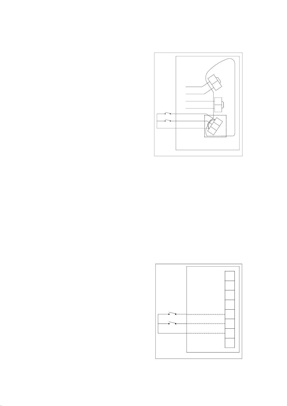
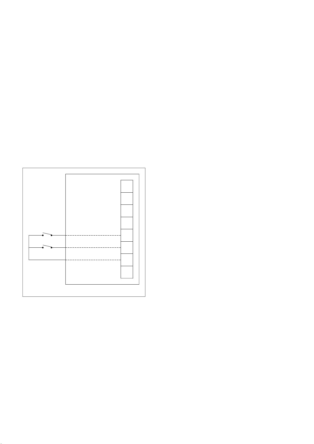
Ex d – AC input wiring details (Types 1 & 2)
•
Type 1: Connect the live and neutral supply wires to
the terminals as detailed in the wiring diagram. The unit
will be supplied with the link between R1 and R0 fitted
to the terminals. When power is applied to the unit,
the stage 1 tone will be produced as selected on the
5- way DIP switch.
•
Type 2: Connect the live and Neutral supply wires to
the terminals as detailed in the wiring diagram. The unit
will be supplied with no link fitted between R1 and R0.
Connect wires and remote switches to terminals R0,
R1 and R2 as shown. When power is initially applied
to the unit, no tone will be produced. When the switch
connected to R1 is closed, the stage 1 tone will be
produced as selected by the 5-way DIP switch on the
electronics assembly. When the switch connected to R2
is closed, the pre-selected tone for stage 2 is produced.
See tone table 2 for details of pre-selected tones.
ote:N Closing both switches will produce no tone.
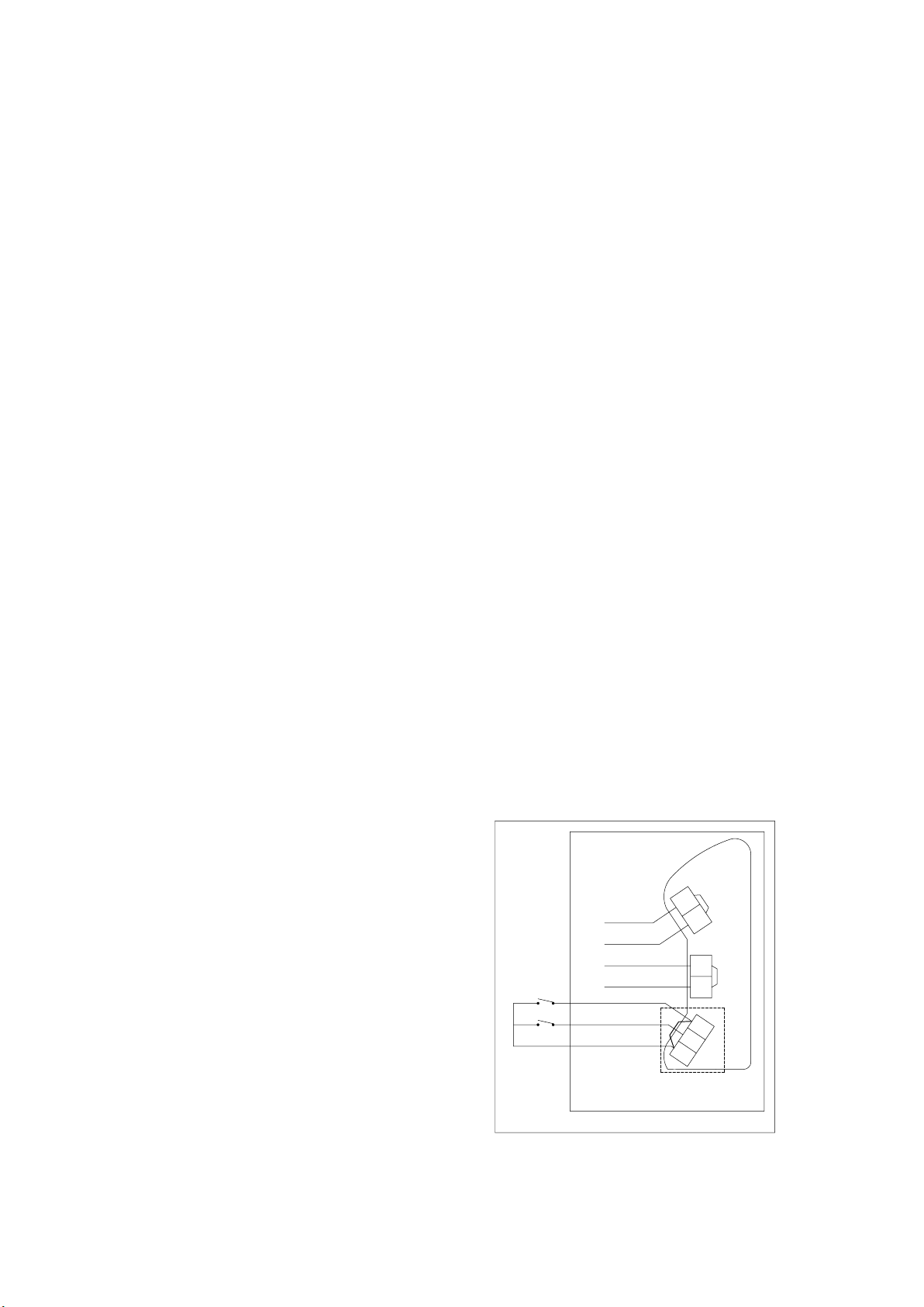
Ex d – AC input wiring diagram (Types 1 & 2)
NEUTRAL IN
NEUTRAL OUT
CUSTOMER
WIRING
LIVE IN
LIVE OUT
STAGE 1
STAGE 2
COMMON
DB3B Ex d CHAMBER
ELECTRONICS
L
L
R1
R2
R0
VOLTAGE-FREE
STAGE
ACTIVATION
TERMINALS
ASSEMBLY
N
N
Ex de – AC input wiring details (Types 3 & 4)
•
Type 3: Connect the live and neutral supply wires to
the terminals as detailed in the wiring diagram. When
power is applied to the unit, the stage 1 tone will be
produced as selected on the 5- way DIP switch inside
the Ex d chamber.
•
Type 4: Connect the live and Neutral supply wires
to the terminals as detailed in the wiring diagram.
When power is initially applied to the unit, no tone
will be produced. Connect wires and remote switches
to terminals R0, R1 and R2 as shown. When the
switch connected to R1 is closed, the stage 1 tone
will be produced as selected by the 5-way DIP
switch on the electronics assembly. When the switch
connected to R2 is closed, the pre-selected tone for
stage 2 is produced. See tone table 2 for details of
pre-selected tones
ote:N Closing both switches will produce no tone.
Ex de – AC input wiring diagram (Types 3 & 4)
1
2
3
4
1
2
3
4
CUSTOMER
WIRING
LIVE IN
LIVE OUT
NEUTRAL IN
NEUTRAL OUT
STAGE 1 (R1)
STAGE 2 (R2)
COMMON (R0)
DB3B Ex e CHAMBER
2 SOUNDER - DB3B TM264 June 2019 www.eaton.com
Sounder - DB3B
English
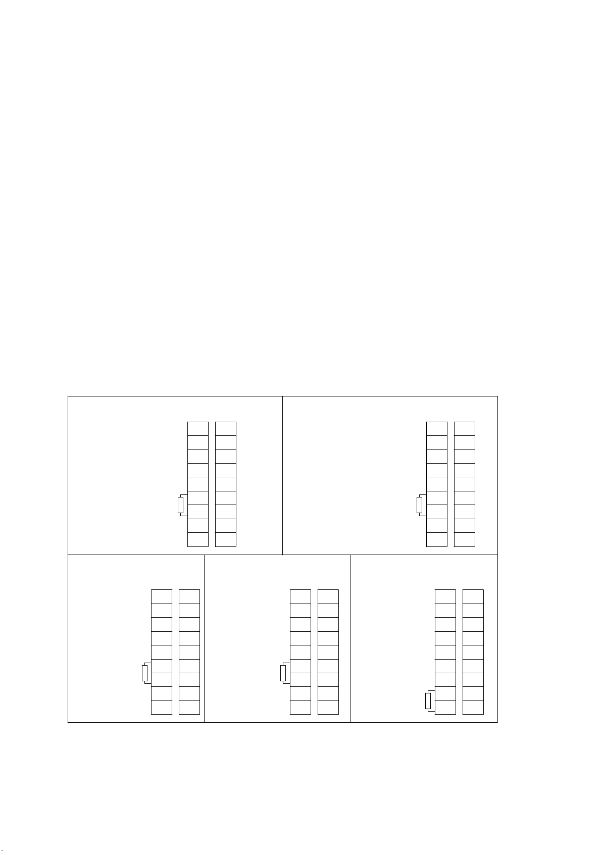
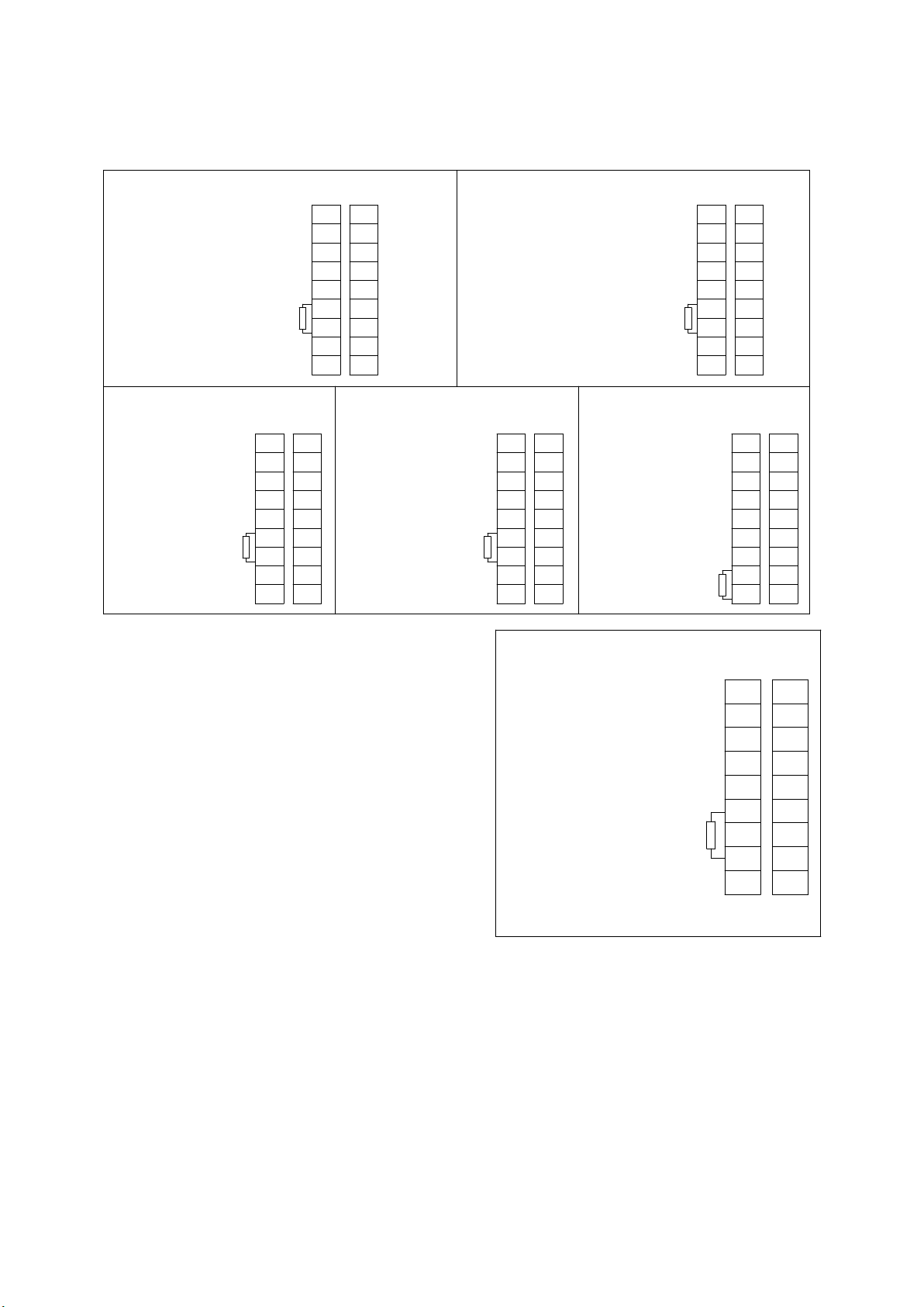
Ex d & Ex de – DC input, 3 stage without
monitoring wiring details (Types 5 & 6)
This type can be configured in a number of different ways
depending on requirements. Independent tone selection
for all 3 stages is via the 3 off 5-way DIP switches fitted
to the electronics assembly:
•
2-wire system (Single stage): Connect the positive
and negative supply wires to the terminals as detailed
in the wiring diagram.
•
2-wire system (Dual stage, reverse polarity): Connect
the positive and negative supply wires to the terminals
as detailed in the wiring diagram. The second stage
is produced by reversing the polarity of the supply to
theunit.
•
3-wire system (Dual stage, common +ve): Connect 3
supply wires to the terminals as detailed in the wiring
diagram (1 common +ve wire and 2 -ve wires). Stage 1
is produced when power is applied across the common
+ve and stage 1 -ve terminals. Stage 2 is produced
when power is applied across the common +ve and
stage 2 -ve terminals.
•
3-wire system (Dual stage, common -ve): Connect
3supply wires to the terminals as detailed in the wiring
diagram (2 +ve wires and 1 common -ve wire). Stage
1 is produced when power is applied across the stage
1 +ve and common -ve terminals. Stage 2 is produced
when power is applied across the stage 2 +ve and
stage common -ve terminals.
•
4-wire system (Triple stage, Common -ve): Connect
4 supply wires to the terminals as detailed in the wiring
diagram (3 +ve wires and 1 common -ve wire). Stage
1 is produced when power is applied across the stage
1 +ve and common -ve terminals. Stage 2 is produced
when power is applied across the stage 2 +ve and
common -ve terminals. Stage 3 is produced when
power is applied across the stage 3 +ve and common
-ve terminals.
All versions are supplied with terminals to allow loop-in
loop-out connection of the supply wires.
ote:N If an EOL resistor is specified on a DC unit, it will
be fitted as standard across terminals 5 & 6 in the
Ex d chamber (see below). Re-position EOL as
required for other configurations.
When positioning the EOL, ensure there is a minimum of
14mm free space between the resistor body and terminal
block and ensure the resistor is not in contact with the
PCB or housing.
Ex d & Ex de – DC Input, 3 stage without monitoring wiring details (Types 5 & 6)
DB3B DC SINGLE STAGE
STAGE 1 +VE IN
STAGE 1 -VE IN
STAGE 1 +VE OUT
STAGE 1 -VE OUT
DB3B DC DUAL STAGE
COMMON POSITIVE
CONFIGURATION
COMMON +VE IN
STAGE 1 -VE IN
NOT USED
STAGE 2 -VE IN
COMMON +VE OUT
STAGE 1 -VE OUT
NOT USED
STAGE 2 -VE OUT
CONFIGURATION
NOT USED
NOT USED
NOT USED
NOT USED
R1
Ex d
Ex de
1
1
2
2
3
3
4
4
5
R1
1
6
2
7
3
8
4
Ex d
Ex de
1
1
2
2
3
3
4
4
5
1
6
2
7
3
8
4
STAGE 1 +VE IN
COMMON -VE IN
STAGE 2 +VE IN
STAGE 1+VE OUT
COMMON -VE OUT
STAGE 2 +VE OUT
STAGE 1 +VE IN/STAGE 2 -VE IN
STAGE 1 -VE IN/STAGE 2 +VE IN
STAGE 1 +VE OUT/STAGE 2 -VE OUT
STAGE 1 -VE OUT/STAGE 2 +VE OUT
DB3B DC DUAL STAGE
COMMON NEGATIVE
CONFIGURATION
Ex d
1
2
NOT USED
NOT USED
3
4
5
R1
6
7
8
DB3B DC DUAL STAGE
REVERSE POLARITY CONFIGURATION
Ex d
1
2
3
4
5
R1
6
7
8
Ex d
1
2
3
4
5
6
7
R1
8
Ex de
1
2
3
4
1
2
3
4
NOT USED
NOT USED
NOT USED
NOT USED
DB3B DC TRIPLE STAGE
COMMON NEGATIVE
CONFIGURATION
STAGE 2 +VE IN
STAGE 3 +VE IN
STAGE 1 +VE IN
COMMON -VE IN
STAGE 2 +VE OUT
STAGE 3 +VE OUT
STAGE 1 +VE OUT
COMMON -VE OUT
Ex de
1
2
3
4
1
2
3
4
Ex de
1
2
3
4
1
2
3
4
3SOUNDER - DB3B TM264 June 2019 www.eaton.com

Sounder - DB3B
R1
DB3B DC TRIPLE STAGE
COMMON POSITIVE
CONFIGURATION
DB3B DC DUAL STAGE
COMMON NEGATIVE CONFIGURATION
WITH MONITORING
MONITORING FUNCTIONALITY ONLY
AVAILABLE WHEN RESISTOR IS FITTED
R1
COMMON +VE IN
STAGE 1 -VE IN
STAGE 3 -VE IN
STAGE 2 -VE IN
COMMON +VE OUT
STAGE 1 -VE OUT
STAGE 3 -VE OUT
STAGE 2 -VE OUT
STAGE 2 +VE IN
M1 IN
STAGE 1 +VE IN
COMMON -VE / M2 IN
STAGE 2 +VE OUT
M1 OUT
STAGE 1 +VE OUT
COMMON -VE / M2 OUT
Ex d
1
2
3
4
5
6
7
8
Ex de
1
2
3
4
1
2
3
4
Ex d
1
2
3
4
5
6
7
8
Ex de
1
2
3
4
1
2
3
4
English
Ex d & Ex de – DC input, dual stage common
+ve with monitoring (standard configuration)
wiring details (Types 7 & 8)
Connect up to 4 supply wires to the terminals as detailed
in the wiring diagram. Stage 1 is produced when power is
applied across the common +ve and stage 1 -ve terminals.
Stage 2 is produced when power is applied across the
common +ve and stage 2 -ve terminals.
Monitoring functionality is obtained when the supply is
connected across M1 & M2 terminals.
ote:N monitored terminals are not polarity dependent.
Ex d & Ex de – DC input, dual stage common +ve
diagram (Types 7 & 8)
COMMON POSITIVE CONFIGURATION
COMMON +VE / M1 IN
COMMON +VE / M1 OUT
MONITORING FUNCTIONALITY ONLY
AVAILABLE WHEN RESISTOR IS FITTED
DB3B DC DUAL STAGE
WITH MONITORING
Ex d
M2 IN
M2 OUT
R1
STAGE 1 -VE IN
STAGE 2 -VE IN
STAGE 1 -VE OUT
STAGE 2 -VE OUT
Ex de
1
2
3
4
5
6
7
8
1
2
3
4
1
2
3
4
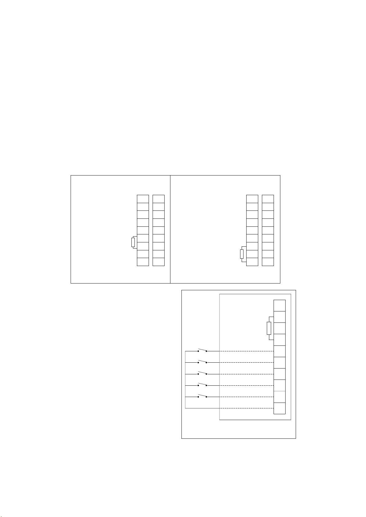
Ex d & Ex de – DC input, up to 3 stage with or
without monitoring (alternative configuration)
wiring details (Types 9 & 10
ote:N This alternative configuration must be specified
when ordering the unit.
This type can be connected either as a three stage
common –ve configuration, or if an optional EOL is specified
if can be configured as a dual stage common –ve system
with monitoring.
•
4-wire system (Triple stage, Common +ve): Connect
4 supply wires to the terminals as detailed in the wiring
diagram (1 common +ve wire and 3 -ve wires). Stage 1
is produced when power is applied across the common
+ve and stage 1 -ve terminals. Stage 2 is produced
when power is applied across the common +ve and
stage 2 -ve terminals. Stage 3 is produced when
power is applied across the common +ve and stage
3 -ve terminals.
•
4-wire system (Dual stage, common –ve with
monitoring): Connect up to 4 supply wires to the
terminals as detailed in the wiring diagram. Stage 1 is
produced when power is applied across the common
-ve and stage 1 +ve terminals. Stage 2 is produced
when power is applied across the common -ve and
stage 2 +ve terminals.
Monitoring functionality is obtained when the supply is
connected across M1 & M2 terminals.
Note: monitored terminals are not polarity dependent.
Ex d & Ex de – DC input, up to 3 stage diagrams
(Types 9 & 10)
)
4 SOUNDER - DB3B TM264 June 2019 www.eaton.com
Sounder - DB3B
English
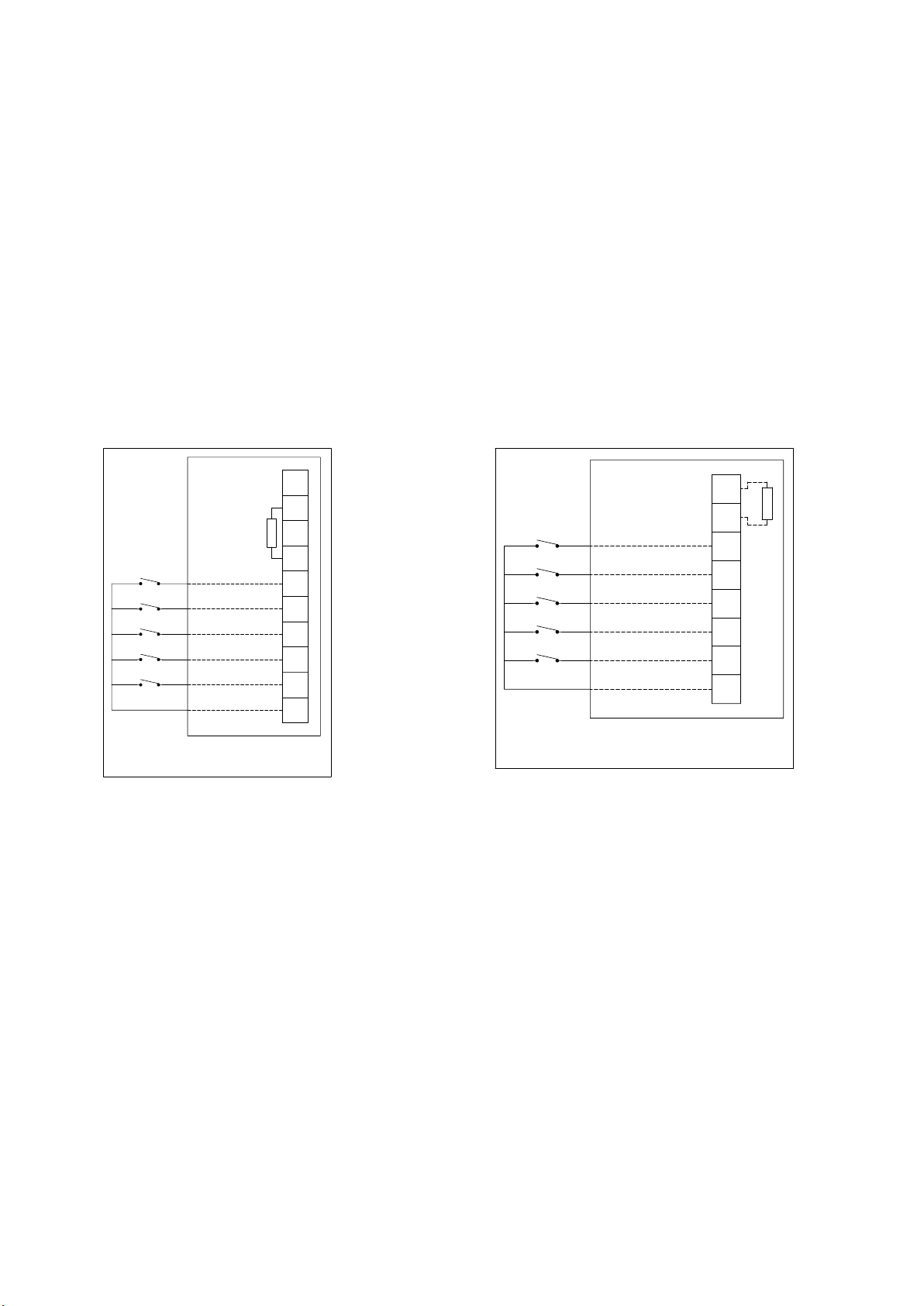
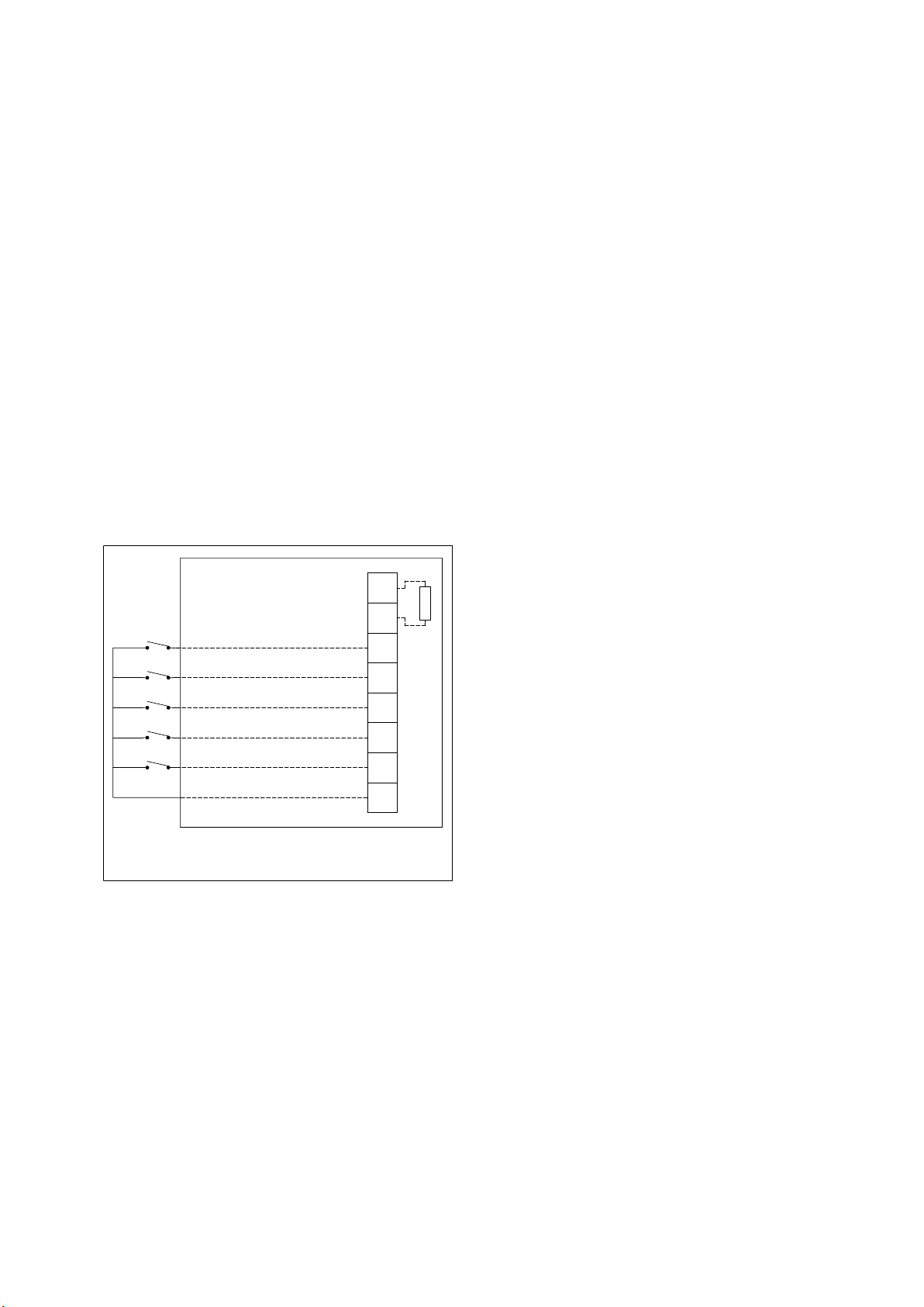
Ex d – DC input with voltage free stage
activation wiring details (Type 11)
Connect the positive (+ve) and negative (-ve) supply
wires to the terminals as detailed in the wiring diagram.
When power is applied to the unit, no tone will be
produced initially. Connect wires and remote switches to
terminals R0 to R5 as shown. When the switch connected
to R1 is closed, the stage 1 tone will be produced as
selected by the 5-way DIP switch on the electronics
assembly. When any of the other switches connected
to R2 to R5 is closed, the preselected tone for stages
2 to 5 are produced. See tone table 2 for details of
pre-selected tones.
ote:N Closing more than one switch at a time will result
in no tone being produced.
If a resistor (R1) is fitted, monitoring functionality is
obtained when the supply polarity is reversed.
COMMON
CUSTOMER
WIRING
R1 - OPTIONAL EOL RESISTOR
+VE IN
+VE OUT
-VE IN
-VE OUT
STAGE 1
STAGE 2
STAGE 3
STAGE 4
STAGE 5
DB3B Ex d CHAMBER
T1
T2
T3
R1
T4
R1
R2
R3
R4
R5
R0
Ex de – DC input with voltage free stage
activation wiring details (Type 12)
Connect the positive (+ve) and negative (-ve) supply
wires to the terminals as detailed in the wiring diagram.
When power is applied to the unit, no tone will be
produced initially. Connect wires and remote switches to
terminals R0 to R5 as shown. When the switch connected
to R1 is closed, the stage 1 tone will be produced as
selected by the 5-way DIP switch on the electronics
assembly. When any of the other switches connected
to R2 to R5 is closed, the pre-selected tone for stages
2 to 5 are produced. See tone table 2 for details of
pre-selected tones.
ote:N Closing more than one switch at a time will result
in no tone being produced.
If a resistor (R1) is fitted, monitoring functionality is
obtained when the supply polarity is reversed.
1
2
3
4
1
2
3
R1
4
CUSTOMER
WIRING
+VE IN/OUT
-VE IN/OUT
STAGE 1 (R1)
STAGE 2 (R2)
STAGE 3 (R3)
STAGE 4 (R4)
STAGE 5 (R5)
COMMON (R0)
DB3B Ex e CHAMBER
R1 - OPTIONAL EOL RESISTOR
LOCATED IN Ex d CHAMBER
4.0 Operation
The sounder is available in various AC input voltage
versions and a single DC input voltage version.
For AC versions, the nominal operating voltage is stated
on the unit label and the supply voltage tolerance is ±10%.
For DC versions, the absolute input voltage range is
11.0Vdc to 57.6Vdc.
If using an EOL resistor with a value between 700Ω and
2KΩ the maximum voltage should be limited to 28.8Vdc,
if using an EOL resistor with a value between 470Ω and
700Ω the maximum voltage should be limited to 26Vdc.
The unit is fitted with a volume control which is positioned
on the top face of the electronics assembly PCB.
Maximum volume is obtained when this control is turned
fully clockwise. When turned fully anti-clockwise the unit
will emit no sound.
Warning: Do not attempt to turn the volume control past its
limits of movement as this may cause damage to the unit.
Stages
For all versions, a 5-way DIP switch selects the stage
required for each stage. The settings for the standard
stages are shown in the table below:
5SOUNDER - DB3B TM264 June 2019 www.eaton.com

Sounder - DB3B
English
Tone table 1:
1 Alt Stages 800/970 Hz at 1/4 sec 11111 112
2 Sweeping 800/970 Hz at 7 Hz 11110 Fast Sweep (LF) 111
3 Sweeping 800/970 Hz at 1 Hz 11101 Medium Sweep (LF) 113
4 Continuous at 2850 Hz 11100 111
5 Sweeping 2400-2850 Hz at 7 Hz 11011 Fast Sweep 112
6 Sweeping 2400-2850 Hz at 1 Hz 11010 113
7 Slow Whoop 110 01 Slow Whoop 113
8 Sweep 1 200-500 Hz at 1 Hz 11000 Din Stage 117
9 Alt Stages 2400/2850 Hz at 2 Hz 10111 111
10 Int Stage of 970 Hz at 1 Hz 10110 Back-up Alarm (LF) 112
11 Alt Stages 800/970 Hz at 7/8 Hz 10101 112
12 Int Stage at 2850 Hz at 1 Hz 10100 Back-up Alarm (HF) 112
13 970 Hz at 1/4 sec on 1 sec off 10011 112
14 Continuous at 970 Hz 10010 112
15 554 Hz for 0.1S/440 Hz for 0.4S 10001 French Fire Sound 113
16 Int 660 Hz 150 mS on 150 mS off 10000 Swedish Fire Alarm 108
17 Int 660 Hz 1.8 sec on 1.8 sec off 01111 Swedish Fire Alarm 108
18 Int 660 Hz 6.5 sec on 13 sec off 01110 Swedish Fire Alarm 109
19 Continuous 660 Hz 01101 Swedish Fire Alarm 108
20 Alt 554/440 Hz at 1 Hz 0110 0 Swedish Fire Alarm 113
21 Int 660 Hz at 7/8 Hz 01011 Swedish Fire Alarm 108
22 Int 2850 Hz 150 mS on 100 mS off 01010 Pelican Crossing 111
23 Sweep 800-970 Hz at 50 Hz 01001 Low Freq. Buzz 109
24 Sweep 2400 -2850 Hz at 50 Hz 01000 High Freq. Buzz 111
25 3x970 Hz pulses 0.5 off, 1.5 off 00111 112
26 3x2850 Hz pulses 0.5on/0.5off, 1.5 off 0 0110 112
27 Int 3100 Hz 0.32s on/0.68s off 00101 105
28 Continuous 1400 Hz 00100 125
29 Spare / Custom tone 00011
30 Spare / Custom tone 00010
31 Spare / Custom tone 00001
32 Spare / Custom tone 00000
ote:N If special tones were requested at the time of ordering, please see the separate tones list supplied with the unit
for details of these special tones and their respective switch settings.
6 SOUNDER - DB3B TM264 June 2019 www.eaton.com

Sounder - DB3B
English
ote:N
Tone table 2: Pre-selected tone details for voltage-free activation stages:
Stage 1 Stage 2 Stage 3 Stage 4 Stage 5 Stage 2
1 Alt Tones 800/970Hz at 1/4 sec 11111 T14 T10 T11 T8 T14
2 Sweeping 800/970Hz at 7 Hz 11110 T14 T10 T1 T8 T14
3 Sweeping 800/970Hz at 1 Hz 11101 T14 T10 T1 T8 T14
4 Continuous at 2850Hz 11100 T14 T10 T1 T8 T14
5 Sweeping 2400-2850Hz at 7Hz 11011 T14 T10 T1 T8 T14
6 Sweeping 2400-2850Hz at 1 Hz 11010 T14 T10 T1 T8 T14
7 Slow Whoop 11001 T14 T10 T1 T8 T14
8 Sweep 1 200-500Hz at 1 Hz 11000 T14 T10 T1 T6 T14
9 Alt Tones 2400/2850Hz at 2Hz 10111 T14 T10 T1 T8 T14
10 Int Tone of 970Hz at 1 Hz 10110 T14 T12 T1 T8 T14
11 Alt Tones 800/970Hz at 7/8Hz 10101 T14 T10 T1 T8 T14
12 Int Tone at 2850Hz at 1 Hz 1010 0 T14 T10 T1 T8 T14
13 970Hz at 1/4 sec on 1 sec off 10011 T14 T10 T1 T8 T14
14 Continuous at 970Hz 10 010 T28 T10 T1 T8 T28
15 554Hz for 0.1 S/44 0Hz for 0.4S 10001 T14 T10 T1 T8 T14
16 Int 660Hz 150 mS on 150 mS off 10000 T14 T10 T1 T8 T14
17 Int 660Hz 1.8 sec on 1.8 sec off 01111 T14 T10 T1 T8 T14
18 Int 660Hz 6.5 sec on 13 sec off 01110 T14 T10 T1 T8 T14
19 Continuous 660Hz 01101 T14 T10 T1 T8 T14
20 Alt 554/440Hz at 1 Hz 0110 0 T14 T10 T1 T8 T14
21 Int 660Hz at 7/8Hz 01011 T14 T10 T1 T8 T14
22 Int 2850Hz 150 mS on 100 mS off 01010 T14 T10 T1 T8 T14
23 Sweep 800-970Hz at 50Hz 01001 T14 T10 T1 T8 T14
24 Sweep 2400-2850Hz at 50Hz 01000 T14 T10 T1 T8 T14
25 3x970Hz pulses 0.5 off, 1.5 off 00111 T14 T10 T1 T8 T14
26 3x 2850Hz pulses 0.5on/0.5off, 1.5 off 0 0110 T14 T10 T1 T8 T14
27 Int 3100Hz 0.32s on/0.68s off 00101 T14 T10 T1 T8 T14
28 Continuous 1400Hz 00100 T14 T10 T1 T8 T14
29 Spare/Custom tone 00011
30 Spare/Custom tone 00010
31 Spare/Custom tone 00001
32 Spare/Custom tone 00000
7SOUNDER - DB3B TM264 June 2019 www.eaton.com
Sounder - DB3B
English
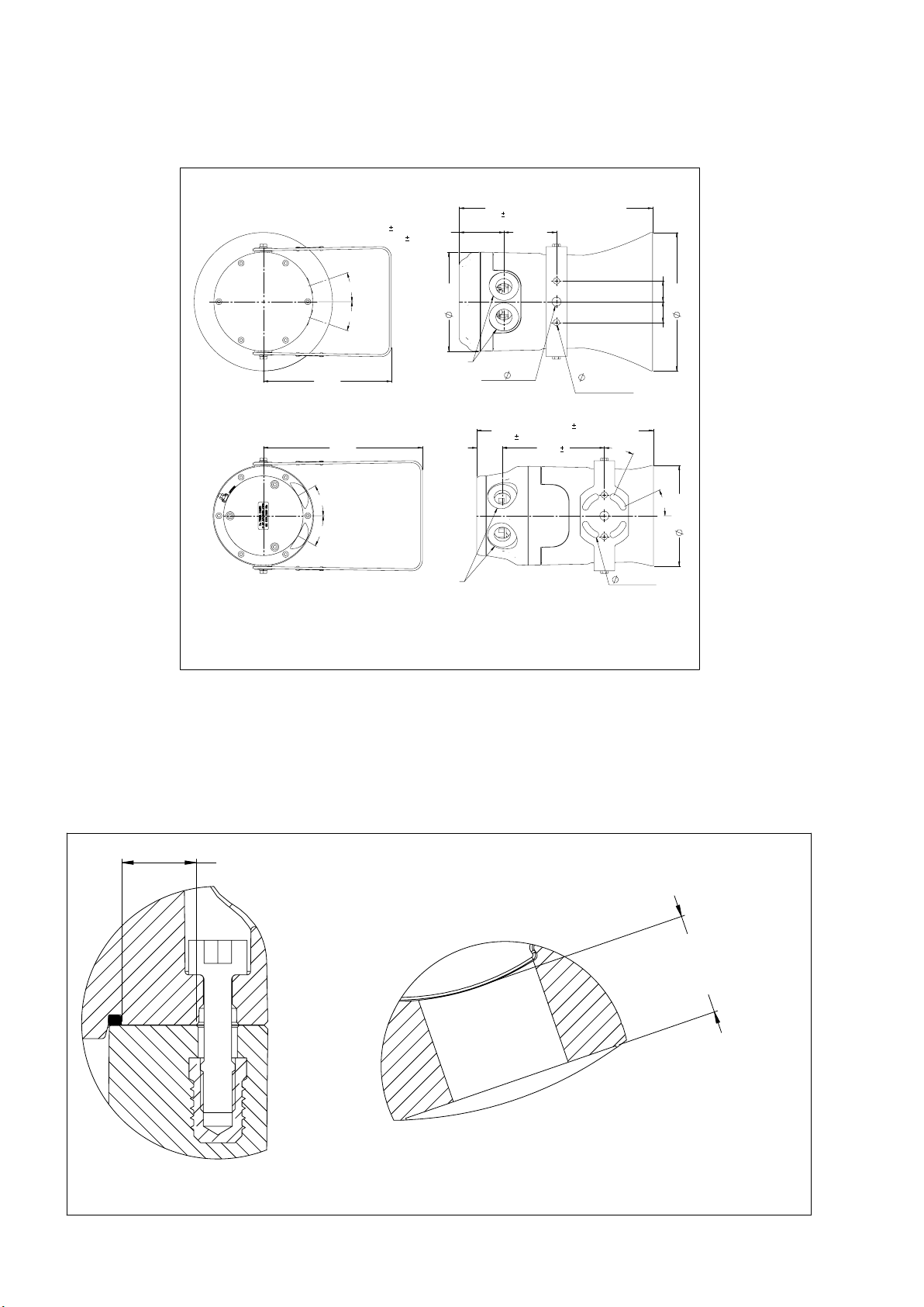
General arrangement
Ex d LONG FLARE VERSION
WITH STANDARD BRACKET
64.5
1 (POS. 1 & 2)
1 (POS. 3)
68.0
280 ±3
3 FOR SHORT FLARE VERSION
208
75.90 ±2
POS. 1
19°
POS. 3
19°
POS. 2
2 ENTRIES MAX.
185 ±2
Ex de SHORT FLARE VERSION
WITH OPTIONAL SWIVEL BRACKET
230 ±2
30°
30°
2 ENTRIES MAX.
FOR Ex d UNIT, POSITION 3 IS USED IF ONLY
1 x M20 or 1 x 1/2" NPT ENTRY IS REQUIRED
ALL DIMENSIONS ARE COMMON TO ALL UNIT VARIATIONS UNLESS OTHERWISE STATED
ALL DIMENSIONS ARE IN MILLIMETRES
143 ±2
FIXING HOLE
13 ±1
3 FOR LONG FLARE VERSION
323.5
37 ±1
147.5
255.5
2
FIXING HOLES
9 ±1
2 POSITIONS
3
25°
30 ±1
200 ±2
30 ±1
25°
145.5 ±2
9 ±1 TYP.
5.0 Maintenance
During the working life of the unit, it should require little or no maintenance. GRP will resist attack by most acids, alkalis
and chemicals and is as resistant to concentrated acids and alkalis as most metal products.
However, if abnormal or unusual environmental conditions occur due to plant damage or accident etc., then visual
inspection is recommended.
See below diagram for details of the flameproof joints found in the unit. WARNING! – The flameproof joints detailed
below are not intended to be repaired.
FLAMEPATH - 9.5 MIN.
INSIDE SCREW HOLES
Ex d COVER/ENCLOSURE
FLAMEPATH
8 SOUNDER - DB3B TM264 June 2019 www.eaton.com
GLAND ENTRY
18 MIN. WALL THICKNESS
UP TO 2 POSITIONS
CABLE ENTRY
DETAIL

Sounder - DB3B
English
If the unit requires cleaning, then only clean exterior with
a damp cloth to avoid electro-static charge build up.
If a unit fault should occur, then the unit can be repaired
by MEDC.
If you acquired a significant quantity of units, then it
is recommended that spares are also made available.
Please discuss your requirements with the Technical Sales
Engineers at MEDC.
6.0 Certification/approvals
lECEx units
Gas (G) certified units
Certified to IEC60079-0, IEC60079-1 and IEC60079-7
Ex d IIC unit (IEC certification No. lECEx BAS 13.0112X)
Ex db IIC TG (T
Ex de IIC unit (IEC certification No. IECEx BAS 13.0114X)
Ex db eb IIC TG (T
See special conditions for safe use for ambient temperature
ranges and T-ratings.
The IECEx certificate and product label carry the IECEx
equipment protection level marking:
Gb
Where Gb signifies suitability for use in a Zone 1 surface
industries area in the presence of gas.
Gas & Dust (GD) certified units
Certified to IEC60079-0, IEC60079-1, IEC60079-7 and
Ex d IIIC unit (IEC certification No. IECEx BAS 13.0113X)
Ex db IIC TG (T
Ex tb IIIC TD (T
Ex de IIIC unit (IEC certification No. IECEx BAS 13.0115X
Ex db eb IIC TG (T
Ex tb IIIC TD (T
*depending on outer flare type (Short flare – IP65, Long
flare – IP66)
See special conditions for safe use for ambient tempera-
ture ranges and T-ratings.
The IECEx certificate and product label carry the IECEx
equipment protection level markings:
Gb and Db
Where Gb signifies suitability for use in a Zone 1 surface
industries area in the presence of gas.
Db signifies suitability for use in a Zone 21 surface
industries area in the presence of dust.
.) Gb
amb
) Gb
amb.
IEC60079-31
) Gb
amb.
) Db IP6X
amb.
) Gb
amb.
) Db IP65/66*
amb.
ATEX units
Gas (G) certified units
Certified to EN60079-0, EN60079-1 and EN60079-7
Ex d IIC unit (ATEX certification No. Baseefa
13ATEX0229X)
Ex db IIC TG (T
Ex de IIC unit
Ex db eb IIC TG (T
) Gb
amb.
(ATEX certification No. Baseefa 13ATEX0232X)
) Gb
amb.
See special conditions for safe use for ambient temperature
ranges and T-ratings.
The ATEX certificate and product label carry the ATEX group
and category marking:
II 2 G
Where:
Signifies compliance with ATEX
II Signifies suitability for use in surface industries
2 Signifies suitability for use in a zone 1 area
G Signifies suitability for use in the presence of gases
Gas & dust (GD) certified units
Certified to EN60079-0, EN60079-1, EN60079-7 and
EN60079-31
Ex d IIIC unit (ATEX certification No. Baseefa13ATEX0231X)
Ex db IIC TG (T
Ex tb IIIC TD (T
) Gb
amb.
) Db IP6X
amb.
Ex de IIIC unit (ATEX certification No. Baseefa13ATEX0233X)
Ex db eb IIC TG (T
Ex tb IIIC TD (T
) Gb
amb.
) Db IP65/66*
amb.
*depending on outer flare type (Short flare – IP65, Long
flare – IP66).
See special conditions for safe use for ambient temperature
ranges and T-ratings.
The ATEX certificate and product label carry the ATEX
group and category marking:
II 2 GD
Where:
Signifies compliance with ATEX
II Signifies suitability for use in surface industries
2 Signifies suitability for use in a zone 1 area
G Signifies suitability for use in the presence of gases
D Signifies suitability for use in the presence of dust
These units also have the following approvals:
Ingress protection: Ex d & Ex e terminal chambers – IP66
& IP67 to IEC60529
9SOUNDER - DB3B TM264 June 2019 www.eaton.com

Sounder - DB3B
English
7.0 Special conditions for safe use
a) Type DB3B Ex d:
IECEx BAS 13.0112X, IECEx BAS 13.0113X,
Baseefa13ATEX0229X & Baseefa13ATEX0231X
1. For replacement purposes the cover fixing screws
shall be of stainless steel grade A2-70 or stronger.
2. Painting and surface finishes, other than those
applied by the manufacturer, are not permitted.
3. When the unit is used in dust atmospheres (GD
units only) the cable entries used shall be sealed
to maintain the IP6X rating, in accordance with the
applicable installation codes.
4. This apparatus is suitable for use only in ambient
temperatures as follows:
Max. Power rating T
15W -55°C to +55°C T5 T100°C
amb.
-55°C to +85°C T4 T135°C
-55°C to +40°C T6 T85°C
b) Type DB3B Ex de:
IECEx BAS 13.0114X, IECEx BAS 13.0115X,
Baseefa13ATEX0232X & Baseefa13ATEX0233X
1. For replacement purposes the cover xing screws
shall be of stainless steel grade A2-70 or stronger.
2. Painting and surface nishes, other than those
applied by the manufacturer, are not permitted.
3. Not more than one single or multiple strand wiring
lead shall be connected into either side of any terminal,
unless multiple conductors have been joined in a
suitable manner, e.g. two conductors into a single
insulated boot lace ferrule.
4. Leads connected to the terminals shall be insulated
for at least 275V and this insulation shall extend to
within 1mm of the metal of the terminal throat.
5. Minimum creepage and clearance distances between
the terminals and adjacent conductive parts (including
cable entry devices) must be at least 6mm.
6. All terminal screws, used and unused, shall be
tightened down.
7. When the unit is used in dust atmospheres (GD
units only) the cable entries used shall be sealed
to maintain the IP6X rating, in accordance with the
applicable installation codes.
T
G
T
D
8. If used, internal optional earthing material shall be
anti-corrosive.
9. This apparatus is suitable for use only in ambient
temperatures as follows:
Max. Power rating T
15W -50°C to +55°C T5 T100°C
amb.
-50°C to +85°C T4 T135°C
-50°C to +40°C T6 T85°C
T
G
T
D
8.0 Functional safety
Introduction
The DB3B Sounder has been designed for use in
potentially explosive atmospheres and harsh environmental conditions. The glass reinforced polyester
enclosures are suitable for use offshore or onshore,
where light weight combined with corrosion resistance
is required.
The safety function of the Sounder is to provide a predetermined audible warning sound when required if the
correct voltage is applied to the unit. The DC version of
the Sounder is designed to operate on a supply voltage
between 12-48v dc.
Under No fault (Normal) Operating conditions the DB3B
Sounder will provide an audible warning sound when
required by the system.Under fault conditions the failure
mode of the Sounder is a failure to provide an audible
warning sound. For the failure rate associated with this
failure mode please refer to the table below.
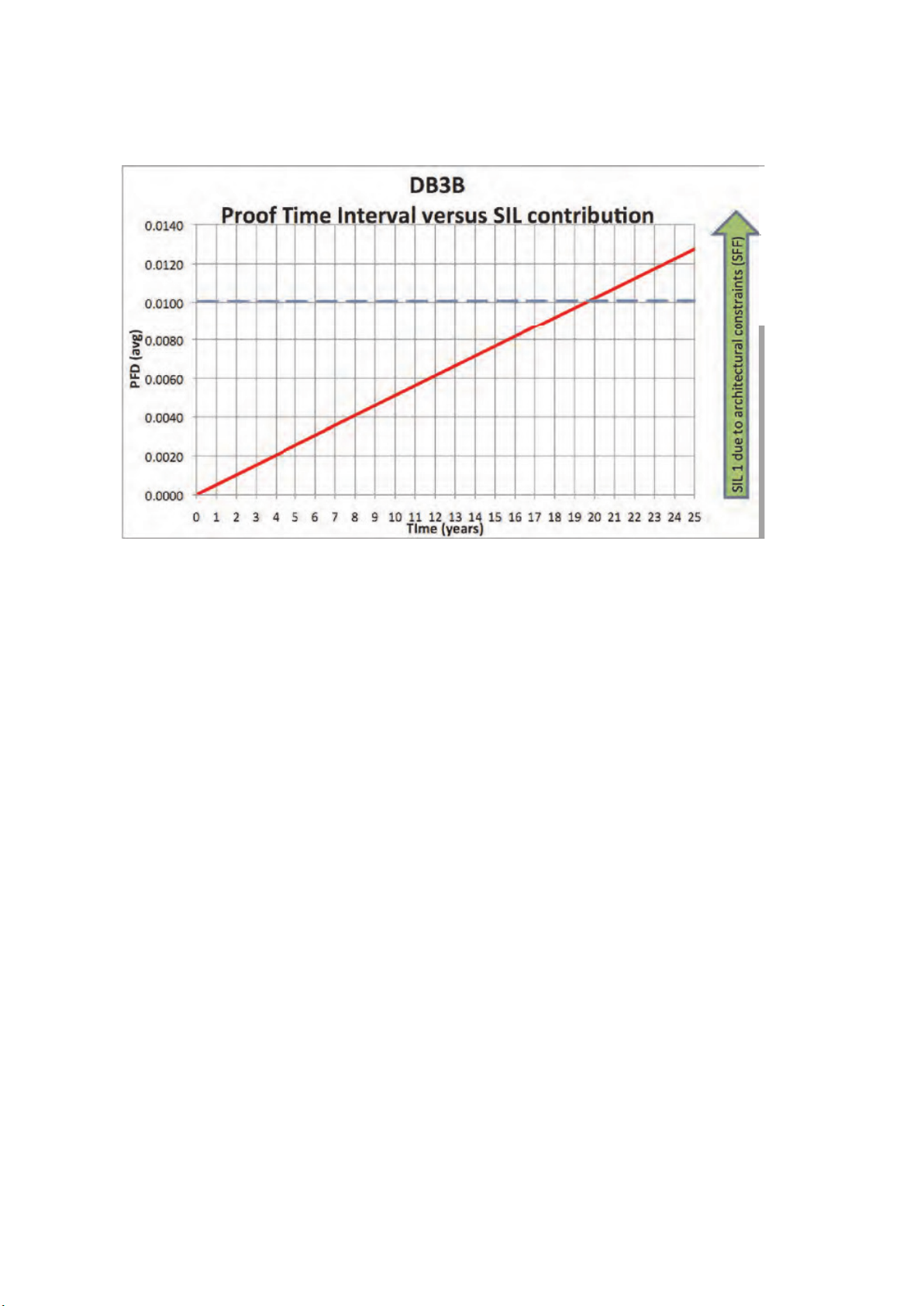
Assessment of functional safety
This Sounder is intended for use in a safety system
conforming to the requirements of IEC61508.
UL has conducted a Failure Modes Effect and Diagnostic.
Analysis (FMEDA) of the DB3B Sounder against the
requirements of IEC 61508-2 using a Proof Test Interval
of 8760hrs.
The results are shown below and are based on Route 1H.
The Sounder is classed as a Type B device.
10 SOUNDER - DB3B TM264 June 2019 www.eaton.com
DB3B Sounder
Safe ty Funct ion of DB3 B Sounder:
To provide a pre-described audible warning sound when required
Summary of Clauses
2/7.4.2 and 2/7.4.4
Architectural constraints
Safe Failure Fraction (SFF)
DB3B Sounder
Single Mode (1oo1)
DB3B Sounder
Redundant Mode (1oo2)
Verdic t
HFT=0 HFT=1 Type B
65.9% 65.9% SIL 1(1oo1)
SIL 2 (1oo2)
Random hardware
failures: [h-1 ]
Random hardware
failures: [h-1 ]
λ
DD
λ
DU
λ
SD
λ
SU
6.5E+09
1.16E- 07
0.00E+00
2.18E-07
6.5E+10
1.16E- 08
0.00E+00
2.18E-0 8
PFD @ PTI = 8760Hrs MTTR = 8 Hrs 5.09E-04 5.09E-05 SIL 3(1oo1)
Average freq. of dangerous failure (high
1.16E- 07 1.16E- 08 SIL 2(1 oo1)
demand-PFH)[h-1]
Hardware safety integrity compliance Route 1
Systematic safety integrity compliance Route 1
Systematic Capability
(SC1, SC2, SC3, SC4)
H
S
SC2
Hardware safety integrit y achieved Limited to: SIL 1 (1oo1) & SIL 2 (1oo2) due to SFF value.
Sounder - DB3B
English
11SOUNDER - DB3B TM264 June 2019 www.eaton.com
Sounder - DB3B
English
Conditions of safe use
The following conditions apply to the installation, operation and maintenance of the assessed equipment. Failure to
observe these may compromise the safety integrity of the assessed equipment:
1. The user shall comply with the requirements given in the manufacturer’s user documentation (This Safety Manual and
Technical manual) in regard to all relevant functional safety aspects such as application of use, installation, operation,
maintenance, proof tests, maximum ratings, environmental conditions, repair, etc;
2. Selection of this equipment for use in safety functions and the installation, configuration, overall validation, maintenance and repair shall only be carried out by competent personnel, observing all the manufacturer’s conditions and
recommendations in the user documentation.
3. All information associated with any field failures of this product should be collected under a dependability
management process (e.g., IEC 60300-3-2) and reported to the manufacturer.
4. The unit should be tested at regular intervals to identify any malfunctions; in accordance with this safety manual.
5. If the product is used in a redundant installation, both hardware safety integrity and systematic safety integrity for
SIL 2 can be achieved. The installation must be such as to ensure sufficient protection against common cause failures
and independence from cascading failures.
12 SOUNDER - DB3B TM264 June 2019 www.eaton.com

Sounder - DB3B
Francais
Contents
1.0 INTRODUCTION . . . . . . . . . . . . . . . . . . . . . . . . . . . . . . . . . . . . . . . . . . . . . . . . . . . . . . . . . . . . . . . . . . . . .14
2.0 MESSAGES ET AVERTISSEMENTS GÉNÉRAUX DE SÉCURITÉ . . . . . . . . . . . . . . . . . . . . . . . . . . . . . .14
3.0 INSTALLATION ......................................................................15
Accès aux bornes ................................................................................ 15
Détail du câblage ................................................................................. 15
Ex d – Détail du cablâge de l’alimentation CA (Types 1 & 2) ......................................... 15
Ex de – Détail du cablâge de l’alimentation CA (Types 3 & 4) ........................................ 16
Ex d & Ex de – Détail du cablâge de I’alimentation CC, 3 phases sans contrôle (Types 5 & 6) ............... 16
Ex d & Ex de – Détail du cablâge de l’alimentation CC, 3 phases sans contrôle (Types 5 & 6) ............... 17
Ex d & Ex de – Alimentation CC, détail de cablâge pour +ve commun deux phases avec contrôle
(configuration standard) (Types 7 & 8) ......................................................... 17
Ex d & Ex de – Détail du cablâge de l’alimentation CC, jusqu’à 3 phases avec ou sans contrôle
(configuration alternative)
(Types 9 & 10) ............................................................................ 18
Ex d – Alimentation CC, jusqu’à 5 phases sélectionnables par l’utilisateur avec sélection de phase hors tension
avec ou sans contrôle. (Type 11) .............................................................. 18
Ex de – Alimentation CC, jusqu’à 5 phases sélectionnables par l’utilisateur avec sélection de phase hors tension
avec ou sans contrôle. (Type 12) .............................................................. 19
4.0 FONCTIONNEMENT .................................................................19
5.0 ENTRETIEN ........................................................................22
6.0 CERTIFICATION/APPROBATIONS ......................................................23
Unités IECEx .............................................................................. 23
Unités certifiées pour les gaz (G) .............................................................. 23
Unités certifiées pour gaz et poussière (GD) ..................................................... 23
Unités ATEX ............................................................................... 23
Unités certifiées pour les gaz (G) .............................................................. 23
Unités certifiées pour gaz et poussière (GD) ..................................................... 23
Ces unités bénéficient également des approbations suivantes : ...................................... 23
7.0 CONDITIONS SPÉCIALES POUR UTILISATION SÉCURISÉE .................................24
8.0 SÉCURITÉ FONCTIONNELLE ..........................................................25
Introduction ............................................................................... 25
Évaluation de sécurité fonctionnelle ............................................................ 25
Conditions d’utilisation sécurisée .............................................................. 25
13SOUNDER - DB3B TM264 June 2019 www.eaton.com

Sounder - DB3B
.
Francais
1.0 Introduction
Cette gamme de générateurs de sons, conçue pour être
utilisée dans des atmosphères gazeuses potentiellement
explosives et poussiéreuses, est disponible dans
des versions adaptées aux groupes de gaz et/ou
poussièressuivants :
La gamme est disponible dans des versions adaptées
pour une utilisation soit avec des groupes de gaz (G), soit
avec des groupes de gaz et poussières (GD).
ote:N l’unité (G) a une puissance de sortie nominale
supérieure de 6 dB à celle d’une unité (GD)
Le boîtier Ex est fabriqué en polyester renforcé de bres
de verre résistant aux UV et ayant une robuste balise
thermoplastique. L’intégration d’un support en acier
inoxydable, des vis du couvercle et des xations garantit
un produit anticorrosion.
Une boîte de raccordement Ex e optionnelle est
disponible (voir section de certication pour davantage
de détails).
Une version non certiée est disponible pour une utilisation
dans des atmosphères non explosives.
2.0 Messages et avertissements généraux de
sécurité
Suivre toutes les instructions et messages de sécurité
contenus dans ce manuel pour permettre l’installation
sécurisée de l’appareil. L’appareil doit être exclusivement
installé et entretenu par du personnel/des installateurs sur
site correctement formés.
I. Pour réduire le risque d’incendie dans des atmosphères
dangereuses et de décharges, ne pas mettre l’appareil
sous tension avant d’avoir terminé l’installation et avant
de l’avoir parfaitement scellé et sécurisé.
II. Pour réduire le risque d’incendie dans des
atmosphères dangereuses et de décharges, maintenir
l’appareil totalement fermé lors de la mise sous
tension du circuit.
III. Avant de retirer le couvercle pour toute opéra-
tion d’installation ou d’entretien, s’assurer que
l’alimentation de l’appareil est isolée.
IV. Une fois l’installation terminée, tester l’appareil pour
s’assurer de son bon fonctionnement.
v. Une fois l’installation terminée, s’assurer qu’une
copie de ce manuel est mise à la disposition de tous
les opérateurs.
VI. Lors de l’installation de l’appareil, se reporter
aux exigences de sélection, d’installation et de
fonctionnement : par exemple les Réglementations
de câblage de l’IEE et le Code national d’électricité
américain (NEC) pour l’Amérique du Nord. Des
exigences nationales et/ou locales supplémentaires
peuvent également s’appliquer.
VII. Les terminaisons de câble doivent être conformes
aux exigences spéciques de l’application requise.
MEDC recommande que tous les câbles et
conducteurs soient correctement identiés. Merci
de se reporter au schéma de câblage fourni dans ce
manuel (ou au schéma spécique fourni avec l’unité).
14 SOUNDER - DB3B TM264 June 2019 www.eaton.com
VIII. S’assurer de n’utiliser que les presse-étoupe spéci-
és ou certiés et vérier que l’ensemble soit bien
protégé et mis à la terre.
IX. S’assurer de n’utiliser que les bouchons obturateurs
spéciés ou certiés pour obturer les entrées de
presse-étoupe non utilisées et vérier que le degré
de protection NEMA/IP de l’unité soit maintenu.
X. MEDC recommande l’utilisation d’une pâte
d’étanchéité telle que HYLOMAR PL32 sur tous
les letages des presse-étoupe et des bouchons
obturateurs et/ou d’une rondelle d’étanchéité adaptée,
an de maintenir le degré de protection IP de l’unité.
XI. Sur les unités Exde, une rondelle d’étanchéité adaptée
doit être montée sur tous les presse-étoupe et les
bouchons obturateurs présents dans le boîtier Exe.
XII. L'utilisateur nal ou l'installateur doit s'assurer que cet
équipement est protégé contre les inuences extérieures qui pourraient nuire à la protection contre les
explosions, ou contacter le fabricant en cas de doute
sur son adéquation à l'environnement dans lequel il
doit être installé.
XIII. Unités Ex d
La borne de terre interne
doit être utilisée pour
une mise à la terre de protection lorsque nécessaire.
Ne pas retirer la tresse de masse de la borne de
terre, quand elle existe.
Pour les unités avec entrées métriques ; la continuité
du presse-étoupe et la mise à la terre peuvent être
réalisés avec une plaque de masse externe en
option. Si la plaque externe est montée, un composé
d’étanchéité de letage comme HYLOMAR PL32
doit être employé pour maintenir la classication IP
de l’appareil.
Unites Ex d e
La tige de mise à la terre interne/ externe doit étre
utilisée pour la mise à la terre de l’équipement
au besoin.
La continuité du presse-étoupe est réalisée si la plaqu
e de mise à la terre interne en option estinstallée.
XIV. MEDC recommande l’utilisation d’éléments de
xation en acier inoxydable lors de I’installation de
l’appareil. S’assurer que tous les écrous, les boulons
et les xations sont sécurisés.
XV. L’unite doit étre positionnée de façon que les débris,
la poussiére ou l’eau ne puissent pas pénétrer dans
le pavillon.
XVI. L’unité doit étre placée de telle sorte que tout objet
solide ne faisant pas partie de l’equipement , se
trouve à un minimum de 40 mm du joint Ex d situé
sur le parcours des ammes.
XVII. L’acheteur doit informer le fabricant de tout impact
externe ou de toute substance agressive
auxquels l’appareil peut être exposé
Sounder - DB3B
Francais
3.0 Installation
L’unité est montée à l’aide de 2 trous de fixation de 9 mm
de diamètre sur l’étrier et/ou support en forme de U. Si
nécessaire, l’unité peut être mise en place au départ à
l’aide du trou central de 13 mm de diamètre prévu dans
l’étrier. L’unité peut ensuite être tournée en position
requise et fixée à l’aide des autres trous.
Si elle est commandée avec l’unité, une option
comportant un étrier de montage pivotant est disponible
pour permettre un réglage supplémentaire en rotation
del’unité.
Les trous de fixation ont été conçus pour accueillir une vis
ou un boulon M8.
Accès aux bornes
Sur les versions Ex d, le couvercle est fixé à l’aide de 6
vis imperdables M5 (à l’aide d’une clé hexagonale/à 6
pans de 4 mm). Une fois que les fixations du couvercle
sont dévissées, il est possible de démonter le couvercle
en le soulevant pour accéder à l’intérieur. Les fixations du
couvercle sont imperdables et restent liées au couvercle.
Sur les versions Ex de, le couvercle amovible est fixé
à l’aide de 3 vis imperdables M5 (à l’aide d’une clé
hexagonale/à 6 pans de 4 mm). Une fois que les fixations
du couvercle sont dévissées, il est possible de démonter
le couvercle en le soulevant pour accéder à l’intérieur. Les
fixations du couvercle sont imperdables et restent liées
au couvercle. Toutes les vis des bornes, utilisées ou non,
doivent être serrées à fond.
Une fois l’opération de terminaison des câbles achevée,
remettre le couvercle en place sur le corps en faisant
attention à ne pas endommager les surfaces de contact.
Serrer uniformément les vis du couvercle. Sur les
versions Ex de certifiées, s’assurer que le couple maximal
est bien appliqué aux vis du couvercle, comme indiqué
sur le couvercle Ex e. S’assurer que le joint torique est
correctement fixé sur le couvercle pendant le remontage.
Sur les versions Ex d certifiées, s’assurer que la distance
maximale nécessaire de 0,04 mm est bien maintenue
entre le couvercle et la base après l’assemblage.
8. Ex de - Alimentation CC, jusqu’à 2 phases
sélectionnables par l’utilisateur avec EOL/contrôle
(configuration standard).
9. Ex d - Alimentation CC, jusqu’à 3 phases
sélectionnables par l’utilisateur avec EOL/contrôle en
option (configuration alternative).
10. Ex de - Alimentation CC, jusqu’à 3 phases
sélectionnables par l’utilisateur avec EOL/contrôle en
option (configuration alternative).
11. Ex d - Alimentation CC, jusqu’à 5 phases
sélectionnables par l’utilisateur avec sélection de
phase hors tension avec ou sans contrôle.
12. Ex de - Alimentation CC, jusqu’à 5 phases
sélectionnables par l’utilisateur avec sélection de
phase hors tension avec ou sans contrôle.
Ex d – Détail du cablâge de l’alimentation CA
(Types 1 & 2)
•
Type 1 : Connecter les fils d’alimentation actif et neutre
aux bornes comme indiqué en détail dans le schéma
de câblage. L’unité est fournie avec la liaison entre
R1 et R0 fixée aux bornes. Lorsque l’alimentation est
appliquée à l’unité, le son de la phase 1 est émis, selon
la sélection choisie sur l’interrupteur DIP à 5 voies.
•
Type 2 : Connecter les fils d’alimentation actif et neutre
aux bornes comme indiqué en détail dans le schéma
de câblage. L’unité est fournie sans liaison entre R1
et R0. Connecter les fils et les interrupteurs distants
aux bornes R0, R1 et R2 comme indiqué. Lorsque
l’alimentation est appliquée initialement à l’unité,
aucun son n’est émis. Lorsque l’interrupteur connecté
à R1 estfermé, le son de la phase 1 est émis, selon
la sélection choisie sur l’interrupteur DIP à 5 voies
de l’ensemble électronique. Lorsque l’interrupteur
connecté à R2 est fermé, c’est le son prélectionné pour
la phase 1 qui est émis. Voir la table des sons 2 pour
les détails des sons présélectionnés.
ote:N Si l’on ferme les deux interrupteurs, aucun son
n’est émis.
Détail du câblage
L’unité est disponible en un certain nombre de configurations de base :
1. Ex d – entrée CA, une seule phase.
2. Ex d – entrée CA, deux phases avec sélection de la
phase hors tension.
3. Ex de – entrée CA, une seule phase.
4. Ex de – entrée CA, deux phases avec sélection de la
phase hors tension.
5. Ex d - Alimentation CC, jusqu’à 3 phases
sélectionnables par l’utilisateur sans contrôle.
6. Ex de - Alimentation CC, jusqu’à 3 phases
sélectionnables par l’utilisateur sans contrôle.
7. Ex d - Alimentation CC, jusqu’à 2 phases
sélectionnables par l’utilisateur avec EOL/contrôle
(configuration standard).
CÂBLAGE
PAR CLIENT
ENTRÉE ACTIVE
SORTIE ACTIVE
ENTRÉE NEUTRE
SORTIE NEUTRE
PHASE 1
PHASE 2
COMMUNE
DE PHASE HORS TENSION
CAVITE DB3B Ex d
ENSEMBLE
ÉLECTRONIQUE
L
L
N
N
R1
R2
R0
BORNES D'ACTIVATION
15SOUNDER - DB3B TM264 June 2019 www.eaton.com
Sounder - DB3B
Francais
Ex de – Détail du cablâge de l’alimentation CA
(Types 3 & 4)
•
Type 3 : Connecter les fils d’alimentation actif et neutre
aux bornes comme indiqué en détail dans le schéma de
câblage. Lorsque l’alimentation est appliquée à l’unité,
le son de la phase 1 est émis, selon la sélection choisie
sur l’interrupteur DIP à 5 voies l’intérieur de la boîte de
raccordement Ex d.
•
Type 4 : Connecter les fils d’alimentation actif et neutre
aux bornes comme indiqué en détail dans le schéma
de câblage. Lorsque l’alimentation est appliquée
initialement à l’unité, aucun son n’est émis. Connecter
les fils et les interrupteurs distants aux bornes R0,
R1 et R2 comme indiqué. Lorsque l’interrupteur
connecté à R1 est fermé, le son de la phase 1 est
émis, selon la sélection choisie sur l’interrupteur DIP
voies de l’ensemble électronique. Lorsque l’interrupteur
connecté à R2 est fermé, c’est le son prélectionné pour
la phase 1 qui est émis. Voir la table des sons pour les
détails des sons 2 présélectionnés.
ENTRÉE ACTIVE
1
SORTIE ACTIVE
2
ENTRÉE NEUTRE
3
SORTIE NEUTRE
PHASE 1 (R1)
PHASE 2 (R2)
COMMUNE (R0)
CÂBLAGE
PAR CLIENT
CAVITE DB3B Ex e
ote:N Si l’on ferme les deux interrupteurs, aucun son
n’est émis.
4
1
2
3
4
Ex d & Ex de – Détail du cablâge de
I’alimentation CC, 3 phases sans contrôle
(Types 5 & 6)
Ce type peut être configuré d’un certain nombre de
façons differentes selon les exigences. Selection de
tonalité indépendante pour toutes les 3 phases via les
3 commutateurs DIP 5 séquences OFF montés sur
l’ensemble électronique :
•
Système à 2 fils (une phase) : Connecter les fils
d’alimentation positif et négatif aux bornes comme
indiqué en détail dans le schéma de càblage.
•
Système à 2 fils (deux phases, polarité inversée) :
Connecter les fils d’alimentation positif et négatif aux
bornes comme indiqué en détail dans le schéma de
càblage. La seconde phase est produite en inversant la
polarité de l’alimentation de l’unité.
•
Système à 3 fils (deux phases, point commun
+ve) : Connecter les 3 fils d’alimentation aux bornes
comme indiqué en détail dans fe schéma de câblage
(1 filcommun +ve et 2 fils -ve). La phase 1 est produite
lorsque l’alimentation est appliquée entre la borne
commune +ve et la borne -ve de la phase 1. La phase 2
est produite lorsque l’alimentation est appliquée entre
la borne commune +ve et la borne -ve de la phase 2.
•
Système à 3 fils (deux phases, point commun -ve) :
Connecter les 3 fils d’alimentation aux bornes comme
indiqué en détail dans le schéma de câblage (2 fils +ve
et 1 fil commun -ve). La phase 1 est produite lorsque
l’alimentation est appliquée entre la borne +ve de la
phase 1 et la borne commune -ve. La phase 2 est
produite lorsque l’alimentation est appliquée entre la
borne +ve de la phase 2 et la borne commune - ve.
•
Système à 4 fils (trois phases, point commun -ve) :
Connecter les 4 fils d’alimentation aux bornes comme
indiqué en détail dans le schéma de càblage (3 fils +ve
et 1 fil commun -ve). La phase 1 est produite lorsque
l’alimentation est appliquée entre la borne +ve de la
phase 1 et la borne commune -ve. La phase 2 est
produite lorsque l’alimentation est appliquée entre la
borne +ve de la phase 2 et la borne commune - ve.
La phase 3 est produite lorsque l’alimentation est
appliquée entre la borne +ve de la phase 3 et la borne
commune -ve.
Toutes les versions sont alimentées par des bornes pour
permettre les connexions en boucle d’entrée et de sortie
des fils d’alimentation.
Remarque : si une résistance EOL est specifiée sur
une unité CC, elle sera montée en standard sur les
bornes 5 & 6 dans la boîte de raccordement Exd (voir
ci-dessous). Repositionner l’EOL comme requis pour
d’autres configurations.
Lors du positionement de la résistance de fin de ligne
(EOL), assurez-vous qu’il y est un espace libre de 14mm
entre le corps de la résistance et les terminaux et que
la résistance ne soit pas en contact avec le PCB ou
leboitier.
16 SOUNDER - DB3B TM264 June 2019 www.eaton.com
Sounder - DB3B
Ex d & Ex de – Détail du cablâge de l’alimentation CC, 3 phases sans contrôle (Types 5 & 6)
Francais
DB3B CONFIGURATION CC
PHASE UNIQUE
PHASE 1 +VE EN ENTRÉE
PHASE 1 -VE EN ENTR
NON UTILISÉ
NON UTILISÉ
PHASE 1 +VE EN SORTIE
PHASE 1 -VE EN SORTIE
NON UTILISÉ
NON UTILISÉ
DB3B CONFIGURATION CC POSITIF
COMMUN DEUX PHASES
COMMUNE +VE EN ENTRÉE
PHASE 1 -VE EN ENTR
NON UTILISÉ
PHASE 2 -VE EN ENTR
COMMUNE +VE EN SORTIE
PHASE 1 -VE EN SORTIE
NON UTILISÉ
PHASE 2 -VE EN SORTIE
E
É
E
É
R1
Ex d
DB3B CONFIGURATION CC DEUX PHASES
AVEC POLARITÉ INVERSÉE
Ex d
Ex d
Ex de
1
E
É
R1
Ex de
1
1
2
2
3
3
4
4
5
1
6
2
7
3
8
4
1
2
2
3
3
4
4
5
1
6
2
7
3
8
4
DB3B CONFIGURATION CC NÉGATIF
COMMUN DEUX PHASES
PHASE 1 +VE EN ENTRÉE
COMMUNE -VE EN ENTR
NON UTILISÉ
PHASE 2 +VE EN ENTR
PHASE 1 +VE EN SORTIE
COMMUNE -VE EN SORTIE
NON UTILISÉ
PHASE 2 +VE EN SORTIE
PHASE 1 +VE / PHASE 2 -VE EN ENTRÉE
PHASE 1 -VE / PHASE 2 +VE EN ENTR
PHASE 1 +VE / PHASE 2 -VE EN SORTIE
PHASE 1 -VE / PHASE 2 +VE EN SORTIE
Ex d
Ex de
1
É
E
E
É
R1
1
2
2
3
3
4
4
5
1
6
2
7
3
8
4
COMMUNE -VE EN ENTR
COMMUNE -VE EN SORTIE
É
E
NON UTILISÉ
NON UTILISÉ
NON UTILISÉ
NON UTILISÉ
DB3B CONFIGURATION CC NÉGATIF
PHASE 2 +VE EN ENTRÉE
PHASE 3 +VE EN ENTR
PHASE 1 +VE EN ENTR
PHASE 2 +VE EN SORTIE
PHASE 3 +VE EN SORTIE
PHASE 1 +VE EN SORTIE
COMMUN TROIS PHASES
Ex de
1
1
2
2
3
3
4
4
5
R1
1
6
2
7
3
8
4
Ex d
Ex de
1
É
E
É
E
É
E
R1
1
2
2
3
3
4
4
5
1
6
2
7
3
8
4
Ex d & Ex de – Alimentation CC, détail de
cablâge pour +ve commun deux phases avec
contrôle (configuration standard) (Types 7 & 8)
Raccorder jusqu’à 4 câbles d’alimentation aux bornes
comme illustré en détail dans le schéma de câblage. La
phase 1 est produite lorsque l’alimentation est appliquée
entre la borne commune +ve et la borne -ve de la phase 1.
La phase 2 est produite lorsque l’alimentation est
appliquée entre la borne commune +ve et la borne -ve de
la phase 2.
La fonctionnalité de contrôle est obtenue lorsque
l’alimentation est connectée aux bornes M1 & M2.
Remarque : les bornes contrôlées ne dépendent pas de
la polarité
DB3B CONFIGURATION CC POSITIF
COMMUN DEUX PHASES AVEC CONTRÔLE
Ex de
Ex d
COMMUNE +VE / M1 EN ENTRÉE
PHASE 1 -VE EN ENTR
M2 EN ENTR
PHASE 2 -VE EN ENTR
É
É
É
COMMUNE +VE / M1 EN SORTIE
PHASE 1 -VE EN SORTIE
M2 EN SORTIE
PHASE 2 -VE EN SORTIE
E
E
E
1
2
3
4
5
6
R1
7
8
FONCTIONALITÉ DE CONTRÔLE UNIQUEMENT
DISPONIBLE AVEC RÉSISTANCE MONTÉE
1
2
3
4
1
2
3
4
17SOUNDER - DB3B TM264 June 2019 www.eaton.com
Sounder - DB3B
Francais
Ex d & Ex de – Détail du cablâge de
l’alimentation CC, jusqu’à 3 phases avec ou
sans contrôle (configuration alternative)
(Types 9 & 10)
Remarque : cette configuration alternative doit être
spécifiée lors de la commande de l’unité.
Ce type peut être raccordé soit comme une configuration
–ve commun trois phases ou, si une résistance EOL facultative est spécifiée, comme un système –ve commun
double phase avec contrôle.
•
Système à 4 fils (trois phases, point commun
+ve) : Connecter les 4 fils d’alimentation aux bornes
comme indiqué en détail dans le schéma de câblage
(1 fil commun +ve et 3 fils -ve). La phase 1 est produite
lorsque l’alimentation est appliquée entre la borne
DB3B CONFIGURATION CC
POSITIF COMMUN TROIS PHASES
Ex d
Ex de
COMMUNE +VE EN ENTRÉE
PHASE 1 -VE EN ENTR
PHASE 3 -VE EN ENTR
PHASE 2 -VE EN ENTR
COMMUNE +VE EN SORTIE
PHASE 1 -VE EN SORTIE
PHASE 3 -VE EN SORTIE
PHASE 2 -VE EN SORTIE
É
E
É
E
E
É
R1
1
1
2
2
3
3
4
4
5
1
6
2
7
3
8
4
commune +ve et la borne -ve de la phase 1. La phase 2
est produite lorsque l’alimentation est appliquée entre
la borne commune +ve et la borne -ve de la phase 2.
La phase 3 est produite lorsque l’alimentation est
appliquée entre la borne commune +ve et la borne -ve
de la phase 3.
•
Système à 4 fils (deux phases, point commun -ve
avec contrôle) : connecter jusqu’à 4 fils d’alimentation
aux bornes comme illustré en détails dans le schéma
de câblage. La phase 1 est produite lorsque la tension
est appliquée aux bornes -ve commun et +ve phase 1.
La phase 2 est produite lorsque la tension est
appliquée aux bornes -ve commun et +ve phase 2.
La fonctionnalité de contrôle est obtenue lorsque
l’alimentation est connectée aux bornes M1 & M2.
Remarque : les bornes contrôlées ne dépendent pas de
la polarité
DB3B CONFIGURATION CC NÉGATIF
COMMUN DEUX PHASES AVEC CONTRÔLE
Ex d
Ex de
PHASE 2 +VE EN ENTRÉE
M1 EN ENTR
PHASE 1 +VE EN ENTR
COMMUNE -VE / M2 EN ENTR
PHASE 2 +VE EN SORTIE
M1 EN SORTIE
PHASE 1 +VE EN SORTIE
COMMUNE -VE / M2 EN SORTIE
É
E
É
E
E
É
R1
1
1
2
2
3
3
4
4
5
1
6
2
7
3
8
4
Ex d – Alimentation CC, jusqu’à 5 phases
sélectionnables par l’utilisateur avec sélection
de phase hors tension avec ou sans contrôle.
(Type 11)
Connecter les fils d’alimentation positif (+ve) et négatif
(-ve) aux bornes comme indiqué en détail dans le
schéma de câblage. Lorsque l’alimentation est appliquée
initialement à l’unité, aucun son n’est émis. Connecter
les fils et les interrupteurs distants aux bornes R0 à
R5 comme indiqué. Lorsque l’interrupteur connecté
à R1 est fermé, le son de la phase 1 est émis, selon
la sélection choisie sur l’interrupteur DIP à 5 voies de
l’ensemble électronique. Lorsque l’un quelconque des
autres interrupteurs connectés aux bornes R2 à R5 est
fermé, c’est le son présélectionné pour les phases 2 à 5
qui est émis. Voir la table des sons 2 pour les détails des
sons présélectionnés.
ote:N Si l’on ferme plus d’un interrupteur à la fois, aucun
son n’est émis.
Si une résistance (R1) est montée, la fonctionnalité de
contrôle est obtenue lorsque la polarité de l’alimentation
est inversée.
FONCTIONALITÉ DE CONTRÔLE UNIQUEMENT
DISPONIBLE AVEC RÉSISTANCE MONTÉE
+VE EN ENTRÉE
+VE EN SORTIE
-
VE EN ENTRÉE
-
VE EN SORTIE
PHASE 1
PHASE 2
PHASE 3
PHASE 4
PHASE 5
COMMUNE
CÂBLAGE
PAR CLIENT
CAVITE DB3B Ex d
R1 - RÉSISTANCE EOL EN OPTION
T1
T2
T3
R1
T4
R1
R2
R3
R4
R5
R0
18 SOUNDER - DB3B TM264 June 2019 www.eaton.com
Sounder - DB3B
Francais
Ex de – Alimentation CC, jusqu’à 5 phases
sélectionnables par l’utilisateur avec sélection
de phase hors tension avec ou sans contrôle.
(Type 12)
Connecter les fils d’alimentation positif (+ve) et négatif
(-ve) aux bornes comme indiqué en détail dans le
schéma de câblage. Lorsque l’alimentation est appliquée
initialement à l’unité, aucun son n’est émis. Connecter
les fils et les interrupteurs distants aux bornes R0 à
R5 comme indiqué. Lorsque l’interrupteur connecté
à R1 est fermé, le son de la phase 1 est émis, selon
la sélection choisie sur l’interrupteur DIP à 5 voies de
l’ensemble électronique. Lorsque l’un quelconque des
autres interrupteurs connectés aux bornes R2 à R5 est
fermé, c’est le son présélectionné pour les phases 2 à 5
qui est émis. Voir la table des sons 2 pour les détails des
sons présélectionnés.
ote:N Si l’on ferme plus d’un interrupteur à la fois, aucun
son n’est émis.
Si une résistance (R1) est montée, la fonctionnalité de
contrôle est obtenue lorsque la polarité de l’alimentation
est inversée.
CÂBLAGE
PAR CLIENT
+VE EN ENTRÉE / SORTIE
-
VE EN ENTRÉE / SORTIE
PHASE 1 (R1)
PHASE 2 (R2)
PHASE 3 (R3)
PHASE 4 (R4)
PHASE 5 (R5)
COMMUNE (R0)
CAVITE DB3B Ex e
R1 - RÉSISTANCE EOL EN OPTION DANS
CAVITE Ex d
1
2
3
4
1
2
3
R1
4
4.0 Fonctionnement
Le générateur de sons est disponible en diverses versions
de tension d’entrée CA et en une seule version de
tension d’entrée CC.
Pour les versions CA, la tension nominale de
fonctionnement est indiquée sur l’étiquette de l’unité et la
tolérance sur la tension d’alimentation est de ±10%.
Pour les versions CC, la plage des tensions d’entrée
absolues va de 11,0 Vcc à 57,6 Vcc.
Dans le cas d’une résistance EOL avec une valeur
comprise entre 700Ω et 2KΩ, la tension maximale devrait
être limitée à 28,8 V cc ; dans le cas d’une résistance
EOL avec une valeur comprise entre 470Ω et 700Ω, la
tension maximale devrait être limitée à 26 V cc.
L’unité est équipée d’une commande du volume qui
est placée sur la face supérieure de la carte de circuit
imprimé de l’ensemble électronique. Le volume maximal
est obtenu lorsque cette commande est complètement tournée dans le sens des aiguilles d’une montre.
Lorsqu’elle est tournée complètement dans le sens
contraire, l’unité n’émet aucun son.
Attention : Ne pas tenter de tourner la commande de
volume au-delà des limites de son mouvement car cela
pourrait endommager l’unité.
Phases
Pour toutes les versions, un interrupteur DIP à 5 voies
sélectionne chaque fois la phase nécessaire. Les réglages
correspondant aux phases standards sont indiqués dans
la table ci-après :
19SOUNDER - DB3B TM264 June 2019 www.eaton.com
 Loading...