

Eaton DALI Installation Manual
P1
Document 9850-000521-00
Introduction
The DALI control panel provides complete
control of pre-programmed lighting scenes
within a DALI lighting control system. The
adaptable design allows you to choose from
a range of button combinations, which can be
tted and changed at any time. Where tted,
raise and lower buttons compliment the usual
selection buttons to allow immediate changes to
the intensity of any scene.
DALI Control Panel
Installation guide
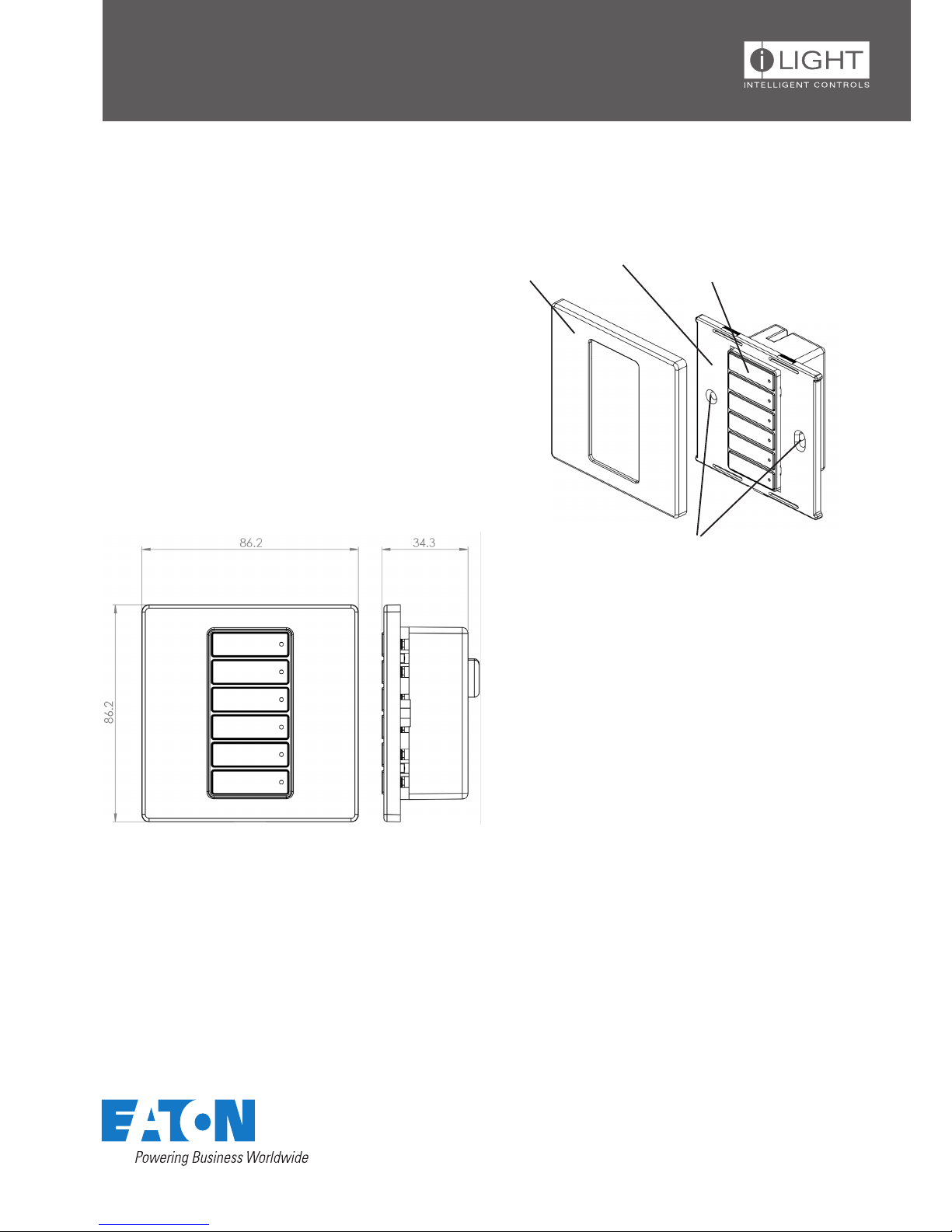
Supplied parts
Front Cover
Back Plate
Button Assembly
Screw holes for attaching
to wall box
Dimensions
The DALI control panel ts into a single gang UK style
wall box with a minimum internal depth of 47mm.
With control panel disassembled (see above), use the
two supplied long screws to secure the back plate to
the wall box.
Fixing to a wallbox
P2
Document 9850-000521-00
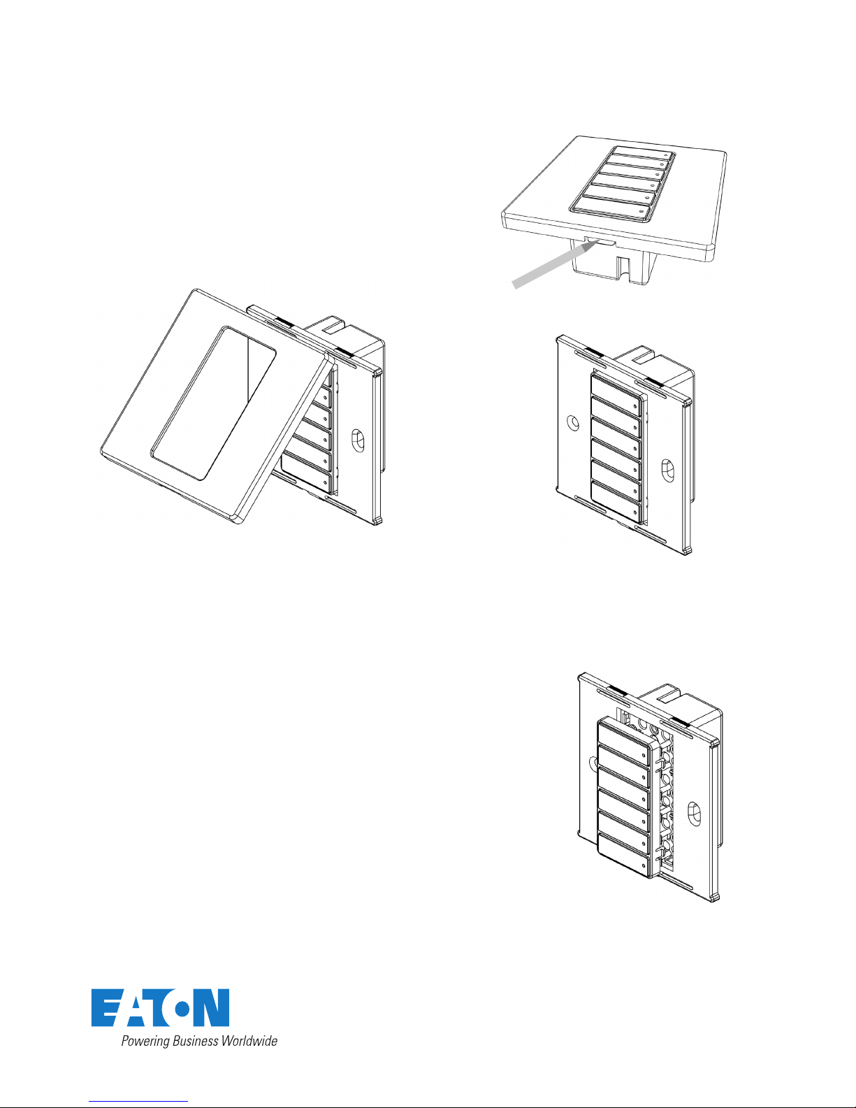
Removing Face Plate from the DALI Control Panel
1. On the underside of the face plate, beneath the lower buttons, locate the small central recess. Carefully insert a
small implement (such as a pen or screwdriver) into the recess and lever the front cover gently away from the back
plate.
Changing buttons
The DALI control panel allows you to change the buttons in order to
customize its appearance.
1. Remove the face plate as illustrated.
2. Locate the four clips (two on each side) of the button frame. Carefully
press in all four clips to disenage the button frame and pull the frame away
from the main body.
3. You can now remove the buttons from the frame and replace them (and
the frame), as necessary.
4. With the new buttons in place within the frame, align its clips with the
four holes of the main body and press it into place so that all four clips
click as they lock.
3. Store face plate safe from damage.
2. Unclip the face plate from the back plate.
 Loading...