

Eaton D85 Series Instructions Manual
IL04906001E
Instructions for D85 Series Alternating Relays
READ INSTRUCTIONS BEFORE INSTALLING OR OPERATING THIS DEVICE. KEEP FOR FUTURE REFERENCE.
!
WARNING
Potentially hazardous voltages are present. Turn off all power supplying
this equipment before connecting or disconnecting wiring.
Installation & Wiring
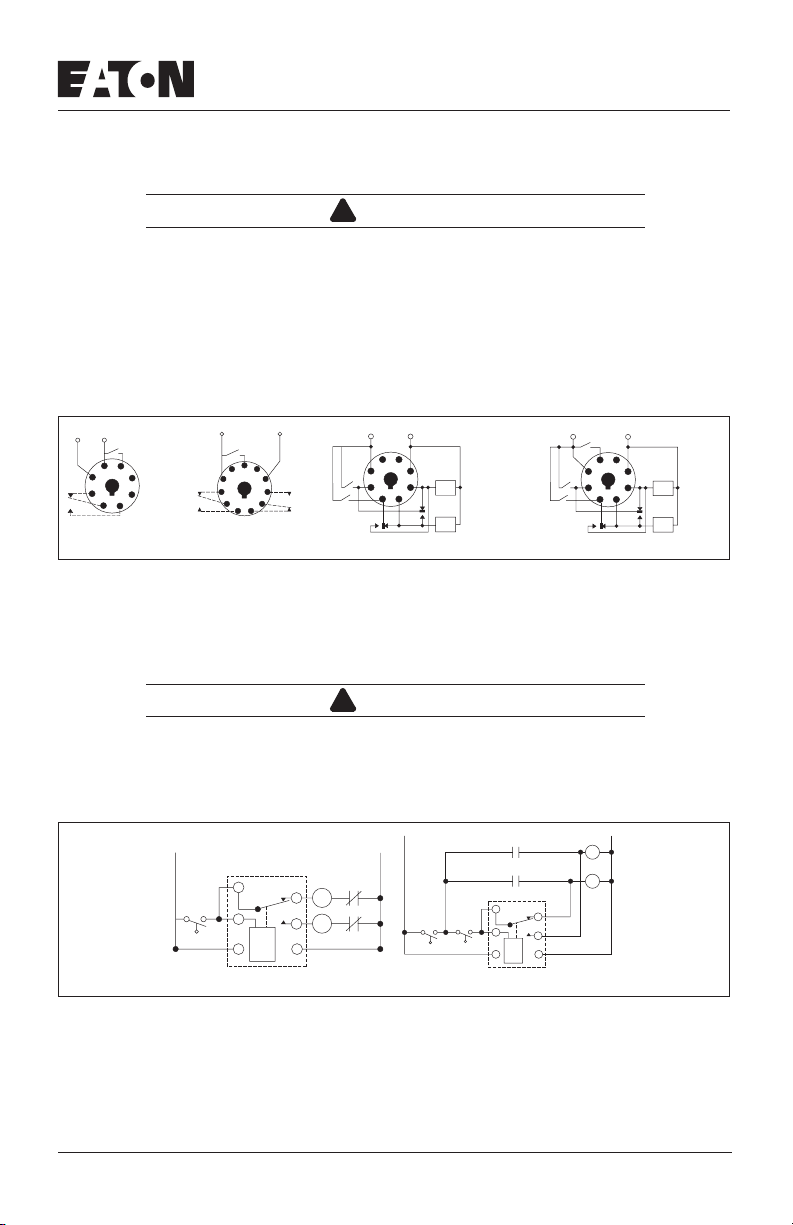
Mount the appropriate 8 or 11 pin octal socket in a suitable enclosure. Wire the socket per one of the
diagrams in Figure 1. Any type of switch (float, manual, timing relay, pressure, or one with an isolated
contact) can be used.
If you are using the same Control Voltage for both the Alternating Relay and the two loads, you
NOTE:
must add a jumper between Terminals 1 & 5 on the SPDT unit or Terminals 2, 6 & 10 on the
DPDT unit. If using multiple switches on the DPDT cross-wired units, check to see the proper
sequence of switch closures is followed, i.e., LEAD before LAG, STOP before LEAD, etc.
Input
Voltage
L2
L1
Control
Switch
4
5
3
6
2
7
1
8
Load A: Pin 2
Load B: Pin 8
SPDT
Input
Voltage
Control
Switch
6
75
48
39
210
1
11
Load A: Pins 3 or 11
Load B: Pins 1 or 9
DPDT
L2L1
Input
Voltage
L1 L2
4
5
36
Lag
27
1
8
Lead
DPDT Cross-Wired
Load
B
Load
A
DPDT Cross-Wired for 3 Switches
Figure 1. Wiring Diagrams
If the unit has the low-profile selector switch, set this switch to “ALTERNATE” for normal operation. In
this mode, the unit will operate as a normal Alternating Relay, alternating between the two loads on
each subsequent closing and opening of the control switch. Setting the selector switch to either “LOAD
A” or “LOAD B” will lock the unit to either one of the loads. By locking the Alternating Relay to one load,
the other load can be removed for service without rewiring the first load for continuous operation.
Input
Voltage
L1 L2
Stop
4
5
36
Lag
27
1
8
Lead
Load
B
Load
A
!
WARNING
When the selector switch is locked in either the LOAD A or LOAD B
position, it does not disconnect voltage from the equipment to be serviced.
Typical Installations
SPDT and DPDT Alternating Relays
L1
1
Control
Switch
5
4
Standard Installation
SPDT
L1
L2
O/L
2
M1
O/L
8
M2
3
Off
Control
Switch
M2
M1
SPDT
1
2
5
8
4
3
Anti-Bounce Installation
L2
M2
M1
Figure 2. Typical Installations for SPDT and DPDT Alternating Relays
In the OFF state (Standard Installation), the Control Switch is open, the Alternating Relay is in the
LOAD A position, and both loads (M1 & M2) are off. When the Control Switch closes, it energizes the
first load (M1). The red LED marked “LOAD A” glows. As long as the Control Switch remains closed,
M1 remains energized. When the Control Switch opens, the first load (M1) is turned off and the Alternating Relay toggles to the LOAD B position. When the Control Switch closes again, it energizes the
second load (M2). The red LED marked “LOAD B” glows. When the Control Switch opens, the second
Effective 03/07 1
IL04906001E
load (M2) is turned off, the Alternating Relay toggles back to the LOAD A position, and the process can
be repeated again. On relays with DPDT contacts, two pilot lights can be used for remote indication of
LOAD A or LOAD B status.
To eliminate any bounce condition of the Control Switch, the addition of a second switch (OFF) along
with two auxiliary contacts is recommended as shown in the Anti-Bounce Installation.
DPDT Cross-Wired Alternating Relays
L1
Cross-Wired
Lag
2
8
Lead
1
3
M1
M2
7
6
L1
L2
O/L
O/L
Off
M2
M1
Cross-Wired
Lag
2
Lead
1
3
Standard Installation Anti-Bounce Installation
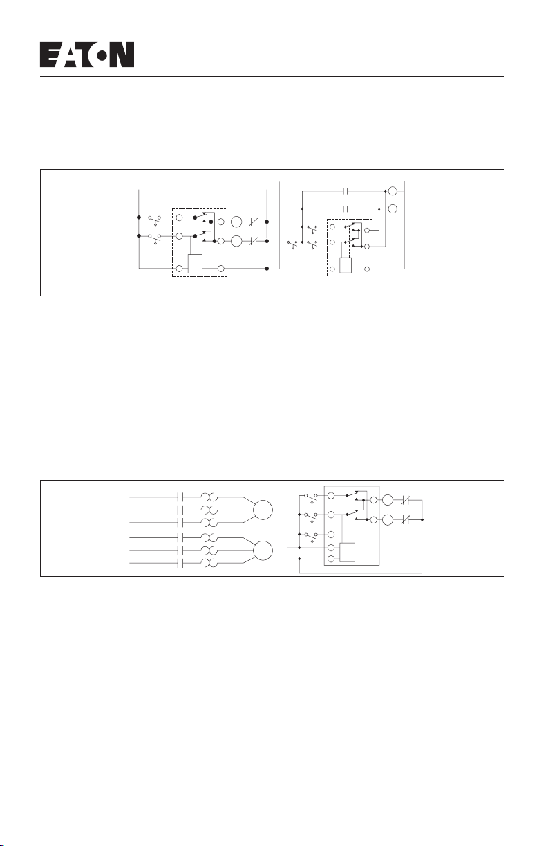
Figure 3. Typical Installations for DPDT Cross-Wired Alternating Relays
In the OFF state, both the LEAD Control Switch and the LAG Control Switch are open, the Alternating
Relay is in the LOAD A position, and both loads are off. When the LEAD Control Switch closes, it energizes the first load (M1). The red LED marked “LOAD A” glows. As long as the LEAD Control Switch
remains closed, M1 remains energized. If the LAG Control Switch closes, it energizes the second load
(M2). When the LAG Control Switch opens, the second load (M2) is turned off. When the LEAD Control
Switch opens, the first load (M1) is turned off and the Alternating Relay toggles to the LOAD B position. When the LEAD Control Switch closes, it turns on the second load (M2). The red LED marked
“LOAD B” glows. If the LAG Control Switch closes, it will energize the first load (M1). When the LAG
Control Switch opens, the first load (M1) is turned off. When the LEAD Control Switch opens, the second load (M2) is turned off, the Alternating Relay toggles back to the LOAD A position, and the process can be repeated again.
To eliminate any bounce condition of the Control Switch, the addition of a second switch (OFF) along
with two auxiliary contacts is recommended as shown in the Anti-Bounce Installation.
DPDT Cross-Wired for Three-Switch Applications
Lag
L1
L2
L3
L1
L2
L3
M1
M1
M1
M2
M2
M2
Motor
Motor
1
2
Switch
2
Lead
Switch
1
Stop
Switch
L1
L2
4
3
6
L2
M2
M1
8
7
6
O/L
M1
8
O/L
M2
7
Figure 4. Typical Installations for DPDT Cross-Wired Relays for Three-Switch Applications
In the OFF state, all three switches are open, the Alternating Relay is in the LOAD A position, and both
loads are off. No action happens with the Alternating Relay or either load when the STOP Switch
closes. When the LEAD Switch closes, Load #1 (M1) turns on. When the LAG Switch closes, Load #2
(M2) turns on. Both loads remain on as long as all three switches are closed.
When the LAG Switch opens, Load #2 (M2) remains on because the STOP Switch is still closed. When
the LEAD Switch opens, Load #1 (M1) remains on because the STOP Switch is still closed. When the
STOP Switch opens, both Load #1 (M1) and Load #2 (M2) are turned off simultaneously. The Alternating Relay toggles to the LOAD B position. The entire cycle is then repeated, but with Load #2 (M2)
energized first followed by Load #1 (M1).
This type of operation is known as “Sequence On – Simultaneously Off (S.O.S.O.)” — the two loads
are energized sequentially, but remain on together until the STOP switch is opened.
If both the STOP Switch and LEAD Switch fail to close and turn on the first load, both loads will be
turned on simultaneously when the LAG Switch is closed.
Troubleshooting
If the unit fails to operate properly, check that all connections are correct per the appropriate wiring
diagram. If problems continue, contact EATON TRC 1-800-809-2772 for assistance.
Effective 03/07 2
 Loading...