

Eaton ATC-900 Instruction Booklet
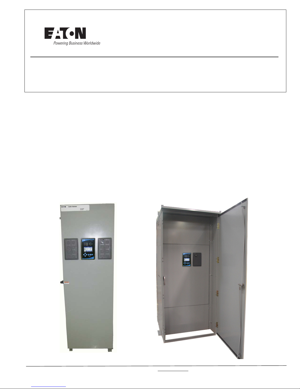
O & M Manual for 40-1200A (480/600 Vac)
ATC-900 3-Position, Open/Closed
Transition Contactor Based Transfer Switch
Instruction Booklet
Description Page
Introduction . . . . . . . . . . . . . . . . . . . . . . . . . . .
Receiving, Handling, and Storage . . . . . . . . . . . .
Equipment Description . . . . . . . . . . . . . . . . . . . .
Installation and Wiring . . . . . . . . . . . . . . . . . . . .
Operation . . . . . . . . . . . . . . . . . . . . . . . . . . . . .
Testing and Problem Solving . . . . . . . . . . . . . . . .
Adjustments . . . . . . . . . .
Maintenance . . . . . . . . . . . . . . . . . . . . . . . . . . .
Renewal Parts Guide . . . .
ATC-900 Controlled ATS Quick Start Instructions . . . . . . . .
. . . . . . . . . . . . . . . . . . . . . . . .23
. . . . . . . . . . . . . . . . . . . . . . . .25
. . . . . . . 2
. . . . . . . 6
. . . . . . . 7
. . . . . . .14
. . . . . . .20
. . . . . . .21
. . . . . . .24
26
IB140036EN For more information visit: www.eaton.com
Instruction Booklet
Cat No: ATC9C3X31200XRU
Style No:
ASSEMBLED IN MEXICO
WITH U.S. COMPONENTS 30 - 43465
ITEM: 001
PIECE: 001
CS#: 123456
J050412234
Volts: 480
Poles: 3
Amps: 1200
Phase: 3
Hertz: 60
Wire: 3/4
GO No: ABC0123
OF: 001
Page 2 Effective: October 2014
O&M Manual for 40-1200A (480/600 Vac) ATC-900 3-Position,
Open/Closed Transition Contactor Based Transfer Switch
Section 1: Introduction
WARNING
READ AND UNDERSTAND THE INSTRUCTIONS CONTAINED HEREINAFTER BEFORE ATTEMPTING TO UNPACK, ASSEMBLE, OPERATE,
OR MAINTAIN THIS EQUIPMENT.
HAZARDOUS VOLTAGES ARE PRESENT INSIDE TRANSFER SWITCH
ENCLOS
INJURY. FOLLOW PROPER INSTALLATION, OPERATION, AND MAINTENANCE PROCEDURES TO AVOID THESE VOLTAGES.
TR
BOOK IS DE
PLATE RATINGS. OPERATION OUTSIDE OF THESE RATINGS MAY
CAUSE
BODILY INJURY, AND/OR PROPERTY DAMAGE. ALL RESPONSIBLE
PERSONNEL SHOULD LOCATE THE DOOR MOUNTED EQUIPMENT
NAMEPLATE AND BE FAMILIAR WITH THE INFORMATION PROVIDED
ON THE NAMEPLATE. A TYPICAL EQUIPMENT NAMEPLATE IS
SHOWN IN FIGURE 1.
URES THAT CAN CAUSE DEATH OR SEVERE PERSONAL
ANSFER SWITCH EQUIPMENT COVERED BY THIS INSTRUCTION
SIGNED AND TESTED TO OPERATE WITHIN ITS NAME-
THE EQUIPMENT TO FAIL RESULTING IN DEATH, SERIOUS
1.1 Preliminary Comments and Safety Precautions
This technical document is intended to cover most aspects associated with the installation, application, operation, and maintenance of the Automatic Transfer Controller (ATC-900) controlled
contactor base
(A). It is provided as a guide for authorized and qualified personnel only. Please refer to the specific WARNING and CAUTION in
Section 1.1.2 before proc
by the purchaser regarding a particular installation, application, or
maintenance activity, please contact an authorized Eaton sales
representative or the installing contractor.
1.1.1 Warranty and Liability Information
No warranties, expressed or implied, including warranties of fitness for a particular purpose of merchantabilit
arising from course of dealing or usage of trade, are made regarding the information, recommendations and de
her
ein. In no event will Eaton be responsible to the purchaser or
user in contract, in tort (including negligence), strict liability or
otherwise for any special, indirect, incidental or consequential
damage or loss whatsoever, including but not limited to damage
or loss of use of equipment, plant or power system, cost of capital, loss of power, additional expenses in the use
power facilities, or claims against the purchaser or user by its
customers resulting from the use of the information and descriptions contained herein.
1.1.2 Safety Precautions
All safety codes, safety standards, and/or regulations must be
strictly observed in the installation, operation, and maintenance
of this device.
d
ATS with ratings from 40 through 1200 amperes
eeding. If further
information is required
y, or warranties
scriptions contained
xisting
of e
Figure 1. Typical Automatic Transfer Switch (ATS) Equipment
Nameplate.
All possible contingencies that may arise du
ring installation, oper-
ation, or maintenance, and all details and variations of this equip-
do no purport to be covered by these instructions. If further
ment
information is desired by the purchaser re
garding a particular
installation, operation, or maintenance of particular equipment,
please contact an authorized Eaton Sales Representative or the
installing contractor.
For more information visit: www.eaton.com IB140036EN
WARNING
THE WARNINGS AND CAUTIONS INCLUDED AS PART OF THE PROCEDURAL STEPS IN THIS DOCUMENT ARE FOR PERSONAL SAFETY
AND PROTECTI
OF A TYPICAL WARNING LABEL HEADING IS SHOWN ABOVE TO
FAMILIARIZE PERSONNEL WITH THE STYLE OF PRESENTATION.
THIS WILL HELP TO INSURE THAT PERSONNEL ARE ALERT TO
WARNINGS, WHICH APPEAR THROUGHOUT THE DOCUMENT. IN
ADDITION, WARNINGS AND CAUTIONS ARE ALL UPPER CASE AND
BOLDFACE.
ON OF EQUIPMENT FROM DAMAGE. AN EXAMPLE
CAUTION
COMPLETELY READ AND UNDERSTAND THE MATERIAL PRESENTED
IN THIS DOCUMENT BEFORE ATTEMPTING INSTALLATION, OPERATION, OR APPLICATION OF THE EQUIPMENT. IN ADDITION, ONLY
QUALIFIED PERSO
WORK ASSOCIATED WITH THIS EQUIPMENT. ANY WIRING
INSTRUCTIONS PRESENTED IN THIS DOCUMENT MUST BE FOLLOWED PRECISELY. FAILURE TO DO SO COULD CAUSE PERMANENT
EQUIPMENT DAMAGE.
NS SHOULD BE PERMITTED TO PERFORM ANY
O&M Manual for 40-1200A (480/600 Vac) ATC-900 3-Position,
Source 1
Source 2
Load
LOGIC
PANEL
POWER
PANEL
VOLTAGE SELECTION
& TRANSFORMER PANEL
Open/Closed Transition Contactor Based Transfer Switch
Instruction Booklet
Effective: October 2014 Page 3
1.2 General Information
Transfer switches are used to protect critical electrical loads
against loss of power. The load’s Source 1 power source is
backed up by a Source 2 power source. A transfer switch is
connected to both the Source 1 and Source 2 power sources and
supplies the load with power from one of the two sources. In the
event that power is lost from Source 1, the transfer switch transfers the load to the Source 2 power source. This transfer is automatic. Once Source 1 power is restored, the load is
automatically trans
(Figure 2).
f
erred back to the Source 1 power source
and the Source 2 power source fails while the Source 1 power
source is still unavailable, the ATS remains connected to the
Source 2 power source.
ATSs automatically perform the transfer function and include
thre
1. A power contactor to connect and disconnect the load to
2. Solenoids to make the transfer of the main contacts from
3. Intelligence/supervisory circuits
elements:
e basic
nd fr
om either power source.
a
source to source.
condition of the power sources and thus provide the intelli-
to const
gence necessary for the switch and related circuit operation.
antly monitor the
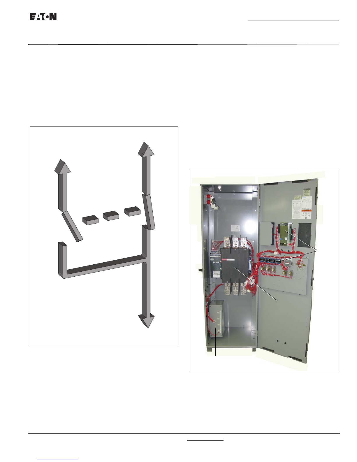
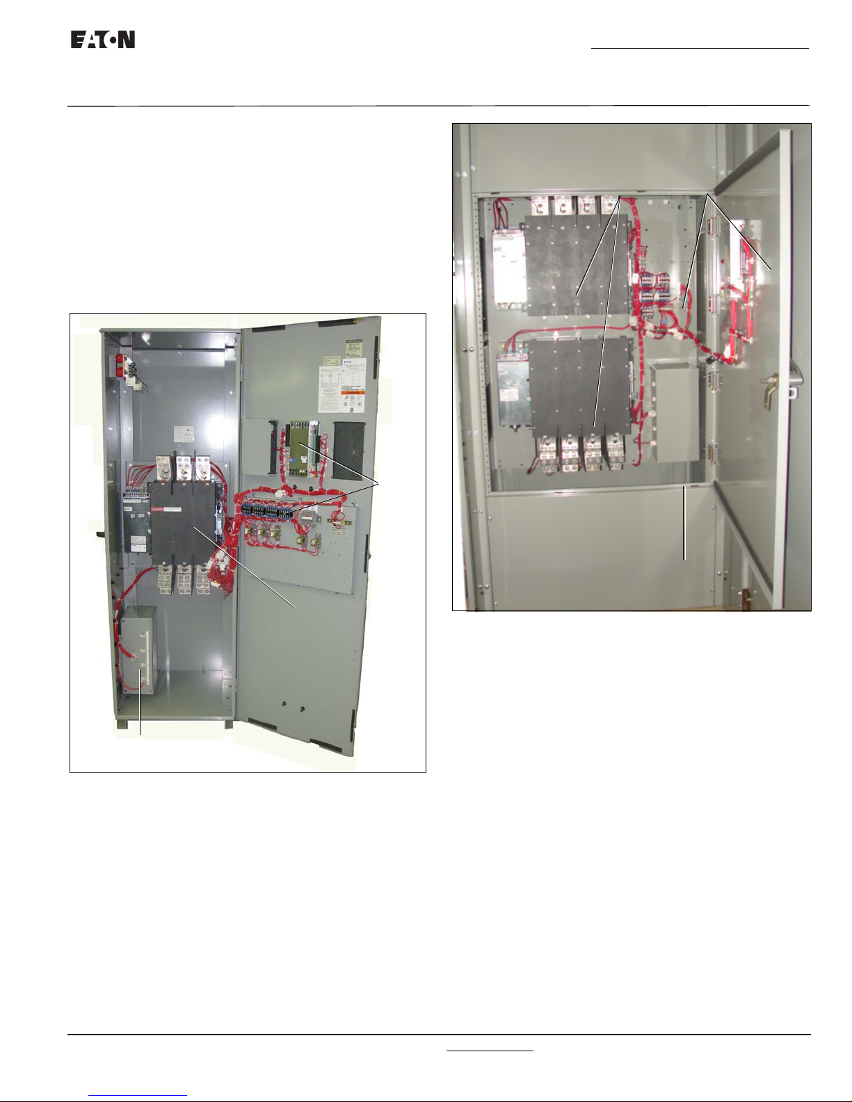
1.2.1 Design Configuration
The Eaton contactor based ATS is a compact design that uses a
power contactor to transfer essential loads from one power
source to another (Figure 3 [1200A]).
Figure 2. Typical Load Transfer Switch Schematic (Contactor
Type).
In ATS equipment, the switch’s intelligence system initiates the
er when the Source 1 power fails, falls below, or rises
transf
above a preset voltage. If the Source 2 power source is a
standby generator, the ATS initiates generator startup and transfers to the Source 2 power source when sufficient generator
age is available. W
volt
automatically transfers back and initiates generator shutdown.
In the event the Source 1 power source fails and the Source 2
power source does not appear, the ATS remains connected to
the Source 1 power source until the Source 2 power source does
appear. Conversely, if connected to the Source 2 power source
hen Source 1 power is restored, the ATS
Figure 3. Typical 1200A Open Transition ATS.
The Eaton contactor based ATS is designed with easy installation
and
simplified maintenance in mind. Three main panels comprise
the contactor based ATS design:
1. Power panel;
2. Voltage selection and transformer panel; and
3. Microprocessor-based logic panel.
IB140036EN For more information visit: www.eaton.com
LOGIC
PANEL
POWER
PANEL
VOLTAGE SELECTION
& TRANSFORMER PANEL
Instruction Booklet
LOGIC
PANEL
POWER
PANEL
VOLTAGE SELECTION
& TRANSFORMER PANEL
AT C 9 C3 X 3 1200 X R U
1to2 3 45 6 7 8 9to
12 13 14 15
to
Page 4 Effective: October 2014
O&M Manual for 40-1200A (480/600 Vac) ATC-900 3-Position,
Open/Closed Transition Contactor Based Transfer Switch
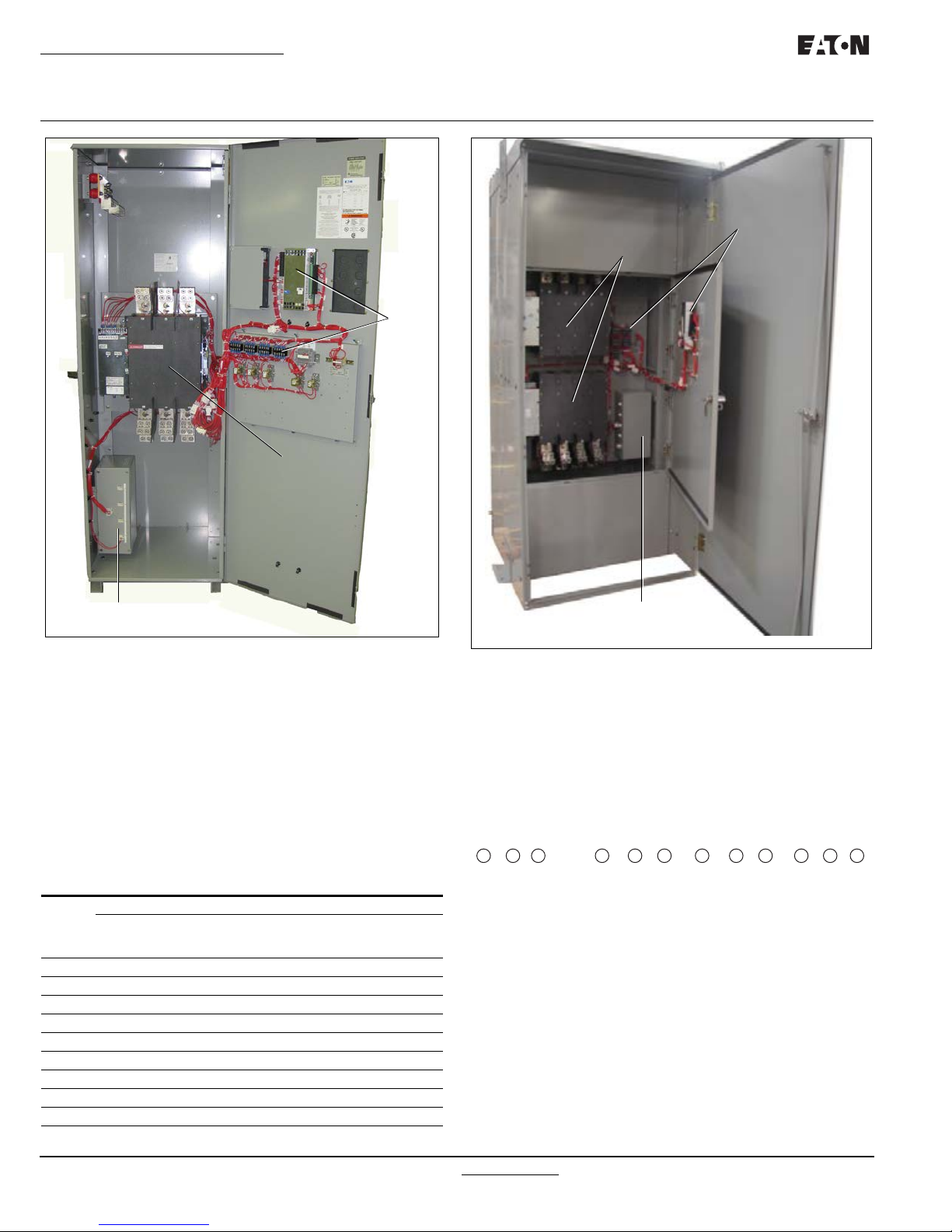
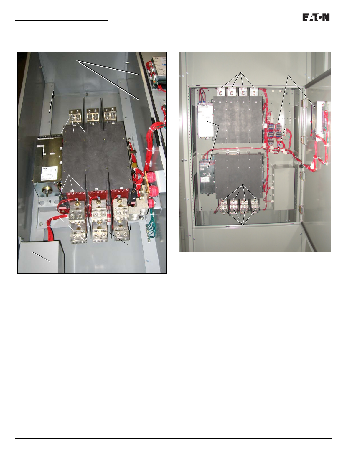
Figure 4A. Open Transition Contactor Based ATS (1200A).
Each panel is independently mounted with interconnecting wiring
terminated at the connector receptacles on the ATC-900 Controller.
For open transition contactor based transfer switch, enclosure
ied
mounting is simplif
gated (teardrop) mounting holes on top a
by utilizing mounting flanges with elon-
n
d floor mount (wall
supported) flanges with two standard mounting holes on the bottom.
For close transition contactor based transfer switch, enclosure is
standing and
free
cific mounting and modification details.
is seismic approved. Refer to Section 4 for spe-
Table 1. Withstand Ratings.
UL 1008 WITHSTAND AND CLOSE-ON RATINGS (kA)
480 Vac 600 Vac
Switch
Rating
(Amps)
100A 50,000 65,000 50,000 65,000
200A 50,000 65,000 50,000 65,000
260A 50,000 65,000 50,000 65,000
320A 50,000 65,000 50,000 65,000
400A 50,000 65,000 50,000 65,000
600A 50,000 65,000 50,000 65,000
800A 50,000 65,000 50,000 65,000
1000A 50,000 65,000 50,000 65,000
1200A 50,000 65,000 50,000 65,000
Any
Breaker
(Amps)
Specific
Breaker
Amps)
Breaker
Any
Amps)
Specific
Breaker
Amps)
Figure 4B. Closed Transition Contactor Based ATS (1200A)
1.3 ATS Catalog Number Identification
Transfer switch equipment catalog numbers provide a significant
amount of relevant information that pertains to a particular piece
of equipment. The Catalog Number Identification Table (Table 2)
provides the required interpretation information. An example is
offered here to initially simplify the process.
a
Example: C
The catalog number ATC9C3X31200XRU describes an ATS with
a 3 pole, 3 position Power Contactor mounted on a baseplate
within the enclosure. The intelligence represented by the logic
panel is ATC-900 controller. The continuous current rating of
this equipment is 1200A and applicable at 480 Vac, 60 Hz. The
transfer switch equipment is enclosed in a NEMA 3R enclosure
and is listed for UL applications.
talog Number (circled numbers correspond to position
headings in Table 2).
For more information visit: www.eaton.com IB140036EN

Instruction Booklet
O&M Manual for 40-1200A (480/600 Vac) ATC-900 3-Position,
Open/Closed Transition Contactor Based Transfer Switch
Table 2. Transfer Switch Catalog Number Explanation
POSITIONS 1 TO 2 POSITION 3 POSITION 4 POSITIONS 5 TO 6
BASIC DEVICE SWITCHING DEVICE CONTROL PANEL SWITCHING DEVICE
Automatic Transfer Switch (Open Transition) AT
Automatic Transfer Switch (Closed Transition) CT
POSITION 7 POSITION 8 POSITIONS 9 TO 12 POSITION 13 POSITION 14 POSITION 15
SWITCHING DEVICE
ARRANGEMENT
Fixed Mount X Two (2)40A – 0040 120 Vac/60 Hz A Type 1 S UL/CSA Listing U
150A – 0150 240 Vac/60 Hz W
NUMBER
OF POLES
Three (3)80A – 0080 208 Vac/60 Hz B Type 12 J No Listing X
Contactor C ATC-900 Controller 9 3 Position Power Contactor
AMPERE
RATING
Four (4)100A – 0100 220 Vac/50 Hz G Type 3R R
200A – 0200 380 Vac/50 Hz H
225A – 0225 415 Vac/50 Hz O
260A – 0260 480 Vac/60 Hz X
400A – 0400 600 Vac/60 Hz E
600A – 0600
800A – 0800
1000A – 1000
1200A – 1200
VOLTAGE/
FREQUENCY ENCLOSURE LISTING
Effective: October 2014 Page 5
3 Position w In-Phase to TDN
C3
C5
1.4 Environmental Conditions
1.4.1 Operational Conditions
Normally, an ATS is applied indoors in an electrical equipment
room. In the appropriate enclosure, it can be used for outdoor
applications where the equipment is subject to falling rain, freezing temperatures, and no greater than 90% humidity (non-condensing). The ambient temperature range for operation is
between -20
and 70°C (-4 to 158°F).
1.5 Glossary
With respect to their use within this document and as they relate
to transfer switch and controller operation, the following terminology is defined.
Available
A source is defined as “available” when it is within its unde
age/overvoltage/ underfrequency/overfrequency (if applicable)
setpoint ranges fo
r the nominal voltage and frequency setting.
Connected
Connected is defined as when the input
is shorted by an external
contact or connection.
Failed or Fails
A source is defined as “failed” whe
n it is outside of the applicable voltage and frequency setpoint ranges for the nominal voltage and frequency setting for a time exceeding 0.5 seconds
r the time delay emergency fail (TDEF) time delays expires.
afte
Failsafe
Failsafe is a feature that prevents disconnection from the only
available powe
r source and also forces a transfer or re-transfer
operation to the only available power source.
Source 1
Source 1 is the primary source (normal source, normal power
e, or normal).
sourc
rvolt-
Source 2
Source 2 is the secondary source (emergency source, emergency power source, emergency, standby, or backup source).
Source 1: Failed or Fails
Source 1 is defined as “failed” when it is outside of its undervoltage/overvoltage/ underfrequency/overfrequency (if applicable) setpoint ranges for the nominal voltage and frequency
setting.
Source 2: Failed or Fails
Source 2 is defined as “failed” when it is outside of its undervoltage/overvoltage/ underfrequency/overfrequency (if applicable) setpoint ranges for the nominal voltage and frequency
setting for a time
exceeding 0.5 seconds after the Time Delay
Emergency Fail (TDEF) time delay expires.
Transfer
Transfer is defined as a change of the load connection from the
Source 1
to the Source 2 power source.
Re-Transfer
Re-transfer is defined as a change
of the load connection from
the Source 2 to the Source 1.
Unconnected
Unconnected is defined as when the input is not shorted by an
external c
ontact or connection.
Features
ATC-900 has many features that are available to the user.
The
These features are standard and are available depending on the
type of transfer switch used (i.e. Contactor, Power Case Switch/
Breaker, or Molded Case Switch/Breaker, 2 or 3 position).
Appendix A of the ATC-900 manual has a list of all of the features including any acronyms used along with a brief description. There are many new features in the ATC-900 that are
shown in the ATC-900 manual.
The ATC-900 connections are shown in Figure 16. Some connections, like engine start are wire to a separate terminal block.
IB140036EN For more information visit: www.eaton.com

Instruction Booklet
Page 6 Effective: October 2014
O&M Manual for 40-1200A (480/600 Vac) ATC-900 3-Position,
Open/Closed Transition Contactor Based Transfer Switch
There are three optional accessory items that also interface to
the ATC-900, the DCT module, the I/O Module, and the Ethernet
Module. See the ATC-900 manual for specific instructions on
these modules. A small description of each follows:
The DCT (Direct Current-Current Transformer) Module is a current transformer interface to the ATC-900 allowing current to be
tered along with voltage and frequency that is already inte-
me
grated into the controller. The DCT Module simply secures to the
00 back using four #8 x less than 1/2 inch screws. The
ATC-9
ribbon cable then plugs into J14. When equipped with a DCT
module, the ATC-900 serves as a multifunction power meter and
provides multifunction measurement of most electrical parameters including voltage, current, power
The meter capabilities is specified as a 1% class energy meter.
The information is displayed on the color display on the front of
the ATC-900. Readings can also be monitored through the RS485 modbus on the controller. The DCT is used to measure load
current when selective load shed is enabled. The DCT Module
also has a 24 Vdc input for powering the ATC-900 controller. If
120 VAC and 24 Vdc is supplied to the controller simultaneously, then the 120 Vac will be the powering supply.
The I/O Module (Figure 16B) is an extension of the ATC-900 controller's programmable inputs and outputs. Each I/O Module has
four inputs and four outputs. The inputs a
at 10 ma) connections for various functional inputs. Up to four
modules can be used with the ATC-900 giving the user up to 20
inputs or 20 outputs (including the controller's standard I/Os).
Depending on the options selected with the transfer switch,
some of the I/Os may be required to be fixed from the factory so
that the user cannot change that particular input or output.
The Ethernet Communications Module is
ates as a communicating device in conjunction with a the ATC-
via an Ethernet network. The Ethernet Module provides
900
Ethernet TCP/IP.
, frequency, energy, etc.
re DC wetted (50 Volts
an accessory that oper-
Section 2: Receiving, Handling, and
Storage
2.1 Receiving
Every effort is made to ensure that the ATS equipment arrives at
its destination undamaged and ready for installation. Packing is
designed to protect internal components as well as the enclosure. Care should be exercised, however, to protect the equipment from impact at all times. D
packaging until the equipment is ready for installation.
When the ATS equipment reaches its destination, the customer
should inspect the ship
rough handling and/or external damage that occurred during
transportation. Record any external and internal damage for
reporting to the transportation carrier and Eaton, once a thorough
inspection is complete. All claims should be as specific as possible and include the catalog and General Order numbers.
A shipping label affixed to the shipping container includes a variety of equipment and customer information, such a
Order Number and catalog numbers. Make certain that this information matches other shipping paper information.
Each transfer switch is packed securely with appropriate shipping materials to prevent damage during shipment. Do not
emove or discard the packing material until the equipment is
r
ready for installation.
Once the top packaging is removed from the shipment, the
enclosure door can be opened. A plast
be found in the enclosure, usually attached to the inside of the
enclosure. Important documents, such as test reports, wiring
diagrams, and appropriate instruction leaflets, are enclosed
within the bag and should be filed in a safe place.
ping container for any obvious signs of
2.2 Handling
o not remove the protective
s General
ic bag of documents will
As previously mentioned, ATS equipment is packaged for forklift
movement. Protect the equipment from impact at all times and
DO NOT double stack.
Once the equipment is at the installation location and ready to be
talled, packaging material can be removed and discarded.
ins
Once the enclosure is unbolted from the wooden pallet, it can be
hand moved to its installation position. Be careful not to damage
the top or bottom enclosure mounting flanges. Refer to Section
4 of this manual for specific installation instructions.
2.3 Storage
Although well packaged, this equipment is not suitable for outdoor storage. The equipment warranty
there is evidence of outdoor storage. If the equipment is to be
stored indoors for any period of time, it should be stored with its
protective packaging material in place. Protect the equipment at
all times from excessive moisture, construction dirt, corrosive
conditions, and other contaminants.
It is strongly suggested that the package-protected equipment be
stored in a climat
from -30 to 85°C (-22 to 185°F) and with a relative humidity of
80% or less. DO NOT, under any circumstance, stack other
equipment on top of a transfer switch equipment enclosure,
whether packaged or not.
e-controlled environment with temperatures
will not be applicable if
For more information visit: www.eaton.com IB140036EN
O&M Manual for 40-1200A (480/600 Vac) ATC-900 3-Position,
LOGIC
PANEL
POWER
PANEL
VOLTAGE SELECTION
& TRANSFORMER PANEL
LOGIC
PANEL
POWER
PANEL
VOLTAGE SELECTION
& TRANSFORMER PANEL
Open/Closed Transition Contactor Based Transfer Switch
Section 3: Equipment Description
3.1 General
The ATS consists of three basic panels:
1. The power panel;
2. The voltage selection and transformer panel; and
3. The microprocessor-based logic panel.
These panels are interconnected via connector plugs and
mounted in an enclosure (Figure 5
.
A
& 5B)
Instruction Booklet
Effective: October 2014 Page 7
Figure 5A. Three Basic Panels of an Open Transition ATS
(1200A).
Figure 5B. Three Basic Panels of a Close Transition ATS
(1200A).
3.2 Power Panel
The power panel is used for making load, power, and neutral connections. The power contactor is mounted on a steel baseplate
(Figure 6)
3.2.1 Main Contacts
This ATS incorporates a power contactor. The main contacts
connect and disconnect the load to and from the different power
sources. The power contactor is mechanically and electrically
interlocked to prevent the two sets of main contacts from being
closed simultaneously (applicable for open transition ATS only).
.
IB140036EN For more information visit: www.eaton.com
LOGIC
PANEL
SOURCE 1
LUGS
TRANSFER
MECHANISM
SOURCE 2
LUGS
LOAD
LUGS
GROUND
CONNECTION
VOLTAGE
PANEL
NEUTRAL
CONNECTION
SELECTION
Instruction Booklet
LOGIC
PANEL
SOURCE-1 LUGS
VOLTAGE SELECTION
& TRANSFORMER PANEL
TRANSFER
MECHANISM
SOURCE-2 LUGS
LOAD LUGS
GROUND
CONNECTION
Page 8 Effective: October 2014
O&M Manual for 40-1200A (480/600 Vac) ATC-900 3-Position,
Open/Closed Transition Contactor Based Transfer Switch
Figure 6A. Typical for 1200A Open Transition ATS.
Figure 6B. Typical for 1200A Close Transition ATS.
3.3 Voltage Selection
3.3.1 North American Voltage Selection (120, 208, 240,
480, 600, 60 Hz)
The North American market voltage selection panel consists of
multi-tap transformers, contained in a steel case mounted in the
transfer switch enclosure (Figure 7). The cover has two connectors on it, with the one on the right being selectable depending on
the volta
removed by removing the two front screws and disconnecting the
two plugs. The rear of the transformer enclosure has two flanges
that are inserted into two slots. The voltage is selected by simply
removing the plug from the default selected voltage on the cover
plate and installing the plug to the desired available voltage. Plugs
are provided for 120 to 600 Vac to satisfy any required North
American market application voltage. The factory default position is 480 Vac or 600 Vac. There is a similar selection panel for
internat
ge applied to S1 a
ional voltages.
nd S2. The transformer unit is easily
For more information visit: www.eaton.com IB140036EN
O&M Manual for 40-1200A (480/600 Vac) ATC-900 3-Position,
Open/Closed Transition Contactor Based Transfer Switch
DANGER
WHEN CHANGING THE VOLTAGE SELECTION, THE POWER MUST BE
REMOVED FROM THE TRANSFER SWITCH. ALWAYS VERIFY THAT
NO VOLTAGE IS PRESENT ON EQUIPMENT PRIOR TO SERVICING.
FAILURE TO FOLLOW THIS WARNING COULD LEAD TO DEATH OR
SEVERE INJURY. WHILE ENERGIZED, AN ARC FLASH AND SHOCK
HAZARD EXISTS. CONSULT NFPA 70E AND OSHA GUIDELINES FOR
OPERATOR SAFETY PRIOR TO SERVICING, INSPECTING OR OPERATING EQUIPMENT.
Instruction Booklet
Effective: October 2014 Page 9
Figure 7.North American Market Voltage Selection Terminals
(Shown Connected to the 208 Vac Plug).
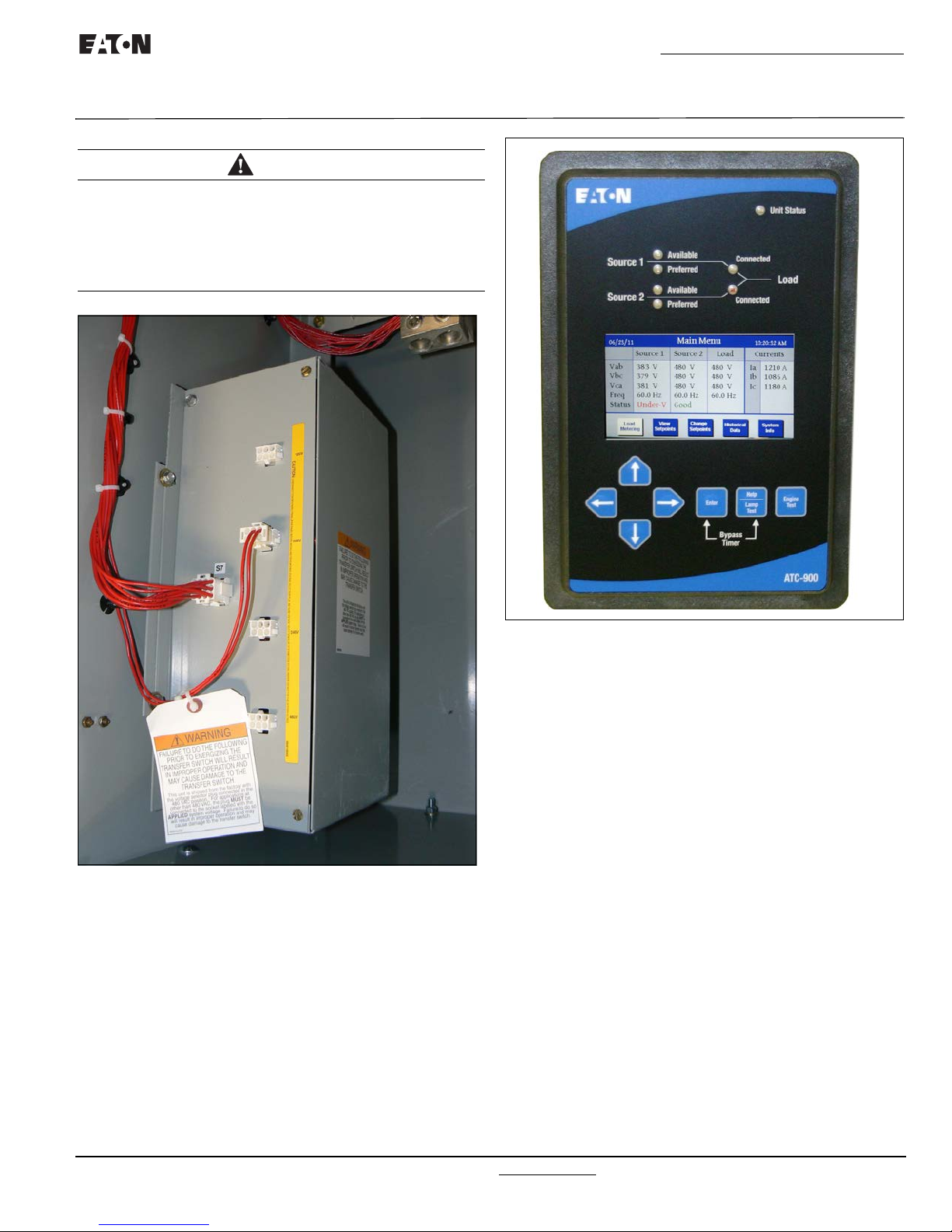
3.4 ATC-900 Logic Panel
The ATC-900 is a microprocessor-based transfer switch logic
control package. The hardware and software of the controller
contain the intelligence/supervisory circuits that constantly monitor the condition of the power sources. It provides the intelligence necessary for the operation of the ATS (Figure 8). It has
r
friendly menus and a color TFT display for easy verification
use
and feature user settings.
Figure 8.
The ATC-900 controller has an operating temperature of
-20 to 70°C (-4 to 158°F).
The controller circuit board is prote
mal coating.
The specifications, under normal operating conditions, are as follows:
■ Tolerance for voltage sensing function: ±1% of full scale.
■ Tolerance for frequency sensing function: ±0.3 Hz of setting.
Please see the ATC-900 controller's Instruction Booklet for new
feat
ATC-900 Logic Control Panel.
ures and instructions.
c
ted by an insulating confor-
3.5 Features and Glossary of Terms
A variety of standard and optional features are available for Eaton
ATSs. All features or combinations of features may not be avail-
able on specific ATSs. All fe
writers Laboratories (UL) listed unless noted.
3.5.1 Operational Simplicity
From installation, to programming, to usage, the ATC-900 was
designed with operational simplicity in mind. Only one style
needs to be considered, regardless of input/output requirements
or system voltages and frequencies. ATC-900 provides the functionality of numerous other devices combined in one package
that mounts in less than 7 by 11 inches of panel space.
The user friendly front panel interface simplifies routine operation, programming, data presentation and setting adjustments. A
large color display provides flexibility and ease of use. The operation of front panel membrane pushbuttons moves the ATC-900
display from function to function or step to step within menus. A
atures a
nd/or accessories are Under-
IB140036EN For more information visit: www.eaton.com

Instruction Booklet
Page 10 Effective: October 2014
O&M Manual for 40-1200A (480/600 Vac) ATC-900 3-Position,
Open/Closed Transition Contactor Based Transfer Switch
single LED at the top of the faceplate provides an immediate indication as to the device’s operational mode. An integrated Help
Mode provides immediate user assistance in the form of English
language message displays through the use of a front panel Help
pushbutton.
The ATC-900 is communications ready, including Modbus 485,
Ethernet (External), and USB for thumb drives (memory sticks).
3.5.2 Features and Glossary of Terms
A variety of programmable features are available to meet a wide
array of application requirements. Individual features or feature
combinations provide the information required to tailor switches
to individual needs.
Unlike earlier controllers, the ATC-900 comes with standard features that are ready to use, with the exception of Closed Transition, In-Phase, Current metering, and Ethernet. Another
advancement is that there are four (4) standard inputs and four
(4) standard outputs that the operator can easily program by
choosing from a wide array of predefined functions. Additional
inputs and outputs can be added in groups of four (4) up to sixteen (16) for a maximum of twenty (20) in total. The inputs are
DC wetted (50 Volts at 10 ma) connections for various functional inputs.
NOTICE
WITH RESPECT TO THEIR USE IN THIS DOCUMENT AND AS THEY
RELATE TO AUTOMATIC TRANSFER SWITCH OPERATION, THE FOLLOWING WORDS OR PHRASES ARE DEFINED:
Options
The only item that is optional for the transfer switch is the closed
ansition optional feature. The switch type
tr
can be programmed. For example, a two position contactor
switch cannot have feature TDN (Time Delay Neutral), as it has
no neutral position available. A motor MCS/MCCB type transfer
switch with motor operator cannot have closed transition as the
switching mechanism is not fast enough and will not meet the
time line.
Standard Feature: In-Phase Type Operation
As shown in the feature list of Appendix A for In-Phase, ther
ee scenarios for In-Phase:
thr
32C= In-Phase default to Load Voltage Decay
32D= In-Phase default to Time Delay Neutral
32F= In-Phase
ges to the In-Phase operation:
There is a setpoint that allows cha
In-Phase = 0 Disables In-Phase (open transition)
In-Phase = 1 Enables In-Phase Defaults to Alarm
(no Transfer)
In-Phase = 2 Enables In-Phase Defaults to Open
(Time Delay Neutral for 3 position switche
With the setpoint at "2", a two position contactor, the switch
will transfer, if
The three position will allow the use of TDN.
no synchronisation occurs, to the other source.
n
also dictates what
e are
Closed Transition Types Operation
Optional Feature 47C: Closed/In-phas
Decay
Closed Transition is a feature that will t
live sources in a make-before-break scheme when performing a
transfer. This achieves a transfer between sources with no
power interruption. Both sources must be synchronized in frequency, phase, and voltage before the transfer is initiated.
In-phase transition is a feature that
two live sources only when the phase difference between the
two sources is near zero. This is an open transition transfer that
prevents in-rush currents from exceeding normal starting currents
in the case where motor loads are being transferred.
Time Delay Load Voltage Decay utilizes the load voltage measurements to sense back EMF that is generated when the transfer switch is in the neutral position. It pr
in either direction if an unacceptable level is sensed as established by a customer programmed level. T
place until the back EMF decays below the acceptable programmed level. This feature has a se
disabling the operation. If disabled, the transfer switch will not
delay in the neutral position and will transfer between the
sources as fast as possible.
Optional Feature 47D: Closed Transition Only
Closed Transition is a feature that will t
live sources in a make-before-break scheme when performing a
transfer.
This achieves a transfer between sources with no power interruption. Both sources must be synchronized in frequency, phase,
and voltage before the trans
If the logic is forced into a fail safe mode (i.e. loss of connected
ce), the logic will per
sour
fer.
Optional Feature 47E: Closed/In-Phase
Neutral
Closed Transition is a feature that will t
live sources in a make-before-break scheme when performing a
transfer. This achieves a transfer between sources with no
power interruption. Both sources must be synchronized in frequency phase, and voltage before the transf
In-phase
two live sources only when the phase difference between the
two sources is near zero. This is an open transition transfer that
prevents in-rush currents from exceeding normal starting currents
in the case where motor loads are being transferred.
Time delay neutral provides a time delay in the transfer switch
neutral pos
place when the load is transferred in either direction to prevent
excessive in-rush currents due to out of phase switching of large
motor loads.
Optional Feature 47F: Closed/Load Voltage Decay
s)
Closed Transition is a feature that will t
live sources in a make-before-break scheme when performing a
transfer. This achieves a transfer between sources with no
power interruption. Both sources must be synchronized in frequency, phase, and voltage before the transfer is initiated.
Time Delay Load Voltage Decay utilizes the load voltage measurements to sense back EMF that is generated when the transfer switch is in the neutral position. It pr
in either direction if an unacceptable level is sensed as estab-
transition is a feature that will allow a
itio
n when both breakers are open. This delay takes
er is initiated.
f
form a load voltage decay open trans-
e Transition/Load Voltage
e
mporarily parallel two
will allow a
ovides
parate setting
e
Transition/T
e
e
ovides
transfer between
a delay in transfer
h
e transfer will not take
mporarily parallel two
mporarily parallel two
er is initiated.
transfer between
mporarily parallel two
a delay in transfer
of enabling or
ime Delay
For more information visit: www.eaton.com IB140036EN

O&M Manual for 40-1200A (480/600 Vac) ATC-900 3-Position,
Open/Closed Transition Contactor Based Transfer Switch
Instruction Booklet
Effective: October 2014 Page 11
lished by a customer programmed level. The transfer will not
take place until the back EMF decays below the acceptable pro
grammed level. This feature has a separate setting of enabling or
disabling the operati
delay in the neutral position and will transfer between the
sources as fast as possible.
Optional Feature 47G: Closed/Time Delay Neutral
Closed Transition is a feature that will temporarily parallel t
live sources in a make-before-break scheme when performing a
transfer This achieves a transfer between sources with no power
interruption. Both sources must be synchronized in frequency,
phase, and voltage before the transfer is initiated.
Time delay neutral provides a time delay
neutral position when both breakers are open. This delay takes
place when the load is transferred in either direction to prevent
excessive in-rush currents due to out of phase switching of large
motor loads.
Two Options for Closed Transition
If closed transition is available on
receive 47 D or all of the other options 47 C, E, F, G which can
be changed by the setpoints to disable or enable the function.
Screen 3 of 3 in the System Setup menu (See section 3.4.1) is
where the user will set the transition types of the switch. If the
switch can perform closed transition the user will set up the setpoints depending on the scenario required as shown below.
Closed Transition only (47D) or
Closed Transition > In-Phase > TDN
Closed Transition > In-Phase > LVD
Closed Transition > TDN
Closed Transition > LVD
The user can disable closed transition and just use the following:
In-Phase > TDN
In-Phase > LVD
Also with Closed Transition and In-Phase disabled:
TDN or LVD
Standard Feature 3: Time Delay Emergency to Normal (TDEN)
TDEN delays the transfer to t
zation of the Normal power source before the transfer is made.
This timer will begin the countdown from its setting value when
the Normal Source becomes available. During the countdown of
this timer, if the Normal Source should become unavailable, the
timer will be aborted. If the Preferred Source is available and the
Emergency Source fails while the TDEN timer is counting down,
the TDEN timer will be bypassed.
Standard Feature 4: Time Delay for Engine Cool-Off (TDEC)
TDEC permits the generator to run under a no-load condition
after a transfer from the generator source has been made. Countdown timing begins when the transfer is completed. In applications where two generators are selected, the same cool-off timer
setting value is used for both.
Display
There are two displays used on the ATC-900. There is the familiar MIMIC display using LEDs (see below) and the color display
using the push buttons for menu operation.
on. If disabled, the transfer switch will not
w
o
in the transf
the switch, t
e Normal Source to permit stabili-
h
er switch
he user will either
Source 1 Connected - Status LED
-
This LED is lit green if Source 1 is connected. This is accomplished by sensing the Source 1 breaker via the S1 closed auxiliary contact.
Source 2 Connected - Status LED
This LED is lit red if Source 2 is connected. This is accomplished
by sensing the Source 2 breaker via the S2 closed auxiliary contact.
Source 1 Available - Status LED
This LED is lit amber if Source 1 meets the criteria for programmed Source 1 setpoints.
Source 2 Available - Status LED
This LED is lit amber if Source 2 meets the criteria for programmed Source 2 setpoints.
Source 1 Preferred - Status LED
This LED is lit red if Source 1 is the preferred source choice.
Source 2 Preferred - Status LED
This LED is lit red if Source 2 is the preferred source choice.
Load Energized - Status LED
This LED is lit red if the load is connected to a source that is
available.
CAUTION
LOAD ENERGIZE LED IS NOT A POSITIVE INDICATION THAT VOLTAGE IS NOT PRESENT ON THE LOAD TERMINALS.
CAUTION
CHANGING THE SYSTEM NOMINAL VOLTAGE OR FREQUENCY SETPOINTS WILL CAUSE PICKUP AND DROPOUT SETPOINTS TO
CHANGE AUTOMATICALLY TO NEW DEFAULT VALUES.
Optional Feature 9B: Maintenance Selector Switch (MSS)
Marked “OFF”, “ON”. This feature provides selector switch disconnection of control to transfer thus allowing testing of the
transfer switch control logic circuitry without initiating load
transfer. Positioning the MSS in the “OFF” position isolates the
control circuit, permitting manual operation of the transfer
switch or testing of logic circuitry without load transfer.
Optional Feature 29G: Auto/Manual Operation
(Available for 3-Position ATS only)
This feature provides 2-position auto/manual selector switch
marked “Auto/Manual” which permits the selection of automatic
or manual operation. Once the selector switch is transferred to
manual mode, manual transfer between Normal (S1), Neutral and
Emergency (S2) can be achieved by operating 3-position selector
switch marked “Normal-OFF-Emergency”.
Optional Feature 29G: Auto/Manual Operation
(Available for 2-Position ATS only)
This feature provides 2-position auto/manual selector switch
marked “Auto/Manual” which permits the selection of automatic
or manual operation. Once the selector switch is transferred to
manual mode, manual transfer between Normal (S1) and Emergency (S2) can be achieved by operating another 2-position
selector switch marked “Normal-Emergency”.
IB140036EN For more information visit: www.eaton.com
 Loading...