

Eaton ATC-600 Instructions For Installation, Operation And Maintenance
Instructions for Installation, Operation
and Maintenance of the
Eaton ATC-600 Automatic
Transfer Switch Controller
Instructional Booklet
Description Page
1. Introduction . . . . . . . . . . . . . . . . . . . . . . . . . . . . . . . 2
2. Hardware Description . . . . . . . . . . . . . . . . . . . . . . . . 7
3. Operator Panel . . . . . . . . . . . . . . . . . . . . . . . . . . . . . 11
4. Operation. . . . . . . . . . . . . . . . . . . . . . . . . . . . . . . . . 14
5. Programming . . . . . . . . . . . . . . . . . . . . . . . . . . . . . . 19
6. Troubleshooting and Maintenance . . . . . . . . . . . . . . . . 22
Appendix A: Status Display Messages . . . . . . . . . . . . . 27
Appendix B: Historical Display Information . . . . . . . . . . 28
Appendix C: Time/Date Display Information . . . . . . . . . 30
Appendix D: ATC-600 Menu Tree . . . . . . . . . . . . . . . 31
Appendix E: Operational Flowcharts . . . . . . . . . . . . . . . 33
IB ATS-1005 For more information visit: www.eaton.com

Instructional Booklet
Page 2 Effective: March 2010
CAUTION
THE ATC-600 IS FACTORY PROGRAMMED FOR A SPECIFIC TRANSFER SWITCH. DO NOT ATTEMPT TO INTERCHANGE ATC-600 CONTROL DEVICES WITHOUT CONSULTING THE FACTORY.
All possible contingencies which may arise during installation,
operation, or maintenance, and all details and variations of this
equipment do not purport to be covered by these instructions. If
further information is desired by purchaser regarding his particular
installation, operation or maintenance of his equipment, the local
Eaton representative should be contacted.
Instructions for Installation, Operation and Maintenance of the
Eaton ATC-600 Automatic Transfer Switch Controller
Section 1: Introduction
1.1 Preliminary Comments and Safety Precautions
This technical document is intended to cover most aspects associated with the installation, application, operation and maintenance
of the ATC-600. It is provided as a guide for authorized and qualified personnel only in the selection and application of the ATC-
600. Please refer to the specific WARNING and CAUTION in Section 1.1.2 before proceeding. If further information is required by
the purchaser regarding a particular installation, application or
maintenance activity, a Eaton representative should be contacted.
NOTICE
DURING CONVERSATIONS WITH EATON CONCERNING TROUBLESHOOTING OR PRODUCT RETURN, THE CUSTOMER MAY BE ASKED
FOR INFORMATION PERTAINING TO THE SOFTWARE VERSION AND
OPTIONS INCLUDED IN THE SPECIFIC UNIT. REFER TO THE “NOTE”
UNDER THE TOPIC “HELP PUSHBUTTON” IN PARAGRAPH 3.4 FOR
INSTRUCTIONS ON HOW TO OBTAIN THIS INFORMATION.
1.1.1 Warranty and Liability Information
NO WARRANTIES, EXPRESSED OR IMPLIED, INCLUDING WARRANTIES OF FITNESS FOR A PARTICULAR PURPOSE OF MERCHANTABILITY, OR WARRANTIES ARISING FROM COURSE OF
DEALING OR USAGE OF TRADE, ARE MADE REGARDING THE
INFORMATION, RECOMMENDATIONS AND DESCRIPTIONS CONTAINED HEREIN. In no event will Eaton be responsible to the purchaser or user in contract, in tort (including negligence), strict
liability or otherwise for any special, indirect, incidental or consequential damage or loss whatsoever, including but not limited to
damage or loss of use of equipment, plant or power system, cost
of capital, loss of power, additional expenses in the use of existing
power facilities, or claims against the purchaser or user by its customers resulting from the use of the information and descriptions
contained herein.
1.1.2 Safety Precautions
All safety codes, safety standards and/or regulations must be
strictly observed in the installation, operation and maintenance of
this device.
WARNING
THE WARNINGS AND CAUTIONS INCLUDED AS PART OF THE PROCEDURAL STEPS IN THIS DOCUMENT ARE FOR PERSONNEL SAFETY
AND PROTECTION OF EQUIPMENT FROM DAMAGE. AN EXAMPLE
OF A TYPICAL WARNING LABEL HEADING IS SHOWN IN REVERSE
TYPE TO FAMILIARIZE PERSONNEL WITH THE STYLE OF PRESENTATION. THIS WILL HELP TO INSURE THAT PERSONNEL ARE ALERT TO
WARNINGS, WHICH MAY APPEAR THROUGHOUT THE DOCUMENT.
IN ADDITION, CAUTIONS ARE ALL UPPER CASE AND BOLDFACE AS
SHOWN BELOW.
CAUTION
COMPLETELY READ AND UNDERSTAND THE MATERIAL PRESENTED IN THIS DOCUMENT BEFORE ATTEMPTING INSTALLATION,
OPERATION OR APPLICATION OF THE EQUIPMENT. IN ADDITION,
ONLY QUALIFIED PERSONS SHOULD BE PERMITTED TO PERFORM
ANY WORK ASSOCIATED WITH THE EQUIPMENT. ANY WIRING
INSTRUCTIONS PRESENTED IN THIS DOCUMENT MUST BE FOLLOWED PRECISELY. FAILURE TO DO SO COULD CAUSE PERMANENT EQUIPMENT DAMAGE.
For more information visit: www.eaton.com IB ATS-1005

Instructions for Installation, Operation and Maintenance of the
Eaton ATC-600 Automatic Transfer Switch Controller
Instructional Booklet
Effective: March 2010 Page 3
1.2 Background
Transfer switches are used to protect critical electrical loads
against loss of power. The load’s normal power source is backed
up by a secondary (emergency) power source. A transfer switch is
connected to both the normal and emergency sources and supplies the load with power from one of these two sources. In the
event that power is lost from the normal source, the transfer
switch transfers the load to the secondary source. Transfer can be
automatic or manual, depending upon the type of transfer switch
equipment being used. Once normal power is restored, the load is
transferred back to the normal power source.
In automatic transfer switch equipment, the switch’s intelligence
system initiates the transfer when normal power fails or falls
below a preset voltage. If the emergency source is a standby generator, the transfer switch initiates generator starting and transfers to the emergency source when sufficient generator voltage is
available. When normal power is restored, the transfer switch
automatically transfers back and initiates engine shutdown.
An automatic transfer switch consists of three basic elements:
1. Main contacts to connect and disconnect the load to and from
the source of power
2. A transfer mechanism to affect the transfer of the main con-
tacts from source to source
3. Intelligence/supervisory circuits to constantly monitor the con-
dition of the power sources and thus provide the intelligence
necessary for the switch and related circuit operation
This manual deals with the third basic element of the automatic
transfer switch, the required intelligence/ supervisory circuits.
Prior to the introduction of ATC-600, this function was performed
by a door mounted logic panel. The logic panel could be the relay
logic type or the solid state logic type. In either case, the panel
consisted of a number of individually mounted and wired devices
offering a limited amount of system flexibility, especially in the
case of the relay logic design. ATC-600 brings intelligence, supervisory and programming capabilities, never before available, to
automatic transfer switch equipment.
1.3 Product Overview
The ATC-600 is a comprehensive, multi-function, microprocessor
based automatic transfer switch controller. It is a compact, selfcontained, panel mounted device designed to replace traditional
relay and solid state logic panels (Figures 1 and 2).
Designed to meet the needs of markets worldwide, ATC-600:
• Is a UL Recognized Component
• Meets Seismic Requirements of Uniform and California Building
Codes (exceeding requirements of worst case Zone 4 levels)
• Complies with UL 991 environmental tests
• Complies with IEC 61000-4-2, 61000-4-3, 61000-4-4, and
61000-4-5
• Complies with CISPR 11, Class A
• Complies with FCC Part 15, Subpart B, Class A
ATC-600 provides an unmatched degree of programmed flexibility
to address the needs of any system. It operates from most system
voltages available worldwide at 50 or 60 Hertz. In addition, a
period of no control power operation is provided. ATC-600 monitors the condition of the 3-phase line-to-line voltage and frequency
of both the Normal and Emergency sources. It can also be programmed for single phase operation. ATC-600 provides the necessary intelligence to insure that the switch operates properly
through a series of programmed sensing and timing functions.
A standard ATC-600 will:
• Monitor Normal and Emergency source voltages and frequen-
cies
• Provide undervoltage monitoring of Normal and Emergency
sources
• Permit customer programming
• Display real time and historical information
• Permit system testing
• Offer Help Screen assistance
• Store customer/factory established parameters in nonvolatile
memory
• Communicate using a PONI
• Provide faceplate source/load status indications
A wide array of additional features are available to address the
most sophisticated system requirements, such as:
• Previously unavailable Load Monitoring and Delayed Transition
• In-phase Transition
1.4 Functions/Features/Options
The primary function of ATC-600 is to accurately monitor power
sources and provide the necessary intelligence to operate a transfer switch in an appropriate and timely manner. In addition,
ATC-600 provides useful present and historical data, reliable twoway communications, and programming through the device’s faceplate or communications option. ATC-600 features proprietary
microprocessor technology to provide and maintain superior precision and versatility during both programming and data access.
1.4.1 Operational Simplicity
From installation to programming to usage, ATC-600 was
designed with operational simplicity in mind. Only one style needs
to be considered, regardless of input/output requirements or system voltages and frequencies. ATC-600 provides the functionality
of numerous other devices combined in one package that mounts
in less than 7 by 11 inches of panel space.
The user friendly front panel interface simplifies routine operation,
programming, data presentation and setting adjustments. An LED
based display provides the flexibility of large character displays for
enhanced visibility. The operation of front panel membrane pushbuttons moves the ATC-600 display from function to function or
step to step within a function. Three LEDs at the top of the faceplate provide an immediate indication as to the device’s operational
mode. An integral Help Mode provides immediate user assistance in
the form of English language message displays through the use of a
front panel Help pushbutton.
With a Product Operated Network Interface (PONI), the ATC-600
is communications ready and compatible with other devices in the
IQ Family of products. The Communication Module (PONI) is available in three versions, the INCOM PONI, RS-232 PONI and PONI
Modem. Reliable two-way communications can be provided over a
twisted pair communications network. With the INCOM PONI,
ATC-600 is compatible with the Eaton IMPACC system.
1.4.2 Standard and Optional Features
A variety of programmable features are available to meet a wide
variety of application requirements. Individual features or feature
combinations provide the intelligence required to tailor switches to
individual needs.
IB ATS-1005 For more information visit: www.eaton.com

Instructional Booklet
Page 4 Effective: March 2010
Instructions for Installation, Operation and Maintenance of the
Eaton ATC-600 Automatic Transfer Switch Controller
The features are factory activated, depending upon customer
requirements. The specific variable setpoints associated with standard and factory activated features are stored in a nonvolatile
memory. Activated feature setpoints are available for customer
adjustment. Any feature not selected and factory activated cannot
be viewed or adjusted.
NOTICE
WITH RESPECT TO THEIR USE IN THIS DOCUMENT AND AS THEY
RELATE TO AUTOMATIC TRANSFER SWITCH OPERATION, THE FOLLOWING WORDS OR PHRASES ARE DEFINED:
Available
A source is defined as available when it is within its undervoltage/
overvoltage/underfrequency/overfrequency (if applicable) setpoint
ranges for the nominal voltage and frequency setting.
Fails
A source is defined as failed when it is outside of its undervoltage/
overvoltage/underfrequency/overfrequency (if applicable) setpoint
ranges for the nominal voltage and frequency setting.
Normal Source
The Normal Source is defined as the source that is preferred. The
Preferred Source setting allows the operator to select Source 1,
Source 2 or NONE as the Preferred Source. If NONE is chosen, the
Preferred Source or the Normal Source will be the source that is
presently attached to the load. If the Preferred Source feature is
not available from the factory, the default is set as being Source 1
as the Preferred and Normal Source.
Emergency Source
The Emergency Source is defined as the source that is not preferred. If NONE is chosen for the Preferred Source setting, the
Emergency Source will be the source that is presently not
attached to the load. Therefore, in this condition after a transfer,
what was the Normal and Emergency Sources will switch
between Source 1 and 2. If the Preferred Source feature is not
available from the factory, the default is set with Source 2 as the
Emergency Source.
Option #
For personnel who are familiar with previous transfer switch controller option specifications, an attempt at equivalence to some of
the features is made.
ATC-600 features with a brief description follow. The actual programmable setpoints for each feature are covered in Section 5.
Standard Feature: Time Delay Engine Start (TDES)
TDES is used where the source is an engine generator. It delays
initiation of the engine start circuit in order to override momentary
power outages and/or fluctuations. This timer and the associated
engine start circuit will operate with or without control power.
There are two separate start circuits, one for each source when
applications of two generators are selected, although the same
TDES timer value is used for both. When one generator is
selected, this timer’s engine start circuit will operate on generator
2 for source 2. If the source that is being transferred to has a generator and that source is already available, the TDES timer is
bypassed.
Standard Feature: Time Delay Normal to Emergency (TDNE)
TDNE delays the transfer to the Emergency Source to permit stabilization of the Emergency power source before the transfer is
made. This timer will begin the countdown from its setting value
when the Emergency Source becomes available. If the Normal
Source should become available during the countdown of this
timer, the timer will be aborted.
Standard Feature: Time Delay Emergency to Normal (TDEN)
TDEN delays the transfer to the Normal Source to permit stabilization of the Normal power source before the transfer is made. This
timer will begin the countdown from its setting value when the
Normal Source becomes available. During the countdown of this
timer, if the Normal Source should become unavailable, the timer
will be aborted. If the Preferred Source is available and the Emergency Source fails while the TDEN timer is counting down, the
TDEN timer will be bypassed.
Standard Feature: Time Delay for Engine Cool-Off (TDEC)
TDEC permits the generator to run under a no-load condition after
a transfer from the generator source has been made. Countdown
timing begins when the transfer is completed. In applications
where two generators are selected, the same cool-off timer setting value is used for both.
Standard Feature: Time Delay Emergency Failure (TDEF)
TDEF is used where at least one source is an engine generator.
TDEF will delay an available source from being declared unavailable in order to override momentary generator fluctuations. This
time delay is only implemented when the load is connected to a
generator source. TDEF is not displayed when the number of generators is zero.
CAUTION
CHANGING THE SYSTEM NOMINAL VOLTAGE OR FREQUENCY SETPOINTS WILL CAUSE PICKUP AND DROPOUT SETPOINTS TO
CHANGE AUTOMATICALLY TO NEW DEFAULT VALUES.
Standard Feature : System Nominal Frequency (NOMF)
There are only two choices for system nominal frequency of the
distribution system, 50 or 60 Hertz. The dropout/pickup, underfrequency and overfrequency upper and lower setting limits are
based on the nominal frequency value.
Standard Feature: System Nominal Voltage (NOMV)
This refers to the standard system nominal RMS line to line voltage. A wide range (120 to 600) of sensing voltage is available to
be programmed. The dropout/pickup, undervoltage and overvoltage upper and lower setting limits are based upon the nominal
voltage value.
Standard Feature: Undervoltage Monitoring for Source 1 (1UVD,
1UVP)
This feature constantly monitors Source 1 for an undervoltage
condition. When the Source 1 voltage drops to a value equal to or
below the undervoltage dropout setting, the source will become
unavailable. The source’s voltage will then have to rise to a value
that is equal to or above the pickup setting to become available
again.
Standard Feature: Undervoltage Monitoring for Source 2 (2UVD,
2UVP)
This feature functions the same as Standard Feature (1UVD,
1UVP), except for Source 2 instead of Source 1.
Standard Feature: Underfrequency Monitoring for Source 2
(2UFD, 2UFP)
This feature functions the same as Optional Feature 26E, except
for Source 2 instead of Source 1.
For more information visit: www.eaton.com IB ATS-1005

Instructions for Installation, Operation and Maintenance of the
Eaton ATC-600 Automatic Transfer Switch Controller
Instructional Booklet
Effective: March 2010 Page 5
Standard Feature: Commit to Transfer During TDNE Timing
(CTDNE)
This feature provides for selection as to whether or not commitment to transfer is desired when Time Delay Normal to Emergency
countdown has begun. If no commitment is chosen and the Normal Source returns to availability when the TDNE timer is counting
down, the transfer is aborted and the engine generator (if applicable) is cooled down.
Standard Feature: Engine Test Mode (TMODE)
This feature provides selection of the type of test that can be initiated by the front panel Engine Test pushbutton. An engine test
without transferring the load to it, or an engine test with a full
transfer of the load to the engine can be chosen. Load testing is
fail-safe. If the generator fails during testing for any reason, the
ATC-600 will signal the transfer switch to return to normal. If disable test mode is chosen, the front panel pushbutton cannot be
used to initiate a test.
Standard Feature: Test Engine Run (TER)
This feature provides selection of the length of time in hours and
minutes that the ATC-600 will enable the generator contacts during an Engine Test that was initiated from the front panel pushbutton or for the plant exerciser feature, if applicable.
Standard Feature 5C: Overfrequency Monitoring for Source 2
(2OFD, 2OFP)
This feature constantly monitors Source 2 for an overfrequency
condition. When the Source 2 frequency rises to a value equal to
or above the overfrequency dropout setting, the source will
become unavailable. The source’s frequency will then have to
drop to a value that is equal to or below the pickup setting to
become available again.
Standard Feature 5E: Overvoltage Monitoring for Source 2
(2OVD, 2OVP)
This feature constantly monitors Source 2 for an overvoltage condition. When the Source 2 voltage rises to a value equal to or
above the overvoltage dropout setting, the source will become
unavailable. The source’s voltage will then have to drop to a value
that is equal to or below the pickup setting to become available
again.
Standard Feature 8C/8D: Transfer Time Delay Bypass
This feature allows an external pushbutton input to be used to
bypass the timer for Standard Feature (TDNE) or Standard Feature
(TDEN) individually, or both simultaneously. This feature is usually
used in testing when it is not desirable to wait for completion of
the timing sequence.
Standard Feature 23: Plant Exerciser (EXER)
This feature provides for the automatic test operation of the generator for a pre-selected weekly interval. When the test is running,
pressing and releasing the Engine Test pushbutton will cancel the
test. The day of the week, hour, and minute that exercising is
desired can be programmed into the ATC-600. The type of test,
whether a load transfer or just an engine test, can also be
selected. Load testing is fail-safe. If the generator fails during testing for any reason, the ATC-600 will signal the transfer switch to
return to normal.
Standard Feature 26C: Overvoltage Monitoring for Source 1
(1OVD, 1OVP)
This feature constantly monitors Source 1 for an overvoltage condition. When the Source 1 voltage rises to a value equal to or
above the overvoltage dropout setting, the source will become
unavailable. The source’s voltage will then have to drop to a value
that is equal to or below the pickup setting to become available
again.
Standard Feature 26D: Go To Emergency
This feature enables an external contact closure to initiate a transfer from the Normal Source to the Emergency Source. If the
external contact is closed and the Emergency Source fails, the
ATC-600 will transfer the load back to the Normal Source.
Standard Feature 26E: Underfrequency Monitoring for Source 1
(1UFD, 1UFP)
This feature constantly monitors Source 1 for an underfrequency
condition. When the Source 1 frequency drops to a value equal to
or below the underfrequency dropout setting, the source will
become unavailable. The source’s frequency will then have to rise
to a value that is equal to or above the pickup setting to become
available again.
Standard Feature 26F: Overfrequency Monitoring for Source 1
(1OFD, 1OFP)
This feature constantly monitors Source 1 for an overfrequency
condition. When the Source 1 frequency rises to a value equal to
or above the overfrequency dropout setting, the source will
become unavailable. The source’s frequency will then have to
drop to a value that is equal to or below the pickup setting to
become available again.
Optional Feature 9B: Maintenance Selector Switch (MSS)
Marked “OFF”, “ON”. This feature provides selector switch disconnection of control to the transfer motor thus allowing testing
of the transfer switch control logic circuitry without initiating load
transfer. Manual disconnection is standard on all Eaton transfer
switches. Positioning the MSS in the “OFF” position isolates the
control circuit from the transfer motor, permitting manual operation of the transfer switch or testing of logic circuitry without load
transfer.
Optional Feature 10: Preferred Source Selection (PRF SRC)
This feature permits the selection of either source (1 or 2) as the
Preferred or Normal Source. The Normal Source is the source that
the switch always looks to for availability so that it can transfer to
it. When two generators are selected and the switch has transferred to the Emergency Source, the ATC-600 will constantly be
waiting and attempting to start the generator on the Preferred
Source so that it may return to it. IF NONE is chosen, the Preferred Source or the Normal Source will be the source that is presently attached to the load.
Optional Feature 16: Overcurrent Protection
When integral overcurrent protection is provided for either one or
both sources, the need for separate upstream overcurrent protection, in most instances, is eliminated. With this factory installed
feature in the ATC-600, further automatic transfer operation is
locked-out until the appropriate source breaker is reset.
Optional Feature 29G: Type of Operation (Selectable Automatic or
Manual)
This feature provides a two position selector switch marked Auto/
Manual which permits the selection of automatic or manual operation. It includes devices for manual operation when the selector
switch is in the manual position.
Optional Feature 29J: Type of Operation (MANTR)
This feature provides for a selection between an automatic transfer and re-transfer mode or a manual pushbutton re-transfer to
Normal from the Emergency Source mode. If this option is not
selected the factory default selection is automatic.
IB ATS-1005 For more information visit: www.eaton.com

Instructional Booklet
Page 6 Effective: March 2010
Instructions for Installation, Operation and Maintenance of the
Eaton ATC-600 Automatic Transfer Switch Controller
Optional Feature 32A: Time Delay Neutral (TDN)
This feature provides a time delay in the transfer switch Neutral
position when both breakers are open. This delay takes place
when the load is transferred in either direction to prevent excessive in-rush currents due to out-of-phase switching of large motor
loads. This feature is not available with the Neutral Load Sense
Delay (TDNLD) feature.
Optional Feature 32B: Load Voltage Decay (LDCY)
This feature utilizes the load voltage measurements to sense back
EMF that is generated when the transfer switch is in the Neutral
position. It provides a delay in transfer in either direction if an
unacceptable level is sensed as established by a customer programmed level. The transfer will not take place until the back EMF
decays below the acceptable programmed level. This feature has a
separate setting of enabling or disabling the operation. If disabled,
the transfer switch will not delay in the Neutral position and will
transfer between the sources as fast as possible. This feature is
not available with the Time Delay Neutral (TDN) Feature 32A.
Optional Feature 32C: In-Phase/Load Voltage Decay
In-phase transition is a feature that will allow a transfer between
two live sources only when the phase difference between the two
sources is near zero. This is an open transition transfer that prevents in-rush currents from exceeding normal starting currents in
the case where motor loads are being transferred.
Load Voltage Decay utilizes the load voltage measurements to
sense back EMF that is generated when the transfer switch is in
the Neutral position. It provides a delay in transfer in either direction if an unacceptable level is sensed as established by a customer programmed level. The transfer will not take place until the
back EMF decays below the acceptable programmed level. This
feature has a separate setting of enabling or disabling the operation. If disabled, the transfer switch will not delay in the Neutral
position and will transfer between the sources as fast as possible.
This feature is not available with the Time Delay Neutral (TDN)
Feature 32A.
Optional Feature 32D: In-Phase/Time Delay Neutral
In-phase transition is a feature that will allow a transfer between
two live sources only when the phase difference between the two
sources is near zero. This is an open transition transfer that prevents in-rush currents from exceeding normal starting currents in
the case where motor loads are being transferred.
Time Delay Neutral provides a time delay in the transfer switch
Neutral position when both breakers are open. This delay takes
place when the load is transferred in either direction to prevent
excessive in-rush currents due to out-of-phase switching of large
motor loads. This feature is not available with the Neutral Load
Sense Delay (TDNLD) feature.
Optional Feature 35: Pre-Transfer Signal (TPRE)
Typically associated with elevator controls, this feature provides
for the control of an addressable relay to remotely signal an elevator that a re-transfer is about to take place. A permissive reportback signal from the elevator, telling the ATC-600 that the elevator has reached the floor and opened its doors, is also recognized
to facilitate faster transfer operation. Should the permissive signal
not be used or does not occur, the ATC-600 has a programmed
overriding pre-transfer delay timer that can be set from 0 to 5 minutes.
Optional Feature 36: Emergency Inhibit
This feature enables the Emergency Inhibit control input to inhibit
transfers to the Emergency Source. See Control Inputs section for
more information.
Optional Feature 37: Service Equipment
This factory programmed feature makes the transfer switch suitable for a service equipment rating by responding to a Go-To-Neutral input.
Optional Feature 45: Load Sequencing Capability (TSEQ)
This feature provides the sequential closure of up to 10 remote
relays after a transfer. A customer programmed time delay is
available to delay closure between each of the relays.
Optional Feature 46: Potential Transformer (PT) Ratio
This feature allows external voltage transformers to be used on
the ATC-600’s source and load sense inputs. Once this option is
enabled, the PT Ratio setpoint can be adjusted in steps of 1,
between 2:1 and 500:1. Also when this option is enabled the
Nominal System Voltage setting will be fixed at 120 or 110 volts,
depending upon the Nominal System Frequency setting. If the
Nominal System Frequency setting is 60Hz then the Nominal System Voltage will be fixed at 120 volts and all voltage pick-up and
drop-out setpoints will be based upon the 120 volt level. The
same is true of a Nominal System Frequency of 50Hz whose Nominal System Voltage will be fixed at 110 volts. The metering display will use the PT ratio value to calculate and display the load
and source voltages with up to three significant digits. There will
be four possible types of displays, as an example they could display 999K, 99.9K, 9.99K, or 999 volts.
48: Communication Modules
Provides communications modules for the ATC-600 and ATC-800
transfer switch controllers. These controllers are PowerNet and
Modbus compatible devices. A separately mounted communications module will enable the automatic transfer controller to be
remotely monitored controlled and programmed via the network.
48F: RS-232 and RS-485 with Modbus
Provides communications for the ATC-600 via RS-232 or Modbus
through an RS-485 port. Registers are available to read back status, voltages, frequencies, and historical data. Registers are also
available for transfer switch control. Setpoints may be read back
and/or programmed via a pass-through command.
For more information visit: www.eaton.com IB ATS-1005

Instructions for Installation, Operation and Maintenance of the
Eaton ATC-600 Automatic Transfer Switch Controller
Instructional Booklet
Effective: March 2010 Page 7
Section 2: Hardware Description
2.1 General
The purpose of this section is to familiarize the reader with ATC600 hardware, its nomenclature, and to list the unit’s specifications. The information presented is divided into the following four
parts:
• Operator Panel
• Rear Access Area
• External Hardware
• Specification Summary
2.2 Operator Panel
The operator panel, which is normally accessible from the outside
of a panel or door, provides a means for:
• Being alerted to specific conditions
• Receiving functional help
• Programming
• Parameter Monitoring/Selection/Metering
LEDs, a display window, pushbuttons, and a mimic bus make up
the front accessible operator panel (Figure 1).
Seventeen individual LEDs are lit when performing or indicating a
specific function. For detailed information on individual LEDs refer
to Paragraph 3.2.
The LED type display window is used to display all ATC-600 monitored parameters, setpoints and messages in easy to read formats. The alpha numeric display is approximately 0.75 by 4.25
inches and is able to display up to eight characters at a time. For
details concerning the kind of information that can be viewed in
the display window refer to Paragraph 3.3.
The front operator panel supports six long-life membrane pushbuttons. Pushbuttons accomplish their function when pressed and
released. Refer to Paragraph 3.4 for information concerning the
function of specific pushbuttons.
2.3.2 Right Rear of Chassis
The right rear of the chassis provides a port that will accept the
D-sub male connector of the optional Communication Module
(PONI). A self locking female connector J7 is provided for Sources
1 and 2 control power input.
Customer programming is provided through the Program/Run Toggle Switch. While the switch is in the Program position, the
ATC-600 continues to operate in keeping with previously programmed setpoints.
Terminal block J5 provides dry relay contacts for primary control
outputs. Physically these relays are comprised of two latching
Form A relays for generator start contacts, and seven conventional coil Form C relays necessary to complete the electrical control function.
2.3 Rear Access Area
The rear access area of the ATC-600 is normally accessible from
the rear of an open panel door (Figure 2).
All wiring connections to the ATC-600 are made at the rear of the
chassis. For the sake of uniform identification, the frame of reference when discussing the rear access area is facing the back of the
ATC-600 with the panel door open. The communication module
port, for example, is located on the upper right rear of the unit. The
Run/Program Switch, used to determine the ATC-600 Mode, is
located in the lower right near the control power inputs. Detailed
information relative to any connection made to the rear access area
is presented in Section 4 entitled “Operation.”
2.3.1 Left Rear of Chassis
The left rear of the chassis provides self locking female connectors J1, J2 and J3 for voltage monitoring of Source 1 (S1),
Source 2 (S2) and the Load respectively. Terminal block J4 provides DC wetted connections for various functional inputs. See
Paragraph 4.3 for more information on input functionality.
IB ATS-1005 For more information visit: www.eaton.com
Instructional Booklet
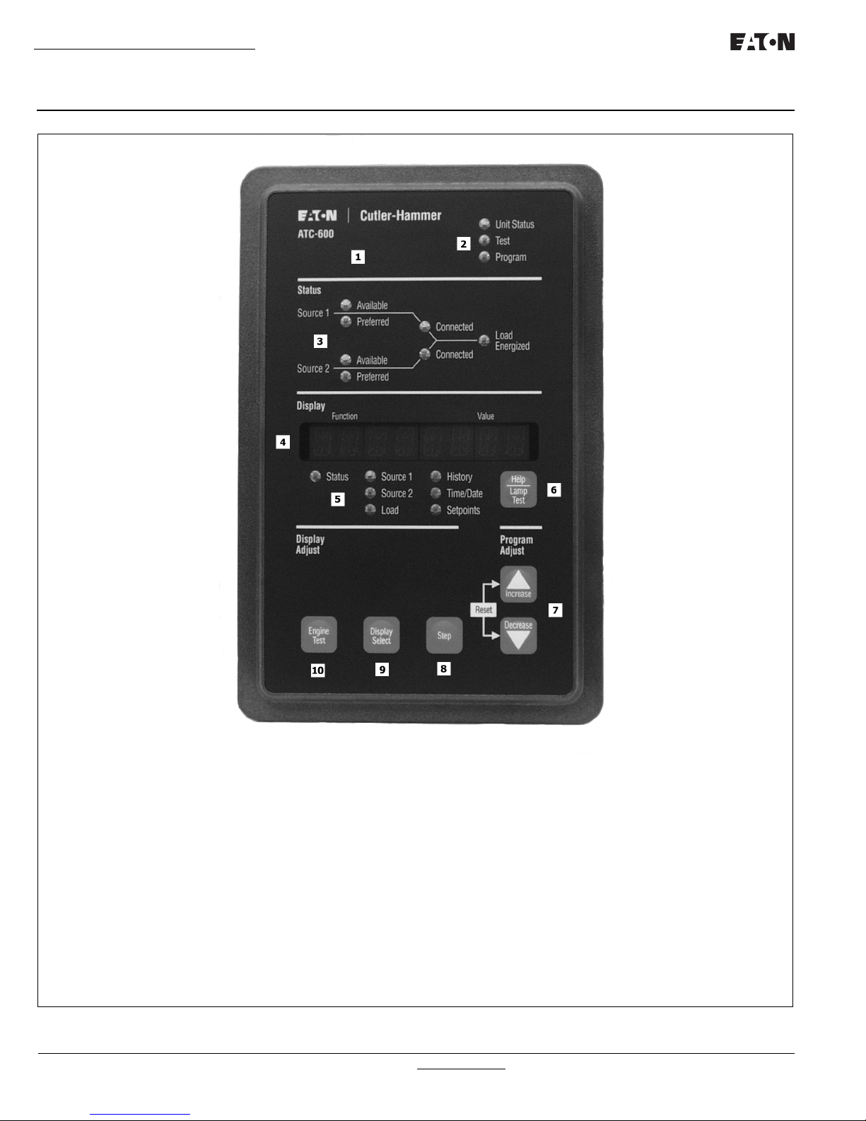
1. ATC-600 Faceplate (UV Resistant)
2. Operational Mode LEDs (highlighting ATC-600’s
present operational condition)
3. System Status Mimic Bus (easy to read and understand LED type)
4. Display Window (easy to read monitored parameters,
setpoints and messages)
5. Display LEDs (seven LEDs to identify the Display Window Information)
6. Help Pushbutton (provides English language help
information in any operational mode)
7. Increase/Decrease Pushbuttons (used individually,
pushbuttons move displayed information/setting up or
down through all possibilities – used simultaneously
while viewing historical logged values, values reset to
zero)
8. Step Pushbutton (used to step through different available information within the category being displayed)
9. Display Select Pushbutton (used to move the display
through the categories represented by the 7 LEDs
under the display)
10. Engine Test Pushbutton (pushed and released twice
to initiate a self test in Run or Program Modes
Page 8 Effective: March 2010
Instructions for Installation, Operation and Maintenance of the
Eaton ATC-600 Automatic Transfer Switch Controller
Figure 1. ATC-600 Operator Panel.
For more information visit: www.eaton.com IB ATS-1005
Instructions for Installation, Operation and Maintenance of the
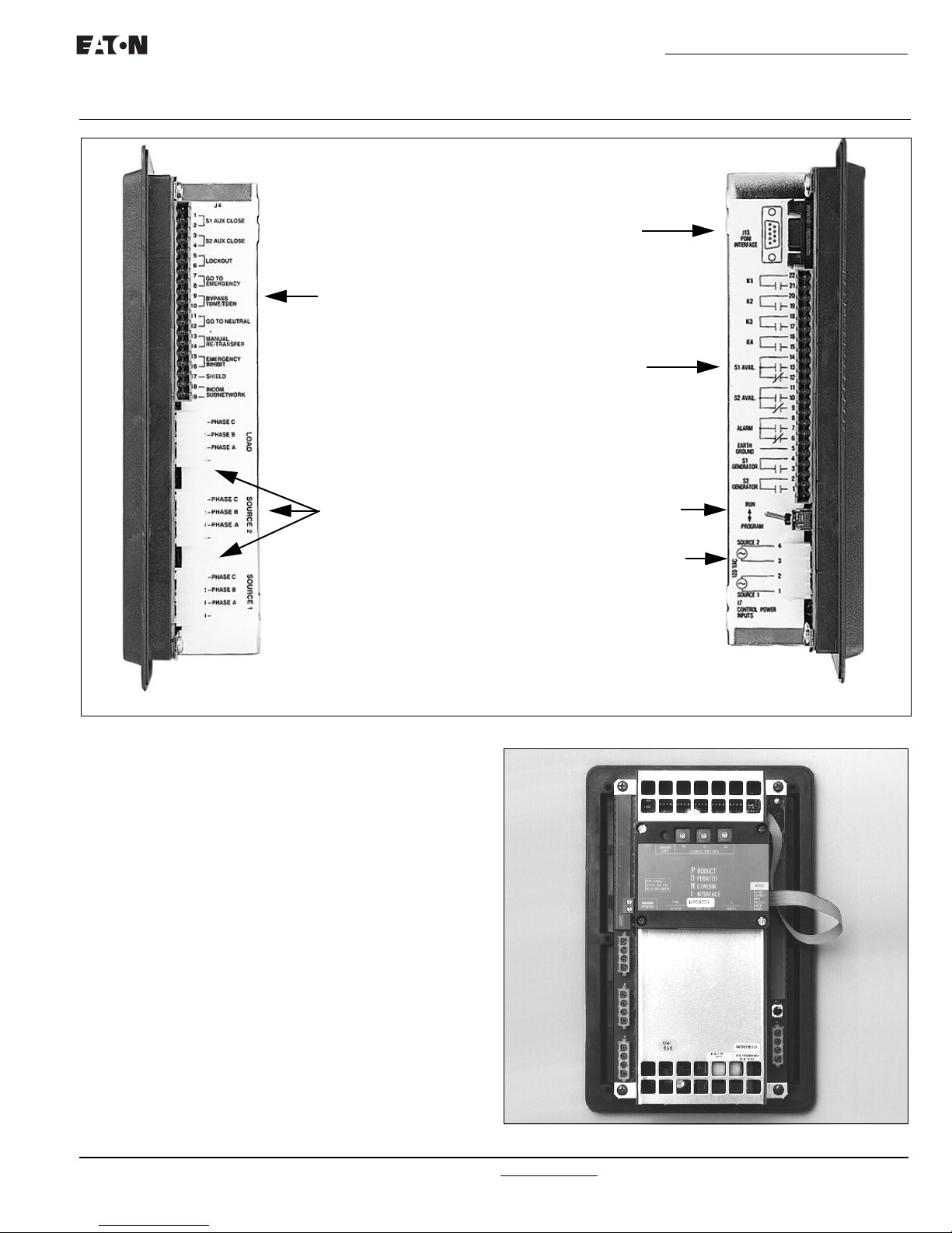
LEFT SIDE VIEW
Communication Module
Connector
J4 (Inputs) Terminal Block
(DC Wetted Contact)
J5 (Outputs) Terminal
Block (Dry Relay Contacts)
J1, J2, J3 Source/Load
Connectors
Program/Run
Toggle Switch
J7 Sources 1 and 2
Control Power
Connector
RIGHT SIDE VIEW
ATC-600 Controller - Breaker Type (CAT#8160A00G41)
Eaton ATC-600 Automatic Transfer Switch Controller
Instructional Booklet
Effective: March 2010 Page 9
Figure 2. ATC-600 (Left and Right Side Views).
2.4 External Hardware (Communication Module)
External hardware is viewed as any optional device mounted
directly to or remotely from the ATC-600, such as a communication module. Communications is made possible by mounting a
small, addressable communication module (PONI) to the back of
the ATC-600 (Figure 3) or in a remote location. Since the ATC600 is always supplied with a communications port, a PONI can
be easily retrofitted to the ATC-600 at any time. It is recom-
mended that the control power to the ATC-600 be removed prior
to connecting or disconnecting a PONI. When using the INCOM
PONI on the ATC-600, the PONI function switches should be set
to either of the Standard PONI modes (PONI 9600 Baud or PONI
1200 Baud). Refer to the instruction details supplied with the
PONI for details.
IB ATS-1005 For more information visit: www.eaton.com
Figure 3. Communication Module - PONI (mounted).

Instructional Booklet
Page 10 Effective: March 2010
2.5 Specification Summary
Refer to Table 1.
Table 1. ATC-600 Specifications
PARAMETER SPECIFICATION
Control Power: • 120Vac (50/60 Hz) (operating range 65 to 160 Vac)
Power Consumption: • 18VA
Environmental Conditions:
Operating Temperature • -20° to 70°C
Operating Humidity • up to 90% Relative Humidity (non-condensing)
Enclosure Compatibility: • NEMA 12 (standard mounting)
System Voltage Application: • 120 to 600 Vac (50/60 Hz) (single or three phase)
Voltage Measurements: • Source 1, Source 2 and Load (VAB, VBC, VCA for Three Phase System)
Voltage Measurement Range: • 0 to 700 Vac
Voltage Measurement Accuracy: • ±1% of Full Scale
Frequency Measurements: • Source 1 and Source 2
Frequency Measurement Range: • 40 to 80 Hz
Frequency Measurement Accuracy: • ±0.1 Hz
Undervoltage Dropout Range (Volts)
Breaker Switch Style ATS 50 to 97% of Nominal System Voltage
Undervoltage Pickup Range (Volts)
Breaker Switch Style ATS (Dropout +2%) to 99% of Nominal System Voltage
Overvoltage Dropout Range (Volts)
Breaker Switch Style ATS 105 to 120% Nominal System Voltage
Overvoltage Pickup (Volts)
Breaker Switch Style ATS 103% to (Dropout-2%) of Nominal System Voltage
Underfrequency Dropout (Hertz)
Breaker Switch Style ATS 90 to 97% of Nominal System Frequency
Underfrequency Pickup (Hertz)
Breaker Switch Style ATS (Dropout +1 Hz) to 99% of Nominal System Frequency
Overfrequency Dropout (Hertz)
Breaker Switch Style ATS 103 to 110% of Nominal System Frequency
Overfrequency Pickup (Hertz)
Breaker Switch Style ATS 101% to (Dropout -1 Hz) of Nominal System Frequency
Applicable Testing: • UL Recognized Component
• NEMA 4/4X (mounted with gasket between panel and device faceplate)
• NEMA 3R (outdoor)
• UV Resistant ATC-600 Faceplate
• Meets Seismic Requirements of Uniform and California Building Codes
(exceeding requirements of worst case Zone 4 levels)
• Complies with UL 991 environmental tests
• Complies with IEC 61000-4-2, 61000-4-3, 61000-4-4, and 61000-4-5
• Complies with CISPR 11, Class A
• Complies with FCC Part 15, Subpart B, Class A
Instructions for Installation, Operation and Maintenance of the
Eaton ATC-600 Automatic Transfer Switch Controller
For more information visit: www.eaton.com IB ATS-1005

Instructions for Installation, Operation and Maintenance of the
Eaton ATC-600 Automatic Transfer Switch Controller
Instructional Booklet
Effective: March 2010 Page 11
Section 3: Operator Panel
3.1 General
The operator panel, which is normally accessible from the outside
of a panel or door, provides a means for being alerted to specific
conditions, receiving functional help, programming, and parameter
monitoring/selection (Figure 1). For the purpose of familiarization,
the panel is divided into three sub-sections and discussed individually:
• LEDs
• Pushbuttons
• Display Window
NOTICE
WITH RESPECT TO THEIR USE IN THIS DOCUMENT AND AS THEY
RELATE TO AUTOMATIC TRANSFER SWITCH OPERATION, THE
WORDS “CYCLE” AND “EVENT” ARE DEFINED AS FOLLOWS:
CYCLE –A COMPLETE OPERATION FROM NORMAL TO EMERGENCY
TO NORMAL.
EVENT –A FAILURE RESULTING IN SOM E T YP E OF SWITC H AND/OR
SWITCH INTELLIGENCE ACTION.
NOTICE
REFER TO APPENDIX D FOR AN OVERALL VIEW OF ATC-600 OPERATIONS IN THE FORM OF A MENU TREE.
3.2 LEDS
LEDs are used to indicate the device’s mode of operation, the status
of the system, and the operations and/or conditions of displayed
functions. Three LEDs at the top of the ATC-600 provide a quick
snapshot of the unit’s status (Mode). Seven LEDs, just above the
display window, indicate which portions of the mimic bus are
active, and the actual status of both sources and load. The remaining seven LEDs, just below the display window, are lit to indicate
the identity of information being displayed.
Automatic Mode LED
This LED blinks green indicating that the ATC-600 is operating
and providing the transfer switch control function in keeping with
programmed setpoints. If the LED is not lit or is on continuously, a
problem may be indicated.
Test Mode LED
This LED is lit red upon entering the Test Mode. The Test Mode
can only be entered with the LEDs below the display window not
lit. When a test is initiated, the Status LED lights. Both LEDs will
turn off upon the successful completion of a test cycle.
Program Mode LED
This LED is lit red when the Run/Program switch on the rear of the
chassis is in the Program position. This condition permits programming of control setpoints. When the setpoints LED is lit indicating that existing setpoints can be changed, the Program Mode
LED blinks.
Source 1 Available - Status LED
This LED is lit amber if Source 1 meets the criteria for programmed Source 1 setpoints.
Source 1 Preferred - Status LED
This LED is lit red if Source 1 is the preferred source choice.
Source 1 Connected - Status LED
This LED is lit green if Source 1 is connected. This is accomplished by sensing the Source 1 breaker via the S1 closed auxiliary contact.
Source 2 Available - Status LED
This LED is lit amber if Source 2 meets the criteria for programmed Source 2 setpoints.
Source 2 Preferred - Status LED
This LED is lit red if Source 2 is the preferred source choice.
Source 2 Connected - Status LED
This LED is lit red if Source 2 is connected. This is accomplished
by sensing the Source 2 breaker via the S2 closed auxiliary contact.
Load Energized - Status LED
This LED is lit red if the load is connected to a source that is available.
CAUTION
LOAD ENERGIZE LED IS NOT A POSITIVE INDICATION THAT VOLTAGE IS NOT PRESENT ON THE LOAD TERMINALS.
Status - Display LED
This LED is lit red when action is occurring, such as a timer timing
down, and one of the other display categories has not been
selected. When the action is completed, the display goes blank
and the LED turns off. The Status position is the default position
of the display.
Source 1 - Display LED
This LED is lit green when displaying Source 1 voltage, frequency,
and status information. The LED also lights when displaying specific Source 1 setpoint information.
Source 2 - Display LED
This LED is lit red when displaying Source 2 voltage, frequency,
and status information. The LED also lights when displaying specific Source 2 setpoint information.
Load - Display LED
This LED is lit red when load voltage is being displayed.
History - Display LED
This LED is lit red when displaying historical information.
Time/Date - Display LED
This LED is lit red when displaying the time or date.
Setpoints - Display LED
This LED is lit red when displaying the programmed setpoints of
the ATC-600. When a specific displayed setpoint is associated
with one of the sources, the specific source LED will also be lit.
IB ATS-1005 For more information visit: www.eaton.com
 Loading...