

Eaton ATC-300 Instruction Booklet
O & M Manual for the EATON ATC-300
Breaker Based Transfer Switch
Instruction Booklet
Description Page
Introduction . . . . . . . . . . . . . . . . . . . . . . . . . . . . . . . 2
Receiving, Handling, and Storage . . . . . . . . . . . . . . . . . 6
Equipment Description. . . . . . . . . . . . . . . . . . . . . . . . . 7
Installation and Wiring . . . . . . . . . . . . . . . . . . . . . . . . 19
Operation . . . . . . . . . . . . . . . . . . . . . . . . . . . . . . . . . 29
Testing and Problem Solving . . . . . . . . . . . . . . . . . . . . 31
Adjustments . . . . . . . . . . . . . . . . . . . . . . . . . . . . . . . 33
Maintenance . . . . . . . . . . . . . . . . . . . . . . . . . . . . . . . 33
Renewal Parts Guide . . . . . . . . . . . . . . . . . . . . . . . . . 34
ATC-300 Controlled ATS Quick Start Instructions . . . . . 36
Appendix A: Pickup / Dropout Tables . . . . . . . . . . . . . . 47
IB01602008E For more information visit: www.eaton.com
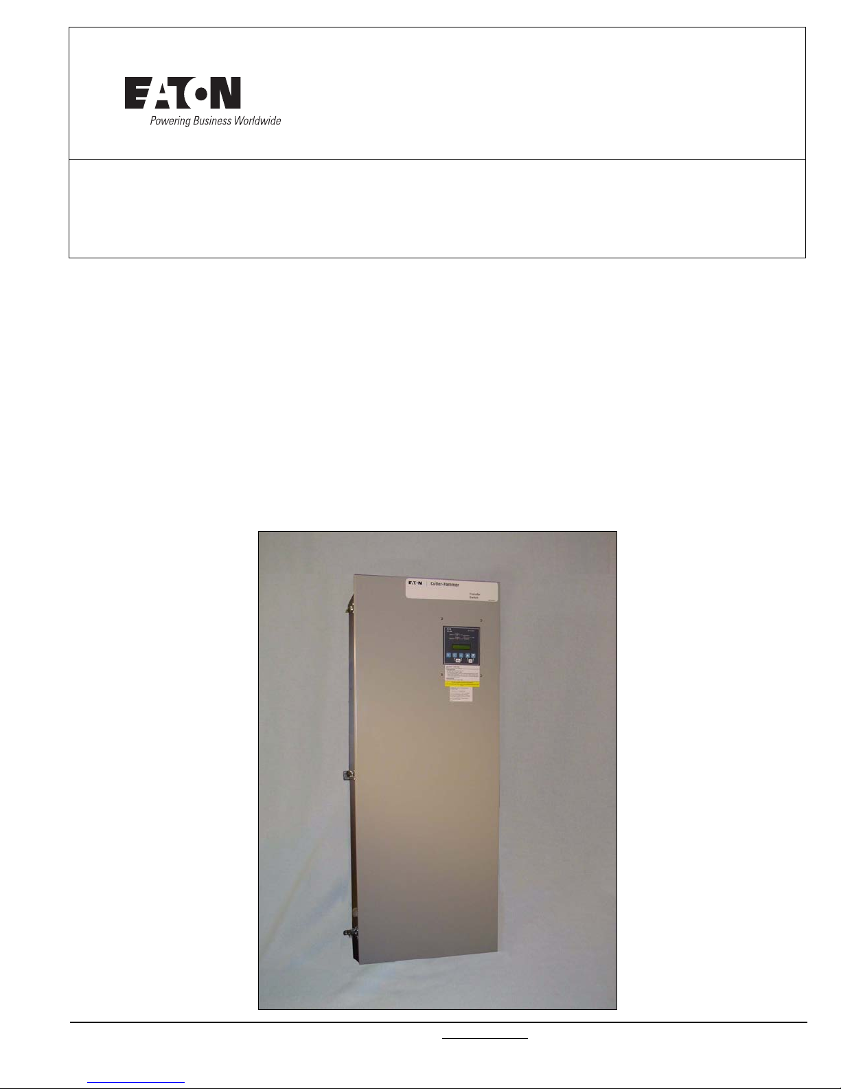
Instructional Booklet
E
Automatic T ransfer Switch
Cat No: ATV3KDA20225WRU 2/04
GO No: XYZ0123 1/1
Item 1
Poles: 2 Amps: 225 Volt: 240
Phase: 1 Hertz: 60 Wire: 3
Page 2 Effective: March 2014
ATC-300 Breaker Based Transfer Switch
Section 1: Introduction
WARNING
READ AND UNDERSTAND THE INSTRUCTIONS CONTAINED HEREINAFTER BEFORE ATTEMPTING TO UNPACK, ASSEMBLE, OPERATE, OR
MAINTAIN THIS EQUIPMENT.
HAZARDOUS VOLTAGES ARE PRESENT INSIDE TRANSFER SWITCH
ENCLOSURES THAT CAN CAUSE DEATH OR SEVERE PERSONAL
INJURY. FOLLOW PROPER INSTALLATION, OPERATION, AND MAINTENANCE PROCEDURES TO AVOID THESE VOLTAGES.
TRANSFER SWITCH EQUIPMENT COVERED BY THIS INSTRUCTION
BOOK IS DESIGNED AND TESTED TO OPERATE WITHIN ITS NAMEPLATE RATINGS. OPERATION OUTSIDE OF THESE RATINGS MAY
CAUSE THE EQUIPMENT TO FAIL RESULTING IN DEATH, SERIOUS
BODILY INJURY, AND/OR PROPERTY DAMAGE. ALL RESPONSIBLE
PERSONNEL SHOULD LOCATE THE DOOR MOUNTED EQUIPMENT
NAMEPLATE AND BE FAMILIAR WITH THE INFORMATION PROVIDED
ON THE NAMEPLATE. A TYPICAL EQUIPMENT NAMEPLATE IS
SHOWN IN FIGURE 1.
1.1 Preliminary Comments and Safety Precautions
This technical document is intended to cover most aspects associated with the installation, application, operation, and maintenance
of the Automatic Transfer Controller (ATC-300) Controlled ATS
with ratings from 30 through 1000 amperes (A). It is provided as
a guide for authorized and qualified personnel only. Please refer to
the specific WARNING and CAUTION in Section 1.1.2 before proceeding. If further information is required by the purchaser regarding a particular installation, application, or maintenance activity,
please contact an authorized Eaton sales representative or the
installing contractor.
1.1.1 Warranty and Liability Information
No warranties, expressed or implied, including warranties of fitness for a particular purpose of merchantability, or warranties arising from course of dealing or usage of trade, are made regarding
the information, recommendations and descriptions contained
herein. In no event will Eaton be responsible to the purchaser or
user in contract, in tort (including negligence), strict liability or
otherwise for any special, indirect, incidental or consequential
damage or loss whatsoever, including but not limited to damage or
loss of use of equipment, plant or power system, cost of capital,
loss of power, additional expenses in the use of existing power
facilities, or claims against the purchaser or user by its customers
resulting from the use of the information and descriptions contained herein.
1.1.2 Safety Precautions
All safety codes, safety standards, and/or regulations must be
strictly observed in the installation, operation, and maintenance of
this device.
Figure 1. Typical Automatic Transfer Switch (ATS) Equipment
Nameplate.
All possible contingencies that may arise during installation, operation, or maintenance, and all details and variations of this equipment do no purport to be covered by these instructions. If further
information is desired by the purchaser regarding a particular
installation, operation, or maintenance of particular equipment,
please contact an authorized Eaton Sales Representative or the
installing contractor.
WARNING
THE WARNINGS AND CAUTIONS INCLUDED AS PART OF THE PROCEDURAL STEPS IN THIS DOCUMENT ARE FOR PERSONNEL
SAFETY AND PROTECTION OF EQUIPMENT FROM DAMAGE. AN
EXAMPLE OF A TYPICAL WARNING LABEL HEADING IS SHOWN
ABOVE TO FAMILIARIZE PERSONNEL WITH THE STYLE OF PRESENTATION. THIS WILL HELP TO INSURE THAT PERSONNEL ARE ALERT
TO WARNINGS, WHICH APPEAR THROUGHOUT THE DOCUMENT.
IN ADDITION, WARNINGS AND CAUTIONS ARE ALL UPPER CASE
AND BOLDFACE.
CAUTION
COMPLETELY READ AND UNDERSTAND THE MATERIAL PRESENTED IN THIS DOCUMENT BEFORE ATTEMPTING INSTALLATION,
OPERATION, OR APPLICATION OF THE EQUIPMENT. IN ADDITION,
ONLY QUALIFIED PERSONS SHOULD BE PERMITTED TO PERFORM
ANY WORK ASSOCIATED WITH THIS EQUIPMENT. ANY WIRING
INSTRUCTIONS PRESENTED IN THIS DOCUMENT MUST BE FOLLOWED PRECISELY. FAILURE TO DO SO COULD CAUSE PERMANENT EQUIPMENT DAMAGE.
For more information visit: www.eaton.com IB01602008E
ATC-300 Breaker Based Transfer Switch
Source 1
Source 2
Load
Instructional Booklet
Effective: March 2014 Page 3
1.2 General Information
Transfer switches are used to protect critical electrical loads
against loss of power. The load’s Source 1 power source is
backed up by a Source 2 power source. A transfer switch is connected to both the Source 1 and Source 2 power sources and supplies the load with power from one of the two sources. In the
event that power is lost from Source 1, the transfer switch transfers the load to the Source 2 power source. This transfer can be
automatic or manual, depending upon the type of transfer switch
equipment being used. Once Source 1 power is restored, the load
is automatically or manually transferred back to the Source 1
power source, again depending upon the type of transfer equipment being used (Figure 2).
source until the Source 2 power source does appear. Conversely,
if connected to the Source 2 power source and the Source 2
power source fails while the Source 1 power source is still
unavailable, the ATS remains connected to the Source 2 power
source.
ATSs automatically perform the transfer function, and include
three basic elements:
1. Main contacts to connect and disconnect the load to and from
the power source.
2. A mechanism to transfer the main contacts from source to
source.
3. Intelligence/supervisory circuits to constantly monitor the condition of the power sources and thus provide the intelligence
necessary for the switch and related circuit operation.
1.2.1 Design Configuration
The Eaton ATS is a rugged, compact design that uses molded
case switches and/or circuit breakers to transfer essential loads
from one power source to another (Figures 3 [225-1200 A] and 4
[30-150 A]). Molded case switches are mechanically and electri-
cally interlocked to prevent both switching devices from being
closed at the same time.
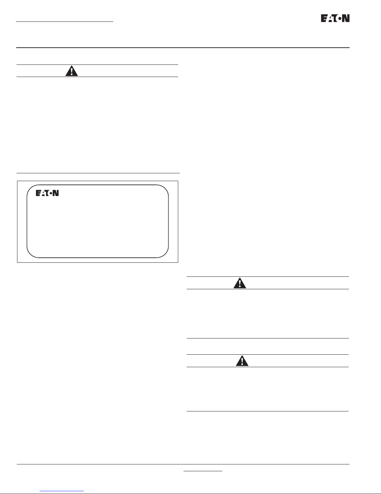
Figure 2. Typical Load Transfer Switch (Circuit Breaker Type)
Schematic.
In ATS equipment, the switch’s intelligence system initiates the
transfer when the Source 1 power fails, falls below, or rises above
a preset voltage. If the Source 2 power source is a standby generator, the ATS initiates generator startup and transfers to the
Source 2 power source when sufficient generator voltage is available. When Source 1 power is restored, the ATS automatically
transfers back and initiates generator shutdown. In the event the
Source 1 power source fails and the Source 2 power source does
not appear, the ATS remains connected to the Source 1 power
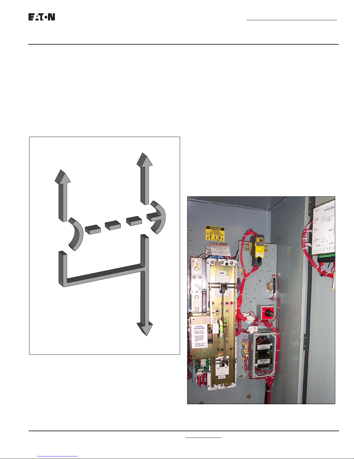
Figure 3. Typical Power Panel for 225-1200 A Models (Deadfront
Covers Removed).
IB01602008E For more information visit: www.eaton.com
Instructional Booklet
Page 4 Effective: March 2014
Figure 4. Typical Power Panel for 30-150 A Models (Deadfront
Cover Installed).
Molded case switches and the associated transfer mechanisms
are mounted vertically to save space in the assembly. The compact, vertical configuration uses a positive, metallic transfer and
interlocking system between the molded case switches.
The Eaton ATS was designed with easy installation and simplified
maintenance in mind. Three main panels compromise the transfer
switch design:
1. Power panel;
2. Voltage selection and transformer panel (if required); and
3. Microprocessor-based logic panel.
ATC-300 Breaker Based Transfer Switch
Figure 5. Vertical Design Transfer Switch with the Deadfront
Cover in Place Over the Power Panel (225-1200 A).
Each panel is independently mounted with interconnecting wiring
terminated at the connector receptacles on the ATC-300 Controller. Door or individual panel removal is achieved without disturbing critical connections by removing the connectors from the
receptacles and cutting the wire ties that secure the wires to the
door.
Mounting the enclosure is simple using top and bottom mounting
flanges with elongated (teardrop) mounting holes. These mounting holes, along with power panel positioning bolts and pre-tapped
inserts, insure proper power panel mounting after the initial enclosure installation or when switching from top to bottom or bottom
to top entry. Refer to Section 4 for specific mounting and modification details.
Table 1. Withstand Ratings
UL 1008 WITHSTAND AND CLOSE-ON RATINGS (kA)
UL 1008 3-Cycle
Switch
Rating
Amperes
30-100
150
150-225
225
300
400
600
800
1000
4 pole 480 Vac are rated 35 kA
“Any Breaker” Rating
240 Vac 480 Vac 600 Vac
100
100
100
100
100
100
100
65
65
65
65
65 (240 Vac)
65
65
65
65
50
50
25
25
25
25
25
25
25
25
25
Rating When Used
With Upstream Fuse
Maximum
Fuse Rating
200
400
400
400
400
600
1200
1600
1600
Fuse
Type 600 Vac
J, T
J, T
J, T
J, T
J, T
J, T
J, T
L
L
200
200
200
200
200
200
200
200
200
For more information visit: www.eaton.com IB01602008E

ATC-300 Breaker Based Transfer Switch
Instructional Booklet
Effective: March 2014 Page 5
1.3 ATS Catalog Number Identification
Transfer switch equipment catalog numbers provide a significant
amount of relevant information that pertains to a particular piece
of equipment. The Catalog Number Identification Table (Table 2)
provides the required interpretation information. An example is
offered here to initially simplify the process.
Example: Catalog Number (circled numbers correspond to position
The catalog number ATV3KDA20225WRU describes an ATS with
the switching devices mounted vertically in the enclosure. The
intelligence represented by the control panel is ATC-300 logic.
The Eaton Series C Type HKD is used as the switching device and
is in the form of a 2-pole molded case switch on each source. The
continuous current rating of this equipment is 225 A and applicable at 240 Vac, 60 Hz. The transfer switch equipment is enclosed
in a NEMA 3R enclosure and is listed for UL applications.
headings in Table 2):
1 to 2 3 4 5 to 6 7 8 9 to 12 13 14 15
AT V 3 KD A 2 0225 W R U
Table 2. Transfer Switch Catalog Number Explanation
POSITIONS 1 TO 2 POSITION 3 POSITION 4 POSITIONS 5 TO 6
BASIC
DEVICE
Automatic Transfer Switch AT Vertical V1
POSITION 7 POSITION 8 POSITIONS 9 TO 12 POSITION 13 POSITION 14 POSITION 15
SWITCHING DEVICE
ARRANGEMENT
NUMBER
OF POLES
SWITCHING DEVICE
ORIENTATION
Horizontal H
2
AMPERE
RATING
CONTROL
PANEL
ATC-300
Controller
VOLTAGE/
FREQUENCY ENCLOSURE LISTING
3 HFD
HKD
HLD
HMDL
NB
HND
Eaton Series C
Eaton Series C
Eaton Series C
Eaton
Eaton
3
Eaton Series C
SWITCHING
DEVICE
FD
KD
LD
MD
NB
ND
Fixed Mount Molded Case A Two 2 30 A – 0030 600 Vac/60 Hz E Type 12 J *UL/CSA Listing U
Switches Both Power Sources Three 3 70 A – 0070 480 Vac/60 Hz X Type 3R R No Listing X
Fixed Mount Molded Case B Four 4 100 A – 0100 240 Vac/60 Hz W Open K
Circuit Breakers Both Power Sources 150 A – 0150 208 Vac/60 Hz B
Fixed Mount Molded Case C 225 A – 0225 120 Vac/60 Hz A
Circuit Breaker Source 1 Power Source, 300 A – 0300 220 Vac/50 or 60 Hz G
Molded Case Switch Source 2 400 A – 0400 600 Vac/50 Hz K
Power Source 600 A – 0600 415 Vac/50 Hz O
Fixed Mount Molded Case D 800 A – 0800 401 Vac/50 Hz N
Switch Source 1 Power Source, 1000 A – 1000 380 Vac/50 Hz H
Molded Case Circuit Breaker 1200 A – 1200 365 Vac/50 Hz Z
Source 2 Power Source 230 Vac/50 Hz M
Notes: 1 Vertical orientation (225-1200 A)
2 Horizontal orientation (30-150 A)
3 Consult factory for availability.
*CSA will only be applied to molded case switches, both
power sources.
1.4 Environmental Conditions
1.4.1 Seismic
With proper installation, and by including the appropriate optional
feature that includes specially designed cleats (optional feature
#42), the ATSs have a seismic capability which exceeds the worst
case Zone 4 required levels, per both the Uniform Building Code
and the California Building Code.
1.4.2 Operational Conditions
Normally, an ATS is applied indoors in an electrical equipment
room. In the appropriate enclosure, it can be used for outdoor
applications were the equipment is subject to falling rain, freezing
temperatures, and no greater than 90% humidity (non-condensing). The ambient temperature range for operation is between -20
and 70°C (-4 to 158°F).
IB01602008E For more information visit: www.eaton.com

Instructional Booklet
Page 6 Effective: March 2014
ATC-300 Breaker Based Transfer Switch
1.5 Glossary
With respect to their use within this document and as they
relate to transfer switch and controller operation, the following terminology is defined.
Available
A source is defined as “available” when it is within its undervoltage/overvoltage/ underfrequency/overfrequency (if applicable) setpoint ranges for the nominal voltage and frequency
setting.
Connected
Connected is defined as when the input is shorted by an
external contact or connection.
Failed or Fails
A source is defined as “failed” when it is outside of the applicable voltage and frequency setpoint ranges for the nominal
voltage and frequency setting for a time exceeding 0.5 seconds after the time delay emergency fail (TDEF) time delays
expires.
Failsafe
Failsafe is a feature that prevents disconnection from the only
available power source and also forces a transfer or re-transfer operation to the only available power source.
Re-Transfer
Re-transfer is defined as a change of the load connection
from the Source 2 to the Source 1.
Source 1
Source 1 is the primary source (normal source, normal power
source, or normal).
Source 2
Source 2 is the secondary source (emergency source, emergency power source, emergency, standby, or backup source).
Source 1: Failed or Fails
Source 1 is defined as “failed” when it is outside of its undervoltage/overvoltage/ underfrequency/overfrequency (if applicable) setpoint ranges for the nominal voltage and frequency
setting.
Source 2: Failed or Fails
Source 2 is defined as “failed” when it is outside of its undervoltage/overvoltage/ underfrequency/overfrequency (if applicable) setpoint ranges for the nominal voltage and frequency
setting for a time exceeding 0.5 seconds after the Time Delay
Emergency Fail (TDEF) time delay expires.
Transfer
Transfer is defined as a change of the load connection from
the Source 1 to the Source 2 power source, except when
specifically used as “Transfer to Neutral”.
Transfer to Neutral
Transfer to Neutral is defined as when the load circuits are
disconnect from both the Source 1 and Source 2 power
sources.
Unconnected
Unconnected is defined as when the input is not shorted by
an external contact or connection.
Section 2: Receiving, Handling, and
Storage
2.1 Receiving
Every effort is made to ensure that the ATS equipment
arrives at its destination undamaged and ready for installation. Packing is designed to protect internal components as
well as the enclosure. Care should be exercised, however, to
protect the equipment from impact at all times. Do not
remove the protective packaging until the equipment is ready
for installation.
When the ATS equipment reaches its destination, the customer should inspect the shipping container for any obvious
signs of rough handling and/or external damage that occurred
during transportation. Record any external and internal damage for reporting to the transportation carrier and Eaton, once
a thorough inspection is complete. All claims should be as
specific as possible and include the Shop Order and General
Order numbers.
A shipping label affixed to the shipping container includes a
variety of equipment and customer information, such as General Order Number and Customer Number. Make certain that
this information matches other shipping paper information.
Each transfer switch enclosure is bolted through its top and
bottom mounting flanges to a rigid wooden pallet. The pallet
is open at two ends for movement by a forklift. Heavy-duty
cardboard sides surround the enclosure and are further supported with reinforced cardboard corner posts. An egg crate
design cardboard protector covers the entire top of the enclosure with additional cardboard protectors over the indicating
light panel and operating handle. A heavy-duty cardboard lid
covers the entire opening. The shipment is secured and further protected with shrink-wrap. Do not remove or discard
the packing material until the equipment is ready for installation.
Once the top packaging is removed from the shipment, the
enclosure door can be opened. A plastic bag of documents
will be found in the enclosure, usually attached to the inside
of the door. Important documents, such as test reports, wiring diagrams, and appropriate instruction leaflets, are
enclosed within the bag and should be filed in a safe place.
2.2 Handling
As previously mentioned, ATS equipment is packaged for
forklift movement. Protect the equipment from impact at all
times and DO NOT double stack.
Once the equipment is at the installation location and ready
to be installed, packaging material can be removed and discarded. Once the enclosure is unbolted from the wooden pallet, it can be hand moved to its installation position. Be
careful not to damage the top or bottom enclosure mounting
flanges. Refer to Section 4 of this manual for specific installation instructions.
For more information visit: www.eaton.com IB01602008E
ATC-300 Breaker Based Transfer Switch
POWER PANEL
LOGIC
PANEL
VOLTAGE SELECTION
AND TRANSFORMER
PANEL
Instructional Booklet
Effective: March 2014 Page 7
2.3 Storage
Although well packaged, this equipment is not suitable for outdoor
storage. The equipment warranty will not be applicable if there is
evidence of outdoor storage. If the equipment is to be stored
indoors for any period of time, it should be stored with its protective packaging material in place. Protect the equipment at all
times from excessive moisture, construction dirt, corrosive conditions, and other contaminants.
It is strongly suggested that the package-protected equipment be
stored in a climate-controlled environment with temperatures from
-30 to 85°C (-22 to 185°F) and with a relative humidity of 80%
or less. DO NOT, under any circumstance, stack other equipment
on top of a transfer switch equipment enclosure, whether packaged or not.
Section 3: Equipment Description
3.1 General
The ATS consists of three basic panels:
1. The power panel;
2. The voltage selection and transformer panel; and
3. The microprocessor-based logic panel.
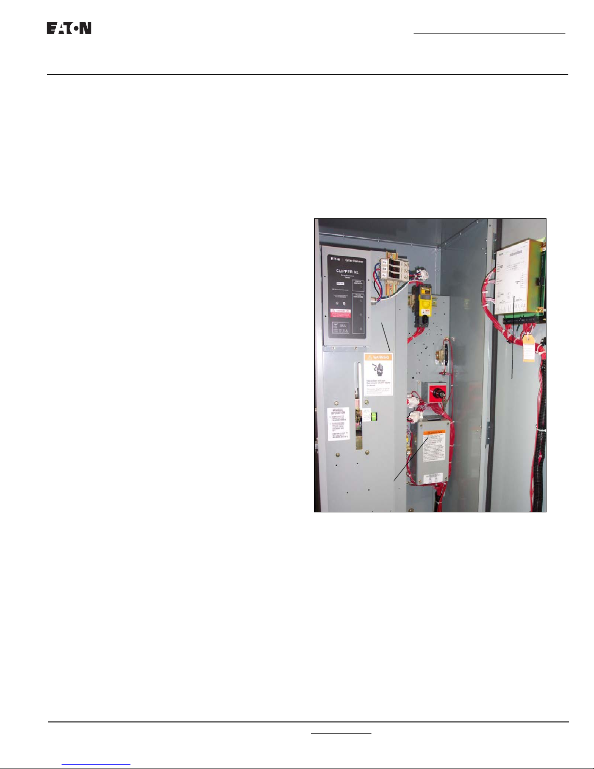
These panels are interconnected via connector plugs and mounted
in an enclosure (Figure 6).
IB01602008E For more information visit: www.eaton.com
Figure 6. Three Basic Panels of the ATS (225-1200 A).
3.2 Power Panel
The power panel is used for making load, power, and neutral connections. The main contacts and the transfer mechanism are all
on one steel frame (Figures 7 and 8).
Instructional Booklet
Page 8 Effective: March 2014
ATC-300 Breaker Based Transfer Switch
3.2.1 Steel Base Plate
The steel base plate design (225-1200 A models only) permits the
power panel to be moved vertically within the enclosure to accommodate top or bottom cable entry. Elongated holes on either side
of the base plate ensure proper positioning. The bottom set of
elongated holes positions the power panel higher in the enclosure,
thus permitting bottom cable entry. The top set of elongated
holes positions the power panel lower in the enclosure for top
cable entry. Section 4 discusses equipment mounting and load
lug location in detail.
3.2.2 Main Contacts
This ATS incorporates Eaton-type molded case switches. The
main contacts connect and disconnect the load to and from the
different power sources. High-withstand molded case switches
are the main contacts for the Source 1 and Source 2 power
sources in standard switch ATSs (Figure 9 and Section 3.7).
These continuous duty transfer switches are rated for all classes
of loads, open or enclosed.
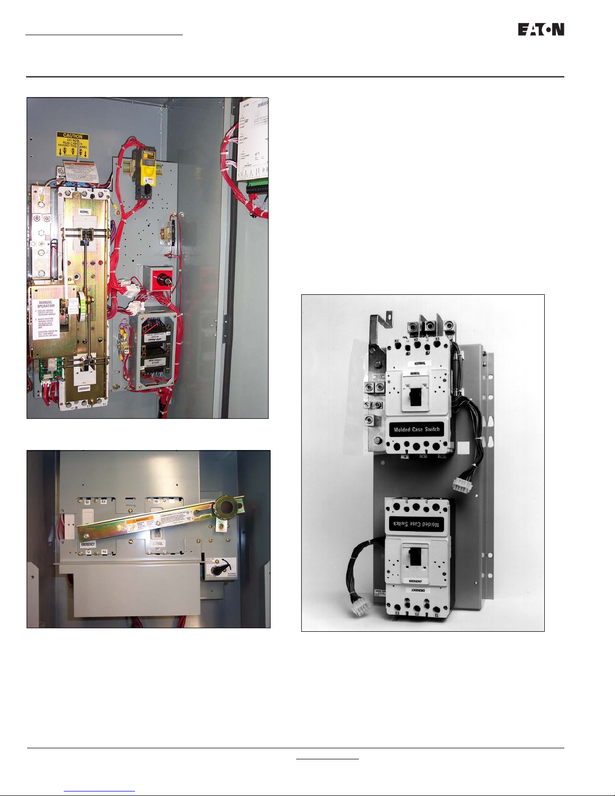
Figure 7. Typical Power Panel for 225-1200 A Models.
Figure 8. Typical Power Panel for 30-150 A Models.
Figure 9. Mounted Molded Case Switches with the Transfer
Mechanism Removed for Clarity (225-1200 A Models).
In addition, they have high dielectric strength, heavy-duty switching, high-withstand capabilities, and high interruption capacity.
The switching devices are mechanically and electrically interlocked to prevent the two sets of main contacts from being closed
simultaneously. The load side contacts of each switching device
are joined with a bus bar assembly to form a common load terminal location, either top or bottom (Figures 10 and 11).
For more information visit: www.eaton.com IB01602008E
ATC-300 Breaker Based Transfer Switch
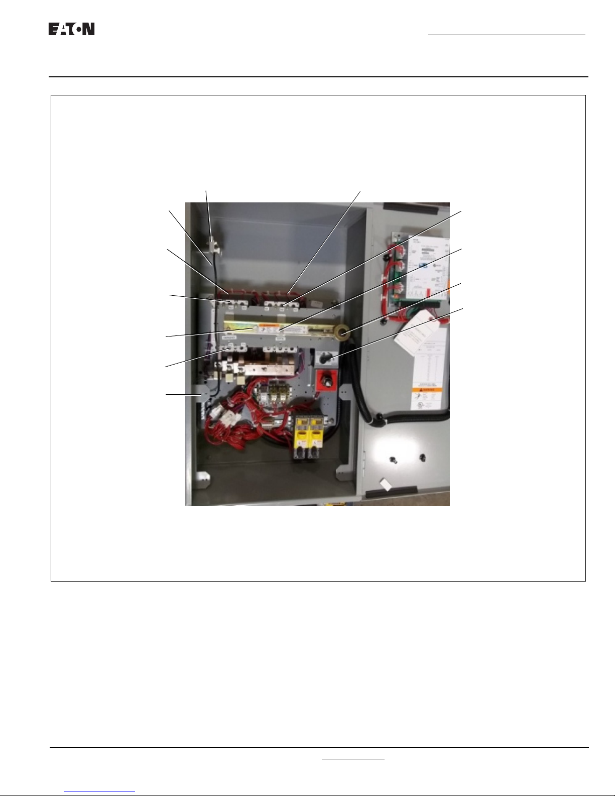
NORMAL POWER
SOURCE SWITCHING
DEVICE
NORMAL LINE
CONNECTIONS
MANUAL OPERATOR
KNOB
BRAKE RELEASE
LEVER
NEUTRAL BOND
(FOR SERVICE
NEUTRAL
ASSEMBLY
GROUND
CONNECTIONS
TRANFER
MECHANISM
EMERGENCY LINE
CONNECTIONS
EMERGENCY POWER
SOURCE SWITCHING
DEVICE
PIVOT
BOLT
LOAD
CONNECTIONS
ENTRANCE)
Instructional Booklet
Effective: March 2014 Page 9
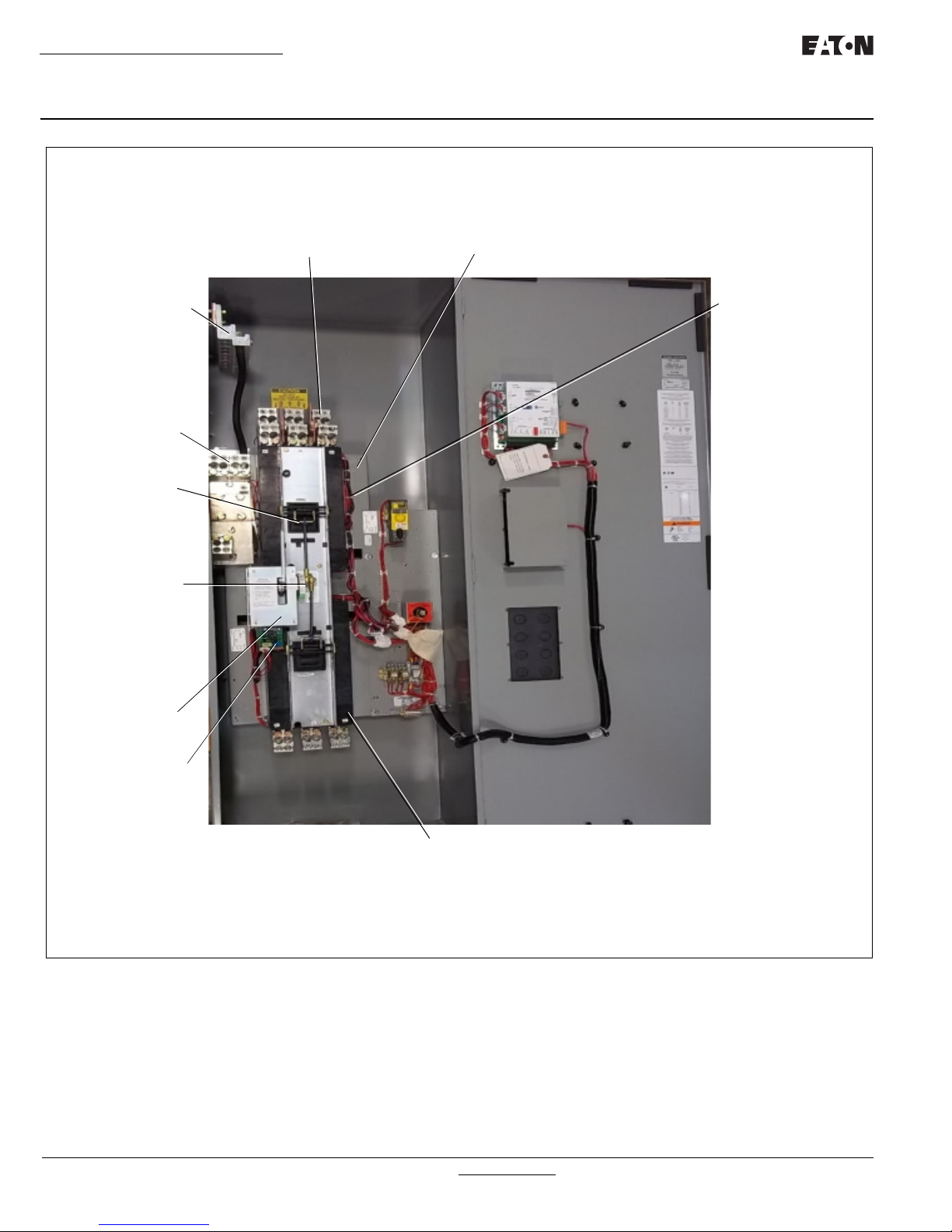
Figure 10. Typical (30-150 A) Horizontal Design Transfer Switch Equipment (Door Open).
IB01602008E For more information visit: www.eaton.com
Instructional Booklet
NORMAL POWER
SOURCE MOLDED
CASE SWITCH
GROUND
CONNECTIONS
MANUAL
OPERATING
HANDLE
INDICATOR
WHEEL
TRANSFER
MECHANISM
MOTOR BRAKE
BOARD
EMERGENCY
POWER SOURCE
MOLDED CASE
SWITCH
NEUTRAL
CONNECTIONS
LOAD LUGS (TOP ENTRY)
POWER PANEL
Page 10 Effective: March 2014
ATC-300 Breaker Based Transfer Switch
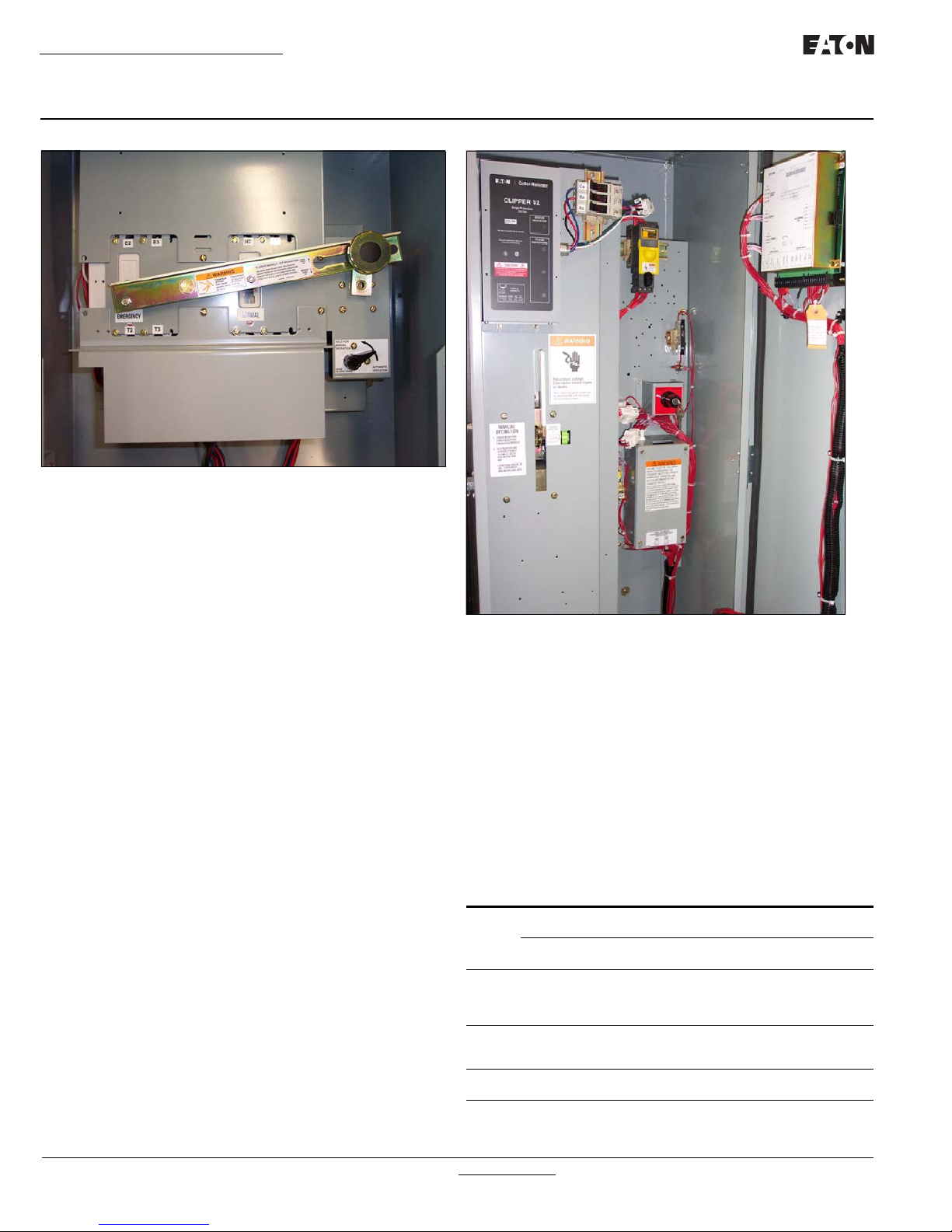
Figure 11.Typical (225-1200 A) Vertical Design Transfer Switch Equipment (Door Open and Deadfront Cover Removed).
3.2.3 Transfer Mechanism (225-1200 A)
The transfer mechanism transfers between power sources
through a motor-driven, ratchet-type operation. A rotational
motion is created on an indicator wheel by the ratchet’s operation. The indicator wheel is attached to rigid shafts that convert
the rotary motion into vertical linear motion. Opening and closing
the switching devices is accomplished as a result of this vertical
linear motion. The transfer mechanism is mounted in front of the
molded case switches (Figure 6).
For more information visit: www.eaton.com IB01602008E

ATC-300 Breaker Based Transfer Switch
A solid steel shield (Deadfront Cover) attached to the ratchet
assembly permits viewing of the rotary switch position indicator
while restricting access to other parts of the power panel (Figure
12).
Instructional Booklet
Effective: March 2014 Page 11
Figure 12.Vertical Design ATS Equipment with Deadfront Cover in
Place Over the Power Panel (225-1200 A)
3.2.4 Transfer Mechanism (30-150 A)
This mechanism transfers between power sources using a motordriven arm that connects to a lever that operates both the Source
1 and Source 2 switches (Figure 8).
3.3 Voltage Selection
3.3.1 North American Voltage Selection (120, 208, 240,
480, and 600 V, - 60 Hz)
The North American market voltage selection panel consists of
multi-tap transformers, contained in a steel case mounted in the
enclosure (Figure 13). The cover has “teardrop” holes for the
screws to allow easy access to the transformers. The voltage is
selected by simply removing the wires from the default primary
taps of both transformers and installing them on the primary taps
for the desired voltage. Taps are provided for 120 to 600 Vac to
satisfy any required North American market application voltage.
The factory default position is 600 Vac.
CAUTION
WHEN CHANGING THE SELECTED VOLTAGE, THE POWER MUST BE
REMOVED FROM THE ATS AND THE WIRES MUST BE MOVED ON THE
TAPS OF BOTH TRANSFORMERS.
Figure 13.North American Market Voltage Selection Terminals
(Shown Connected to the 120 Vac Taps).
IB01602008E For more information visit: www.eaton.com
Instructional Booklet
Page 12 Effective: March 2014
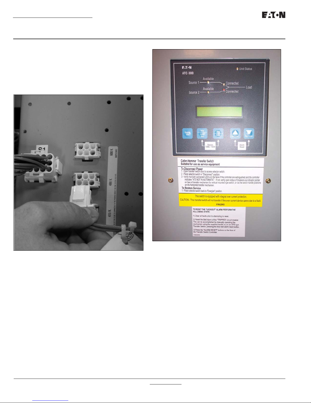
3.3.2 International Voltage Selection (208, 220, 240,
380, 415, and 600 V - 50-60 Hz)
The International market voltage selection panel is a multi-tap,
enclosed transformer mounted in the enclosure (Figure 14).
Seven front accessible voltages taps from 208 to 600 Vac satisfy
any required International market application voltage. A quickchange capability from one voltage to another is provided by a
small disconnect plug. The factory default position is 600 VAC.
ATC-300 Breaker Based Transfer Switch
Figure 14.International Market Vertical Design Voltage Selection
Panel with Voltage Being Selected.
3.4 ATC-300 Logic Panel
The ATC-300 is a microprocessor-based transfer switch logic control package. The hardware and software of the controller contain
the intelligence/supervisory circuits that constantly monitor the
condition of the power sources. It provides the intelligence necessary for the operation of the ATS (Figure 15).
For more information visit: www.eaton.com IB01602008E
Figure 15.ATC-300 Logic Control Panel.
The ATC-300 controller has an operating temperature of
-20 to 70°C (-4 to 158°F).
The controller circuit board is protected by an insulating conformal
coating.
The specifications, under normal operating conditions, are as follows:
• Tolerance for voltage sensing function: ±1% of setting
• Tolerance for frequency sensing function: ±0.3 Hz of setting

ATC-300 Breaker Based Transfer Switch
Instructional Booklet
Effective: March 2014 Page 13
3.5 Features
A variety of standard and optional features are available for Eaton
ATSs. All features or combinations of features may not be avail-
able on specific ATSs. All features and/or accessories are Underwriters Laboratories (UL) listed unless noted.
3.5.1 Standard Features
The following is a list of the standard features for the ATC-300
Controlled ATS.
1. Time Delay Normal to Emergency (TDNE)
This feature provides a time delay when transferring from the
Source 1 to the Source 2 power source. Timing begins
when Source 2 becomes available. It permits controlled
transfer of the load circuit to Source 2.
Adjustable 0 - 1800 Seconds
2. Time Delay on Engine Starting (TDES)
This feature provides a time delay of the signal to initiate the
engine/generator start cycle in order to override momentary
power outages or voltage fluctuations of Source 1.
Adjustable 0 - 120 Seconds
3. Time Delay Emergency to Normal (TDEN)
This feature provides a time delay of the re-transfer operation to permit stabilization of Source 1. Timing begins when
Source 1 becomes available. If Source 2 fails during timing,
then re-transfer is immediate overriding the time delay.
Adjustable 0 - 1800 Seconds
4. Time Delay for Engine Cool-down (TDEC)
This feature provides a time delay of the signal to initiate the
engine/generator stop cycle after the re-transfer operation.
This allows the engine/generator to cool down by running
unloaded. Timing begins on completion of the re-transfer
cycle.
Adjustable 0 - 1800 Seconds
5, Source 2 Monitoring and Protection
This feature provides monitoring and protection based on the
Source 2 voltage and/or frequency setpoints. All feature 5
functions are “failsafe” operations.
5B. 1-Phase Undervoltage and Underfrequency Protection
Adjustable Undervoltage:
Dropout: 50 - 97% of nominal
Pickup: (Dropout +2%) to 99% of nominal
Adjustable Underfrequency:
Dropout: 90 - 97% of nominal
Pickup: (Dropout +1Hz) to 99% of nominal
5C. 1-Phase Overvoltage/Overfrequency
Adjustable Overvoltage:
Dropout: 105 - 120% of nominal
Pickup: 103% to (Dropout –2%) of nominal
Adjustable Overfrequency:
Dropout: 103 - 110% of nominal
Pickup:101% to (Dropout -1Hz) of nominal
5D. 1-Phase Undervoltage
Adjustable Undervoltage:
Dropout: 50 - 97% of nominal
Pickup: (Dropout +2%) to 99% of nominal
5E. 1-Phase Overvoltage
Adjustable Overvoltage:
Dropout: 105 - 120% of nominal
Pickup: 103% of to (Dropout –2%) of nominal
5F. 3-Phase Undervoltage
Adjustable Undervoltage:
Dropout: 50 - 97% of nominal
Pickup: (Dropout +2%) to 99% of nominal
5G. 3-Phase Overvoltage
Adjustable Overvoltage:
Dropout: 105 - 120% of nominal
Pickup: 103% to (Dropout –2%) of nominal
5H. Phase Reversal
For a 3-phase wye source, this feature monitors the phase
sequence of the sources. If a source does not have the same
ABC or CBA sequence as the setpoint value, that source will
be considered “Unavailable.
For a 3-phase delta source, this feature should be turned off
via the PHASE REV setpoint.
5J. 3-Phase Undervoltage and Underfrequency Protection
Adjustable Undervoltage:
Dropout: 50 - 97% of nominal
Pickup: (Dropout +2%) to 99% of nominal
Adjustable Underfrequency:
Dropout : 90 - 97% of nominal
Pickup: (Dropout +1Hz) to 99% of nominal
IB01602008E For more information visit: www.eaton.com

Instructional Booklet
Page 14 Effective: March 2014
ATC-300 Breaker Based Transfer Switch
5K. 3-Phase Overvoltage/Overfrequency
Adjustable Overvoltage:
Dropout: 105 - 120% of nominal
Pickup: 103% to (Dropout –2%) of nominal
Adjustable Overfrequency:
Dropout: 103 - 110% of nominal
Pickup: 101% to (Dropout -1Hz) of nominal
5L. Source 2 3-Phase Voltage Unbalance
For a 3-phase wye source, this feature monitors phase voltage ratios. Voltage unbalance (%) is calculated as the difference between the maximum and minimum phase voltage,
divided by the minimum phase voltage. User-selectable setpoints are available for dropout and pickup unbalance settings (minimum 2% differential). Dropout is adjustable from
5 to 20%. Pickup is adjustable from 3 to (Dropout –2%). A
setpoint for user-selectable time delay from 10 to 30 seconds is provided. The factory default setpoints are: 5%
dropout, 3% pickup, and 30 seconds time delay. A userselectable setpoint for enable and disable is also provided.
When an unbalance condition is detected on Source 2, the
Unbalance Timer (TD UNBAL) starts timing. After TD
UNBAL times out, Source 2 is declared “failed”.
For a 3-phase delta source, this feature should be turned off
via the VOLT UNBAL setpoint.
6. Test Operators
Eaton ATSs are provided with a Test Pushbutton that simulates a loss of the Source 1 power source as standard (Feature 6B). All programmed time delays (TDNE, TDEN, etc.)
will be performed as part of the Test. Engine run time of the
Test is equal to the Plant Exerciser (Feature 23) programmed
setpoint. All Tests are Failsafe protected.
6B. Test Pushbutton
Programmable Setpoints include:
1. Load or No Load Testing, or Disabled
2. Engine run time equal to the plant exerciser (Feature
23) setting
7. Time Delay Emergency Fail (TDEF)
This feature provides a time delay that prevents a connected
Source 2 power source from being declared “Failed” in order
to override momentary generator fluctuations. If the Source
2 power source remains in the failed state then, 0.5 seconds
after the TDEF timer expires, the transfer switch will proceed
with the programmed sequence for retransfer. This time
delay is only implemented when the Source 2 power source
is a generator.
Adjustable 0 - 6 Seconds
8. Time Delay Bypass Pushbutton
This feature provides a way (by pushing the Help and Step
pushbutton simultaneously) to bypass the TDNE (Feature 1)
and/or TDEN (Feature 2) time delays. The Time Delay
Bypass function, when activated by pushing the Help and
Step pushbutton simultaneously, will reduce any or all of the
programmed time delay to zero.
8C. Bypass TDEN
This feature provides one set of pushbuttons to bypass the
TDEN time delay.
8D. Bypass TDNE
This feature provides one set of pushbuttons to bypass the
TDNE time delay.
12. Power Source Annunciation
This feature provides LEDs to give switch position and power
source availability indications.
Switch Position
Provides LEDs to indicate the switch position.
12C. Source 1 - Source Connected
This feature provides a green LED that, when lit, indicates
the load is connected to Source 1.
12D. Source 2 - Source Connected
This feature provides a red LED that, when lit, indicates the
load is connected to Source 2.
Power Source Availability
Provides LEDs to indicate if a power source is available.
LEDs may be integral or separate from the controller.
12G. Source 1 - Available
This feature provides a white LED that, when lit, indicates
Source 1 is available.
12H. Source 2 - Available
This feature provides an amber LED that, when lit, indicates
Source 2 is available.
14. Relay Auxiliary Contacts
14G. Source 1 Present: Provides two (2) normally open and two
(2) normally closed contacts. The relay is energized when
Source 1 is available.
14H. Source 2 Present: Provides two (2) normally open and two
(2) normally closed contacts. The relay is energized when
Source 2 is available.
15. Switch Position Indication Contact
This feature provides a contact that indicates if the power
switching device is in the “Open” or “Closed” position.
15E. Source 1 Position Indication Contact
This feature provides 1 dry form “C” contact that indicates
the position of the Source 1 power switching device.
15F. Source 2 Position Indication Contact
This feature provides 1 dry form “C” contact that indicates
the position of the Source 2 power switching device.
For more information visit: www.eaton.com IB01602008E

ATC-300 Breaker Based Transfer Switch
Instructional Booklet
Effective: March 2014 Page 15
23. Plant Exerciser (PE)
This feature provides a means for automatic testing of the
engine generator set or standby power system. All programmed time delays will be performed during plant exerciser operations.
23K. Plant Exerciser Selectable – Disabled/1/7/14/28 Day Inter-
val
This feature provides for automatic test operation of the
generator. Available test cycles are daily, 7, 14, or 28 days
with duration equal to the programmed engine test time.
Programmable setpoints allow for selection of three test
cycles:
• Engine Start/Run Only (No Load);
• Exercise with Load Transfer; or
• Disabled
This is a “Failsafe” operation.
26. Source 1 - Monitoring and Protection
This feature provides Source 1 monitoring and protection
functions. If the Source 1 power supply fails, then the
ATC-300 will begin the sequence of operations necessary
to transfer the load circuit to the Source 2 power source.
All Feature 26 monitoring and protection functions are “failsafe” operations.
26A. All Phase Undervoltage Protection
This feature provides all phase undervoltage monitoring and
protection.
Adjustable Undervoltage:
Dropout: 50-97% of nominal
Pickup: (Dropout +2%) to 99% of nominal
26C. All Phase Overvoltage Protection
Provides all phase overvoltage monitoring and protection.
Adjustable Overvoltage:
Dropout: 105-120% of nominal
Pickup: 103% to (Dropout -2%) of nominal
26D. Go to Source 2
This feature provides the capability for an external contact
opening to initiate a load power transfer to the Source 2
power source. This includes starting the engine/generator,
performing the programmed time delays, and the transfer
operation. Re-transfer will occur when the external contact
is closed or under a “failsafe” condition. A connection point
on the controller for the connection of an external contact is
included.
26E. All Phase Underfrequency Protection
Provides all phase underfrequency monitoring and protection.
Adjustable Underfrequency:
Dropout: 90-97% of nominal
Pickup: (Dropout +1Hz) to 99% of nominal
26F. All Phase Overfrequency Protection
Provides all phase overfrequency monitoring and protection.
Adjustable Overfrequency:
Dropout: 103-110% of nominal
Pickup: 101% to (Dropout -1Hz) of nominal
26H. Phase Reversal Protection
For a 3-phase wye source, this feature monitors the phase
sequence of the sources. If a source does not have the
same ABC or CBA sequence as the phase reversal setpoint,
the source will be considered “Unavailable”.
For a 3-phase delta source, this feature should be turned off
via the PHASE REV setpoint.
26L. Source 1 3-Phase Voltage Unbalance
For a 3-phase wye source, this feature monitors phase voltage ratios. Voltage unbalance (%) is calculated as the difference between the maximum and minimum phase voltage,
divided by the minimum phase voltage. User-selectable setpoints are available for dropout and pickup unbalance settings (minimum 2% differential). Dropout is adjustable from
5 to 20%. Pickup is adjustable from 3 to (Dropout –2%)).
A setpoint for user-selectable time delay from 10 to 30 seconds is provided. The factory default setpoints are: 5%
dropout, 3% pickup, and 30 seconds time delay. A userselectable setpoint for enable and disable is also provided.
When an unbalance condition is detected on Source 1, the
Unbalance Timer (TD UNBAL) starts timing. After TD
UNBAL times out, Source 1 is declared “failed”.
For a 3-phase delta source, this feature should be turned off
via the VOLT UNBAL setpoint.
29. Alternate Transfer Modes of Operation
Provides standard or optional transfer modes, mode selec-
tion devices, and operational methods for Transfer
Switches.
29A. Automatic Operation
Provides fully automatic transfer, re-transfer, and engine/
generator startup and shutdown operations.
32. Delayed Transition Transfer Modes for Open Transition
Transfer Switches
This feature provides delayed transition transfer modes for
an open transition transfer switch. Often used in systems
with inductive loads, a delayed transition transfer switch
may prevent or reduce inrush currents due to out of phase
switching of inductive loads.
32A. Time Delay Neutral
This feature provides a time delay in the neutral position
during the transfer and re-transfer operations during which
Source 1 and Source 2 are disconnected from the load
both
circuit. The time delay is programmable and is the same for
both transfer and re-transfer operations.
Adjustable 0 - 120 Seconds
IB01602008E For more information visit: www.eaton.com

Instructional Booklet
Page 16 Effective: March 2014
ATC-300 Breaker Based Transfer Switch
35. Pre-Transfer Signal
This feature provides a signal to a remote device prior to a
re-transfer operation. It provides one Form “C” contact
(NO/NC) for interface with other equipment (typically elevator controls). The contacts close/open on a timed basis
prior to transfer in either direction. After TDNE/TDEN times
out, this relay closes and the Pre-transfer Timer (TPRE)
starts timing. After the TPRE times out, the transfer proceeds by starting the TDN timer if enabled. The pre-transfer relay opens after the transfer is complete.
Adjustable 0 - 120 Seconds
35A. Pre-Transfer Signal with 1 N.O. and 1 N.C. Contacts
This feature provides pre-transfer signal and includes 1 N.O.
and 1N.C. contacts.
42. Seismic Certification
This feature provides a Seismic certified Transfer Switch
with certificate for application in Seismic Zone 4 under the
California Building Code, the Uniform Building Code, and
BOCA.
3.5.2 Optional Features
The following is a list of the optional features for the ATC-300
Controlled ATS. All features or combinations of features may not
be available on specific ATSs
12. Power Source Annunciation
This feature provides LEDs to give switch position and
power source availability indications.
Overcurrent Trip Indication
Available only with integral Overcurrent Protection (Feature
16). (Shown on Automatic Transfer Controller Display.)
12L. Source 1 Tripped (Requires Feature 16) Via ATC-300 LDC-
Based Display
The Automatic Transfer Controller LCD display will read
“Lockout” if the Source 1 circuit breaker is in the “tripped”
position.
12M. Source 2 Tripped (Requires Feature 16) Via ATC-300 LDC-
Based Display
The Automatic Transfer Controller LCD display will read
“Lockout” if the Source 2 circuit breaker is in the “tripped”
position.
16. Integral Overcurrent Protection
This feature provides thermal-magnetic overcurrent protec-
tion integral to the power switching device(s). All Feature
16 options include a “Lockout” function. If the power
switching breaker trips on an overcurrent condition, then
“Lockout” is displayed on the Automatic Transfer Controller
display and automatic operation is prevented until the appropriate source is manually reset.
16B. Integral Overcurrent Protection on Both Power Source
Switching Devices
This feature provides integral overcurrent protection on both
Source 1 and Source 2 power switching devices.
16E. Integral Overcurrent Protection on the Source 2 Power
Switching Device
This feature provides integral overcurrent protection on the
Source 2 power switching device.
16N. Integral Overcurrent Protection on the Source 1 Power
Switching Device
This feature provides integral overcurrent protection on the
Source 1 power switching device.
18. Metering
Feature 18 metering options include all required external
devices (CTs, etc.) for a fully functioning metering system.
18W. Ammeter
A single ammeter is a true RMS sensing device that displays
single phase current only
The ammeter can be mounted on Source 1, Source 2, or
load. The meter can also be configured for 1, 2, or 3-phase
sensing by supplying one meter per phase for Source 1,
Source 2, or load. Ammeters for both Source 1 and Source
2 can also be grouped together.
21. Optional Power Cable Connection Terminals
Eaton Transfer Switches are provided as standard with
Source 1, Source 2, and Load Circuit solderless screw-type
terminals for power cable connection. Alternate terminal
wire sizes may be available dependant on transfer switch
type and ampere rating.
21A. Optional Power Cable Connection Terminals
This feature provides alternate power cable connection ter-
minals. Consult Eaton for available optional terminal sizes.
29. Alternate Transfer Modes of Operation
Provides standard or optional transfer modes, mode selection devices, and operational methods for Transfer
Switches.
29G. Automatic/Manual Operation with Selector Switch
This feature provides a 2-position selector switch (labeled
Auto/Manual) that permits selection of the automatic or
manual transfer operation mode. When in the “Auto” position, the transfer switch operates with fully automatic transfer, re-transfer, and engine/generator start up and shut
down operations. When in the “Manual” position, manual
start-up of the engine/generator and manual transfer are
required (see Section 5 for manual operation of the transfer
switch). Manual shutdown of the engine/generator are also
required. The selector switch for manual operation is provided.
Note:Transfer switches with Feature 29G MUST be labeled as NonAutomatic Transfer Switch Equipment.
37. Service Equipment Rated Transfer Switch
This feature provides the label “Suitable for use as Service
Equipment” and the features necessary to meet the requirements for the label. It includes the service disconnect with
visible indication and neutral assembly with removable link.
Features 16B or 16N must be selected separately.
For more information visit: www.eaton.com IB01602008E
 Loading...