

Eaton ATC-100 Instructional Booklet
O & M Manual for the Eaton
ATC-100 Automatic Transfer Switch
Controller
Instructional Booklet
Description Page
1. Introduction . . . . . . . . . . . . . . . . . . . . . . . . . . . . . . . 2
2. Hardware Description . . . . . . . . . . . . . . . . . . . . . . . . 5
3. Operation. . . . . . . . . . . . . . . . . . . . . . . . . . . . . . . . . 11
4. Programming . . . . . . . . . . . . . . . . . . . . . . . . . . . . . . 13
5. Troubleshooting and Maintenance . . . . . . . . . . . . . . . . 14
Appendix A: Operational Flowchart . . . . . . . . . . . . . . . . . 16
IB01602019E For more information visit: www.eaton.com

Instructional Booklet
Page 2 Effective: March 2010
O&M Manual for the Eaton ATC-100
Automatic Transfer Switch Controller
Section1: Introduction
CAUTION
THE ATC-100 CONTROLLER IS FACTORY PROGRAMMED FOR A
SPECIFIC AUTOMATIC TRANSFER SWITCH. DO NOT ATTEMPT TO
INTERCHANGE ATC-100 CONTROL DEVICES WITHOUT CONSULTING EATON ELECTRICAL, INC.
All possible contingencies that may arise during installation, operation, or maintenance, and all details and variations of this equipment do no purport to be covered by these instructions. If further
information is desired by the purchaser regarding an installation,
operation, or maintenance of particular equipment, please contact
an authorized Eaton Electrical Sales Representative or the installing contractor.
1.1 Preliminary Comments and Safety Precautions
This technical document is intended to cover most aspects associated with the installation, application, operation, and maintenance
of the Automatic Transfer Controller (ATC-100). It is provided as
a guide for authorized and qualified personnel only in the selection
and application of the ATC-100. Please refer to the specific
WARNING and CAUTION in Section 1.1.2 before proceeding. If
further information is required by the purchaser regarding a particular installation, application, or maintenance activity, please contact an authorized Eaton, Electrical sales representative or the
installing contractor.
1.1.1 Warranty and Liability Information
No warranties, expressed or implied, including warranties of fitness for a particular purpose of merchantability, or warranties arising from course of dealing or usage of trade, are made regarding
the information, recommendations and descriptions contained
herein. In no event will Eaton be responsible to the purchaser or
user in contract, in tort (including negligence), strict liability or
otherwise for any special, indirect, incidental or consequential
damage or loss whatsoever, including but not limited to damage or
loss of use of equipment, plant or power system, cost of capital,
loss of power, additional expenses in the use of existing power
facilities, or claims against the purchaser or user by its customers
resulting from the use of the information and descriptions contained herein.
1.1.2 Safety Precautions
All safety codes, safety standards, and/or regulations must be
strictly observed in the installation, operation, and maintenance of
this device.
WARNING
THE WARNINGS AND CAUTIONS INCLUDED AS PART OF THE PROCEDURAL STEPS IN THIS DOCUMENT ARE FOR PERSONNEL SAFETY
AND PROTECTION OF THE EQUIPMENT FROM DAMAGE. AN EXAMPLE OF A TYPICAL WARNING HEADING IS SHOWN ABOVE TO
FAMILIARIZE PERSONNEL WITH THE STYLE OF PRESENTATION.
THIS WILL HELP TO INSURE THAT PERSONNEL ARE ALERT TO
WARNINGS, WHICH APPEAR THROUGHOUT THE DOCUMENT. IN
ADDITION, WARNINGS AND CAUTIONS ARE ALL UPPER CASE AND
BOLDFACE.
WARNING
COMPLETELY READ AND UNDERSTAND THE MATERIAL PRESENTED IN THIS DOCUMENT BEFORE ATTEMPTING INSTALLATION,
APPLICATION, OPERATION, OR MAINTENANCE OF THE EQUIPMENT. IN ADDITION, ONLY QUALIFIED PERSONS SHOULD BE PERMITTED TO PERFORM ANY WORK ASSOCIATED WITH THIS
EQUIPMENT. ANY WIRING INSTRUCTIONS PRESENTED IN THIS
DOCUMENT MUST BE FOLLOWED PRECISELY. FAILURE TO DO SO
COULD CAUSE PERMANENT EQUIPMENT DAMAGE.
1.2 Background
Transfer switches are used to protect critical electrical loads
against loss of power. The load’s utility power source is backed
up by a generator power source. A transfer switch is connected
to both the utility and generator power sources and supplies the
load with power from one of the two sources. In the event that
power is lost from the utility, the transfer switch transfers the
load to the generator power source. Once utility power is
restored, the load is automatically transferred back to the utility
power source.
In Automatic Transfer Switch (ATS) equipment, the switch’s intelligence system initiates the transfer when the utility power falls
below or rises above a preset voltage or frequency. The ATS initiates generator start up then transfers to the generator power
source when sufficient generator voltage is available. When utility
power is restored, the ATS automatically transfers back to the
utility power source and initiates generator engine shutdown.
An ATS consists of three basic elements:
1. Main contacts to connect and disconnect the load to and from
the power sources.
2. A mechanism to transfer the main contacts from source to
source.
3. Intelligence/supervisory circuits to constantly monitor the condition of the power sources and thus provide the intelligence
necessary for the switch and related circuit operation.
This manual deals with the third basic element of the ATS, the
required intelligence/supervisory circuits. Earlier ATSs were controlled by relay logic type or a solid-state, single-board controllers.
In either case, the control panel consisted of a number of individually mounted and wired devices offering a limited amount of system flexibility, especially in the case of the relay logic design. The
ATC-100 advances the application of intelligence, supervisory,
and programming capabilities for ATS equipment.
1.3 Product Overview
The ATC-100 is a comprehensive, multi-function, microprocessor
based ATS controller. It is a compact, self-contained, panel
mounted device designed to replace traditional relay and solidstate logic panels.
Designed to meet the needs of markets worldwide, the ATC-100:
• Is an Underwriters Laboratories (UL) recognized component
• Complies with UL 1008/ Canadian Standards Association (CSA)
22.2-178
• Complies with UL 991 environmental tests
• Complies with International Electrotechnical Commission (IEC)
61000-4-2, 61000-4-3, 61000-4-4, 61000-4-5, 61000-4-6,
and 61000-4-11
For more information visit: www.eaton.com IIB01602019E

O&M Manual for the Eaton ATC-100
Automatic Transfer Switch Controller
Instructional Booklet
Effective: March 2010 Page 3
• Complies with Comité Internationale Spécial des Perturbations
Radioelectrotechnique (CISPR) 11, Class B
• Complies with Federal Communications Commission (FCC) Part
15, Class B
• Meets European Standards Conformance (CE mark)
The ATC-100 provides an unmatched degree of programmed flexibility to address the needs of any system. It operates from system voltages between 120 and 480 Vac, single-phase or 3-phase,
at 50 or 60 Hz. In addition, a period of no control power operation is provided. The ATC-100 monitors the condition of the
3-phase line-to-line voltage and frequency of both the utility and
generator power sources. It can also be set up for single-phase
operation. The ATC-100 provides the necessary intelligence to
insure that the transfer switch operates properly through a series
of programmed sensing and timing functions.
A standard ATC-100 will:
• Monitor utility and generator power source voltages and genera-
tor power source frequency
• Provide undervoltage protection of the utility and generator
power sources
• Provide underfrequency and overfrequency protection of the
generator power source
• Permit easy customer set up
• Permit system testing
• Provide faceplate source status indications
1.4 Glossary
With respect to their use within this document and as they relate
to ATS and controller operation, the following terminology is
defined.
Available
A source is defined as “available” when it is within its undervoltage / underfrequency/overfrequency (if applicable) set-point
ranges for the nominal voltage and frequency setting.
Connected
Connected is defined as when the input is shorted by an external
contact or connection.
Failed or Fails
A source is defined as “failed” when it is outside of the applicable
voltage and frequency set-point ranges for the nominal voltage
and frequency setting for a time exceeding 0.5 seconds after the
time delay emergency fail (TDEF) time delays expires.
Failsafe
Failsafe is a feature that prevents disconnection from the only
available power source and also forces a transfer or re-transfer
operation to the only available power source.
Re-Transfer
Re-transfer is defined as a change of the load connection from the
generator to the utility.
Utility
Utility is the primary source (normal source, normal power source,
or normal).
Generator
Generator is the secondary source (emergency source, emergency
power source, emergency, standby, or backup source).
Utility: Failed or Fails
Utility is defined as “failed” when it is outside of its undervoltage
set-point range for the nominal voltage setting.
Generator: Failed or Fails
Generator is defined as “failed” when it is outside of its undervoltage/ underfrequency/overfrequency (if applicable) set-point ranges
for the nominal voltage and frequency setting for a time exceeding
0.5 seconds after the TDEF time delay expires.
Switching Device
A switching device is used to change available power sources to a
common load. (i.e. circuit breaker, molded case switch, power
contactor)
Transfer
Transfer is defined as a change of the load connection from the
utility to the generator power source.
Unconnected
Unconnected is defined as when the input is not shorted by an
external contact or connection.
V
IN, RMS
Refers to the operating input voltage (Vac, RMS).
1.5 Functions/Features/Options
The primary function of ATC-100 is to accurately monitor power
sources and provide the necessary intelligence to operate an ATS
in an appropriate and timely manner. In addition, the ATC-100
provides status information through the device’s faceplate.
1.5.1 Operational Simplicity
From installation to programming to usage, the ATC-100 was
designed with operational simplicity in mind. Only one style needs
to be considered, regardless of input/output requirements or system voltages and frequencies. The ATC-100 provides the functionality of numerous other devices combined in one package that
mounts in 6.5 by 8.5 in. (165.1 by 215.9 mm) of panel space.
1.5.2 Features
The following is a list of the features of the ATC-100.
1. Time Delay Normal to Emergency (TDNE)
This feature provides a time delay when transferring from the
utility source to the generator power source. Timing begins
when the generator source becomes available. It permits controlled transfer of the load circuit to the generator source.
Jumper selectable at 2 or 15 seconds.
2. Time Delay on Engine Starting (TDES)
This feature provides a time delay of the signal to initiate the
engine/generator start cycle in order to override momentary
power outages or voltage fluctuations of the utility source.
Fixed setting of three seconds
3. Time Delay Emergency to Normal (TDEN)
This feature provides a time delay of the re-transfer operation
to permit stabilization of the utility source. Timing begins
when the utility source becomes available. If the generator
source fails during timing, then a re-transfer is immediate,
overriding the time delay.
Fixed setting of five minutes.
4. Time Delay for Engine Cool-down (TDEC)
This feature provides a time delay of the signal to initiate the
engine/generator stop cycle after the re-transfer operation.
This allows the engine/generator to cool down by running
unloaded. Timing begins on completion of the re-transfer
cycle.
Fixed setting of five minutes.
IB01602019E For more information visit: www.eaton.com

Instructional Booklet
Page 4 Effective: March 2010
O&M Manual for the Eaton ATC-100
Automatic Transfer Switch Controller
5. Generator Monitoring and Protection
This feature provides monitoring and protection based on the
generator voltage and/or frequency set points. All Feature
5 functions are “failsafe” operations.
5B. Single Phase Undervoltage and Underfrequency Protection
Undervoltage:
Dropout: 80% of nominal
Pickup: 90% of nominal
Underfrequency:
Dropout: 90% of nominal
Pickup: 95% of nominal
5C. 1-Phase Overfrequency
Overfrequency:
Dropout: 115% of nominal
Pickup: 110% of nominal
5N. All Phase Overfrequency
Overfrequency:
Dropout: 115% of nominal
Pickup: 110% of nominal
5J. 3-Phase Undervoltage and Underfrequency Protection
Undervoltage:
Dropout: 80% of nominal
Pickup: 90% of nominal
Underfrequency:
Dropout: 90% of nominal
Pickup: 95% of nominal
6. Test Operators
Eaton automatic transfer switch controllers are provided with
a “System Test” pushbutton.
6B. System Test Pushbutton
The System Test pushbutton will start the generator, transfer
the load to the generator source, run on generator for a run
time of 15 minutes, and then re-transfer back to the utility
source. All programmed time delays (TDNE, TDEN, etc.) will
be performed as part of the System Test. The System Test
is failsafe protected.
7. Time Delay Emergency Fail (TDEF)
This feature provides a time delay that prevents a connected
emergency source from being declared “failed” in order to
override momentary generator fluctuations. If the generator
power source remains in the failed state then, 0.5 seconds
after the TDEF timer expires, the transfer switch will proceed
with the programmed sequence for re-transfer.
Fixed setting of six seconds
12. Power Source Annunciation
12C.Utility - Source Connected
This feature provides a green LED that, when lit, indicates
that the load is connected to the utility source.
12D.Generator - Source Connected
This feature provides a red LED that, when lit, indicates the
load is connected to the generator source.
Power Source Availability
Provides LED’s to indicate if a power source is available.
LED’s may be integral or separate from the controller.
12G.Utility - Available
This feature provides a white LED that, when lit, indicates
that the utility source is available.
12H.Generator - Available
This feature provides an amber LED that, when lit, indicates
that the generator source is available.
23. Generator Test
This feature provides a means for automatic testing of the
engine/generator set or standby power system. All programmed time delays will be performed during generator test
operations.
23A.Generator Test Selectable – Off / 7 / 14 / 28 Day Interval
(Jumper Selectable Only)
This feature provides for automatic test operation of the generator. Available test cycles are 7, 14, or 28 days with a
15-minute duration.
Programmable jumpers allow for selection of three test
cycles:
• Generator Start/Run Only (No Load);
• Generator Test with Load Transfer; or
• Disabled
This is a “Failsafe” operation.
26. Utility - Monitoring and Protection
This feature provides utility monitoring and protection functions. If the utility power source fails, then the ATC-100 will
begin the sequence of operations necessary to transfer the
load circuit to the generator power source. All Feature 26
monitoring and protection functions are “failsafe” operations.
26P.All Phase Undervoltage Protection
This feature provides all phase undervoltage monitoring and
protection.
Undervoltage:
Dropout: 80% of nominal
Pickup: 90% of nominal
This feature provides LED’s to indicate switch position and
power source availability indications.
Switch Position
Provides LED’s to indicate the transfer switch position.
For more information visit: www.eaton.com IIB01602019E

O&M Manual for the Eaton ATC-100
Automatic Transfer Switch Controller
Instructional Booklet
Effective: March 2010 Page 5
32G.Time Delay Neutral (TDN)
This feature provides a time delay in the neutral position during the transfer and re-transfer operations during which both
the Utility source and the Generator source are disconnected
from the load circuit. TDN cannot be implemented on a transfer switch using a 2-position contactor.
Jumper selectable at Disable (0 seconds) or Enable (2 seconds).
32F. In-Phase Transition
Provides In-phase transition, which is a feature that will permit
a transfer or re-transfer between 2 available sources that have
a phase angle difference of 8 degrees or less. The In-phase
transition feature includes permissible frequency difference and
synchronization time setpoints. In-phase transition is not customer selectable. In-phase will be implemented on 3-phase systems but not on 1-phase systems. The "1-phase or 3-phase"
jumper will determine if In-phase transition is performed. Inphase transition is attempted for 10 minutes on a 3-phase system. If unsuccessful, an open transition is performed. Time
Delay Neutral (TDN) feature will be disabled for 2-position contactor type automatic transfer switch. Time Delay Normal to
Emergency (TDNE) will be fixed at 15 sec and Generator Overfrequency will be fixed at "OFF".
Section 2: Hardware Description
2.1 General
The purpose of this section is to familiarize the reader with the
ATC-100 hardware, its nomenclature, and to list the unit’s specifications.
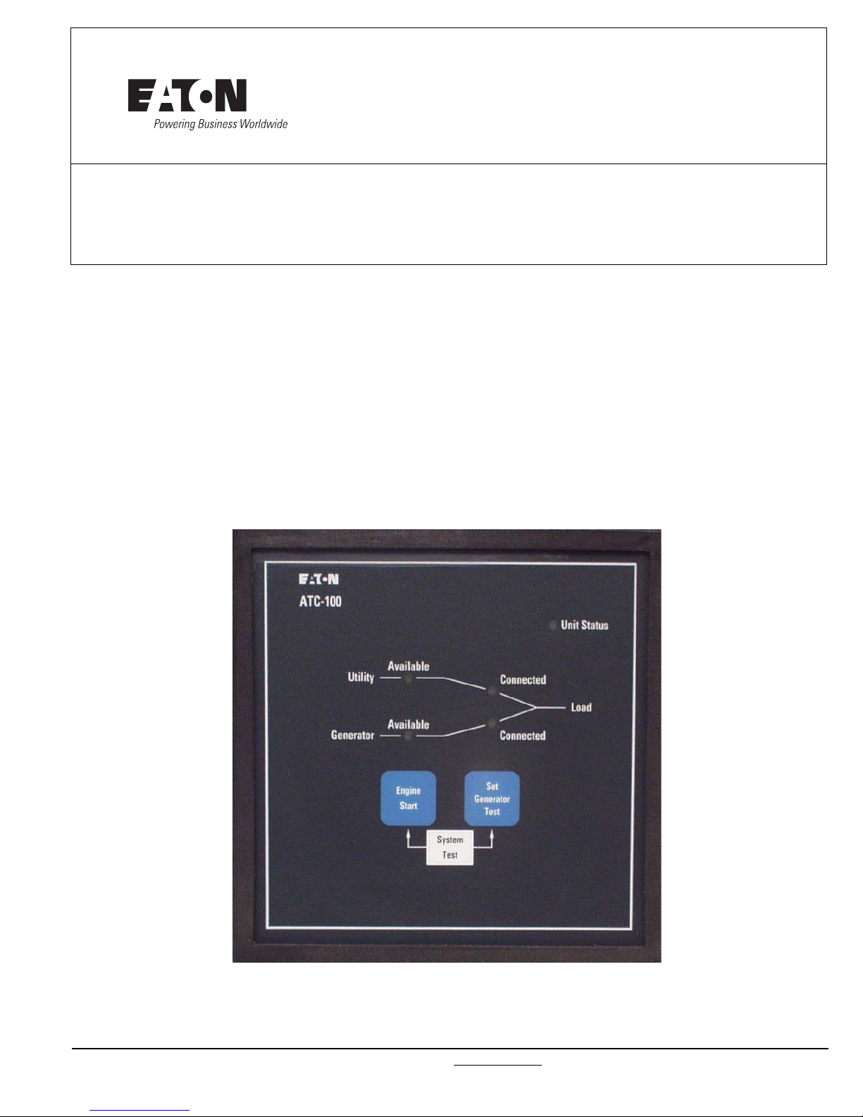
2.2 Front (Operator) Panel
The front panel, depending on the installation, is normally accessible from the outside of a panel or door. The front panel provides a
means to:
• alert the user to specific conditions;
• perform an Engine Start;
• perform a System Test; and
• program a Generator Test.
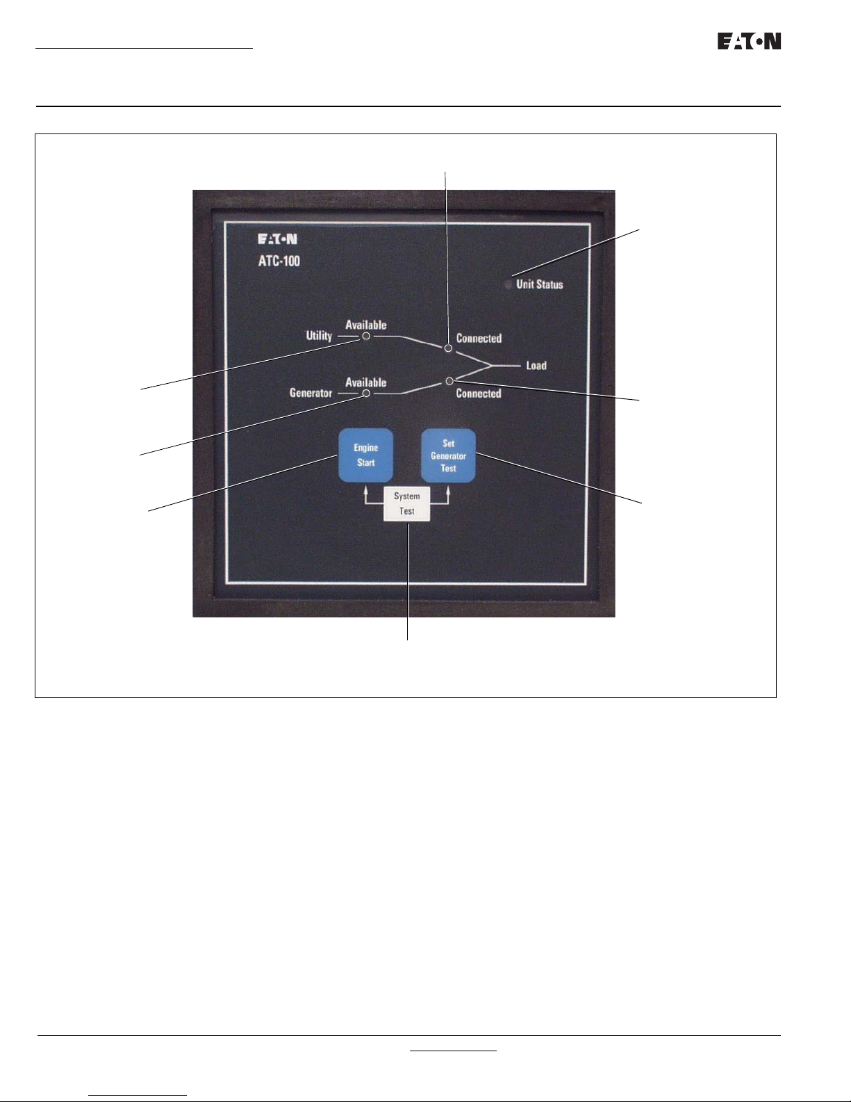
The ATC-100 front panel serves two primary functions: output
and input (see Figure 1). The output function consists of five LED
outputs:
1. Unit Status;
2. Utility Available;
3. Utility Connected;
4. Generator Available; and
5. Generator Connected.
There are three input functions accessible through the pushbuttons:
1. Engine Start;
2. Set Generator Test; and
3. System Test.
IB01602019E For more information visit: www.eaton.com
Instructional Booklet
UTILITY CONNECTED
UNIT STATUS
GENERATOR
CONNECTED
SET GENERATOR
TEST
SYSTEM TEST
ENGINE START
GENERATOR
AVAILABLE
UTILITY
AVAILABLE
Page 6 Effective: March 2010
O&M Manual for the Eaton ATC-100
Automatic Transfer Switch Controller
Figure 1. The ATC-100 Front Panel.
For more information visit: www.eaton.com IIB01602019E
 Loading...