

Eaton ASY-0652, ASY-0675 User Manual

Eaton® 9170
+
Battery Charger Module
Models ASY-0652 and ASY-0675
User’s Guide

Class A EMC Statements
WARNING
FCC Part 15
NOTE This equipment has been tested and found to comply with the limits for a Class A digital
This is a product for restricted sales distribution to informed partners. Installation restrictions or
additional measures may be needed to prevent electromagnetic disturbances.
device, pursuant to part 15 of the FCC Rules. These limits are designed to provide reasonable
protection against harmful interference when the equipment is operated in a commercial
environment. This equipment generates, uses, and can radiate radio frequency energy and, if
not installed and used in accordance with the instruction manual, may cause harmful
interference to radio communications. Operation of this equipment in a residential area is
likely to cause harmful interference in which case the user will be required to correct the
interference at his own expense.
W A R N I N G
Eaton is a registered trademark of Eaton or its subsidiaries and affiliates. All other trademarks are property of
their respective companies.
Copyright 2002-2015 Eaton, Raleigh, NC, USA. All rights reserved. No part of this document may be
reproduced in any way without the express written approval of Eaton.
Special Symbols
The following are examples of symbols used on the product to alert you to important information:
RISK OF ELECTRIC SHOCK - Observe the warning associated with the risk
of electric shock symbol.
CAUTION: REFER TO OPERATOR'S MANUAL - Refer to your operator's
manual for additional information, such as important operating and
maintenance instructions.
This symbol indicates that you should not discard waste electrical or
electronic equipment (WEEE) in the trash. For proper disposal, contact your
local recycling/reuse or hazardous waste center.


Table of Contents
1 INTRODUCTION . . . . . . . . . . . . . . . . . . . . . . . . . . . . . . . . . . . . . . . . . . . . . . . . . . . . . . . . . . . . . . . . . . . . . . . . 7
2 INSTALLATION . . . . . . . . . . . . . . . . . . . . . . . . . . . . . . . . . . . . . . . . . . . . . . . . . . . . . . . . . . . . . . . . . . . . . . . . . 11
3 OPERATION. . . . . . . . . . . . . . . . . . . . . . . . . . . . . . . . . . . . . . . . . . . . . . . . . . . . . . . . . . . . . . . . . . . . . . . . . . . . 15
4 SPECIFICATIONS . . . . . . . . . . . . . . . . . . . . . . . . . . . . . . . . . . . . . . . . . . . . . . . . . . . . . . . . . . . . . . . . . . . . . . . 17
5 TROUBLESHOOTING . . . . . . . . . . . . . . . . . . . . . . . . . . . . . . . . . . . . . . . . . . . . . . . . . . . . . . . . . . . . . . . . . . . . 23
Physical Features. . . . . . . . . . . . . . . . . . . . . . . . . . . . . . . . . . . . . . . . . . . . . . . . . . . . . . . . . . . . . . . . 7
Cabinet Preparation . . . . . . . . . . . . . . . . . . . . . . . . . . . . . . . . . . . . . . . . . . . . . . . . . . . . . . . . . . . . . . 11
DC Cabling Between Cabinets . . . . . . . . . . . . . . . . . . . . . . . . . . . . . . . . . . . . . . . . . . . . . . . . . . . . . 12
Setting DIP Switches. . . . . . . . . . . . . . . . . . . . . . . . . . . . . . . . . . . . . . . . . . . . . . . . . . . . . . . . . . . . . 12
Output Current Limit . . . . . . . . . . . . . . . . . . . . . . . . . . . . . . . . . . . . . . . . . . . . . . . . . . . . . . . . . 12
Periodic Float Charge . . . . . . . . . . . . . . . . . . . . . . . . . . . . . . . . . . . . . . . . . . . . . . . . . . . . . . . . 13
Reserved Switch . . . . . . . . . . . . . . . . . . . . . . . . . . . . . . . . . . . . . . . . . . . . . . . . . . . . . . . . . . . . 13
Battery Charger Module Installation . . . . . . . . . . . . . . . . . . . . . . . . . . . . . . . . . . . . . . . . . . . . . . . . . 13
UPS Cabinet Operation . . . . . . . . . . . . . . . . . . . . . . . . . . . . . . . . . . . . . . . . . . . . . . . . . . . . . . . . . . . 15
External Battery Cabinet Operation . . . . . . . . . . . . . . . . . . . . . . . . . . . . . . . . . . . . . . . . . . . . . . . . . . 15
Output Foldback . . . . . . . . . . . . . . . . . . . . . . . . . . . . . . . . . . . . . . . . . . . . . . . . . . . . . . . . . . . . . . . . 15
Alarm Messages . . . . . . . . . . . . . . . . . . . . . . . . . . . . . . . . . . . . . . . . . . . . . . . . . . . . . . . . . . . . . . . . 23
Audible Alarms and UPS Conditions . . . . . . . . . . . . . . . . . . . . . . . . . . . . . . . . . . . . . . . . . . . . . . . . . 23
Battery Charger Module Replacement . . . . . . . . . . . . . . . . . . . . . . . . . . . . . . . . . . . . . . . . . . . . . . .23
Service and Support. . . . . . . . . . . . . . . . . . . . . . . . . . . . . . . . . . . . . . . . . . . . . . . . . . . . . . . . . . . . . . 24
Eaton 9170+ Battery Charger Module (Models ASY-0652 and ASY-0675) User’s Guide 164201399 —Rev F www.eaton.com/powerquality 5

Table of Contents
6 Eaton 9170+ Battery Charger Module (Models ASY-0652 and ASY-0675) User’s Guide 164201399 —Rev F www.eaton.com/powerquality
Chapter 1 Introduction
The optional Eaton 9170+ battery charger module is designed to provide additional current for faster recharging
of uninterruptible power system (UPS) battery modules in systems with many batteries.
NOTE To realize maximum module functionality, install battery charger modules in the UPS
For systems with especially long runtime requirements, DIP switches on the rear panel of the battery charger
module make it possible to install the module in a specially designed external battery cabinet (ASY-0739).
The battery charger module is capable of providing up to 20 amperes of current for optimum charging, based
upon the condition and number of batteries in the system.
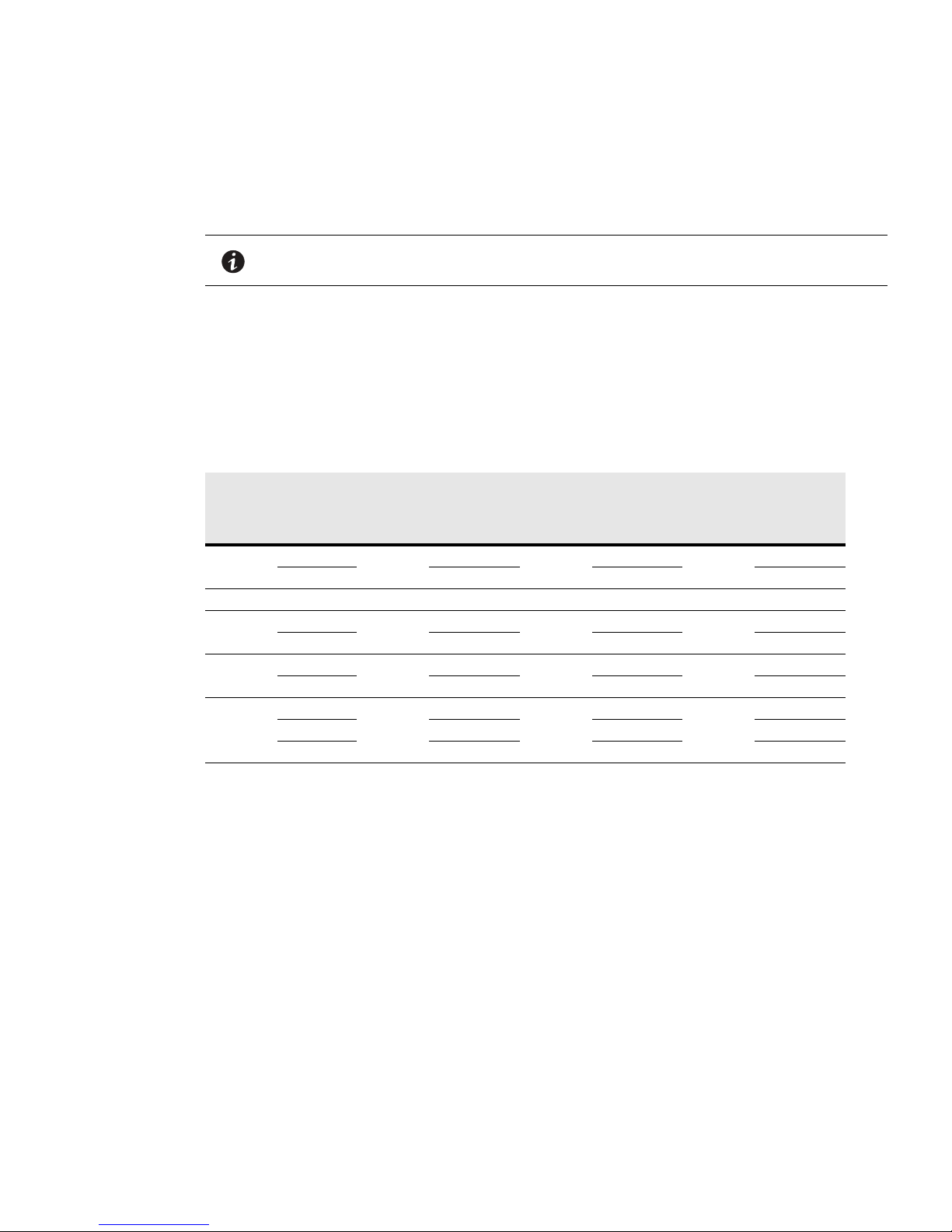
Examples of improved system recharge times are shown in Table 1. Note that larger systems require at least
one (or more) battery charger modules to be able to recharge the larger number of battery modules.
Table 1. Recharge Times Using Battery Charger Modules
Designed
Runtime
(Minutes)
58
12012855688211
240
360
480
Number of
cabinet.
6 kVA Capacity 12 kVA Capacity 18 kVA Capacity
Battery
Charger
Modules
0
1346
1
26 9 13
1
2 7 14 19
1
210 18 26
3 7 13 18
Battery
Modules
16
54
78
102
Recharge
Time (Hours)
20
9
14
18
Battery
Modules
32
110
160
200
Recharge
Time (Hours)
20
17
N/A
N/A
Battery
Modules
48
160
234
308
Recharge
Time (Hours)
20
N/A
N/A
N/A
Physical Features
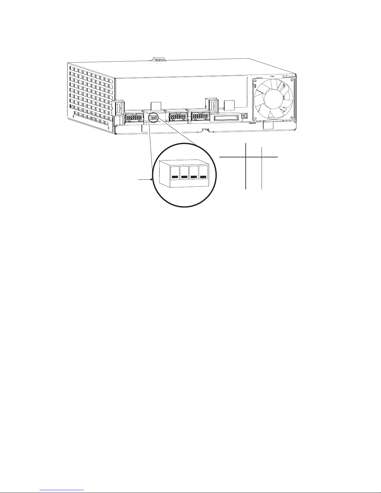
The battery charger module is similar in appearance to a power module. The two primary differences are the
front label color (light-purple for the ASY-0652 and orange for the ASY-0675) and the current-limit DIP switch on
the rear panel of the module as shown in Figure 1. See “Setting DIP Switches” on page 12 for more information
on DIP switch functions.
The module may be installed in either the UPS cabinet (6-, 9-, and 12-slot sizes) or a special 12-slot external
battery cabinet.
Eaton 9170+ Battery Charger Module (Models ASY-0652 and ASY-0675) User’s Guide 164201399 —Rev F www.eaton.com/powerquality 7
Introduction
On
Off
On
1
2
3
4
Current
Limit
12
5A Off Off*
10A Off
Off15A On
On20A On
DIP Switch Detail
* Factory default setting
Figure 1. Battery Charger Module (Rear View)
The external battery cabinet may have input power hardwired through rigid or flexible conduit, as shown in
Figure 2, or input power may be supplied through a plug-terminated line cord (requires the purchase of a line
cord kit). Besides input power, the external battery cabinet has a cable or conduit connection to the UPS
cabinet. It may also have a cable or conduit to additional external battery cabinets.
8 Eaton 9170+ Battery Charger Module (Models ASY-0652 and ASY-0675) User’s Guide 164201399 —Rev F www.eaton.com/powerquality

Introduction
To UPS or Previous
External Battery Cabinet
AC Line In
DC Emergency
Disconnect Switch
Button
To Next External
Battery Cabinet
Figure 2. External Battery Cabinet for Charger Modules
Eaton 9170+ Battery Charger Module (Models ASY-0652 and ASY-0675) User’s Guide 164201399 —Rev F www.eaton.com/powerquality 9
 Loading...