

Eaton ARCON 2.0 Series, ARCON ARC-EP10-2/2.0, ARCON ARC-EP10/2.0, ARCON ARC-EM/2.0, ARCON ARC-EC1/2.0 Operation And Configuration Instructions. Technical Description
...
ARCON® 2.0
Arc protection system
Operation and confi guration instructions
Technical description
www.eaton.eu/documentation
MA_Arcon_en.qxd/04.2018b / MN014007ENEaton Industries (Austria) GmbH, Eugenia 1, A-3943 Schrems
1

Table of Contents
1. General ........................................................................................................ 5
1.1. ARCON 2.0 arc protection system components ............................................................ 5
1.1.1. Master unit ARC-EM/2.0 ................................................................................... 6
1.1.2. I/O units ARC-EP10-2/2.0, ARC-EP10/2.0, ARC-EL3/2.0 and ARC-EC1/2.0 .. 7
1.1.3. Quenching device ARC-AT ............................................................................... 8
1.1.4. Arc sensors ARC-SP, ARC SL and ARC-SM.................................................... 9
1.1.5. Other system components ...................................................................................
10
1.2. Operational safety ........................................................................................................ 10
2. User interface ................................................................................................ 11
2.1. Front panel of the master unit ARC-EM/2.0 ................................................................. 11
2.1.1. Display and status indications ......................................................................... 12
2.1.2. Buttons and programming switches ................................................................ 13
2.1.3. Moving in menus ............................................................................................. 14
2.2. I/O unit ........................................................................................................................ 15
2.2.1. ARC-EP10-2/2.0.............................................................................................. 16
2.2.2. ARC-EP10/2.0 ................................................................................................. 17
2.2.3. ARC-EL3/2.0 ................................................................................................... 18
2.2.4. ARC-EC1/2.0................................................................................................... 19
3. ARCON 2.0 arc protection system operation and troubleshooting .......... 20
3.1. System status indications ............................................................................................ 20
3.1.1. Arc fault ........................................................................................................... 21
3.1.2. Overcurrent alarm ........................................................................................... 22
3.1.3. Self-supervision alarm ..................................................................................... 23
3.1.4. Fault codes ...................................................................................................... 24
3.2. Using programming switches ....................................................................................... 28
3.2.1. Master unit’s programming switches ............................................................... 28
3.2.2. Programming switches - I/O units ................................................................... 29
3.3. Adjusting the overcurrent setting ................................................................................. 32
3.4. Confi guration of the arc protection system .................................................................. 34
3.4.1. Checking system confi guration ....................................................................... 35
4. System commissioning ................................................................................ 36
4.1. Testing - general .......................................................................................................... 36
4.2. Performing the testing .................................................................................................. 36
4.3. Periodic commissioning ............................................................................................... 36
5. Introduction ................................................................................................... 37
5.1. Purpose ........................................................................................................................ 37
5.2. Main properties ............................................................................................................ 37
2

6. Functions ...................................................................................................... 38
6.1. Protection functions ..................................................................................................... 38
6.1.1. Arc (fault) protection ....................................................................................... 38
6.1.2. Circuit breaker failure protection stage ........................................................... 38
6.2. Measurements ............................................................................................................. 39
6.3. Output relay functions .................................................................................................. 39
6.4. Self-supervision ........................................................................................................... 39
6.5. BI/O bus interface ........................................................................................................ 40
6.5.1. Connection to I/O unit...................................................................................... 41
6.5.2. Connection to quenching device ARC-AT ...................................................... 41
7. Interfaces ......................................................................................................42
7.1. Rear panel view ........................................................................................................... 42
7.1.1. ARC-EP10-2/2.0.............................................................................................. 45
7.1.2. ARC-EP10/2.0 ................................................................................................. 46
7.1.3. ARC-EL3/2.0 .................................................................................................. 47
7.1.4. ARC-EC1/2.0................................................................................................... 48
7.2. Analogue measurements ............................................................................................. 49
7.3. Digital inputs (BI/O bus) ............................................................................................... 49
7.4. Auxiliary power supply ................................................................................................. 49
7.5. Output relays ................................................................................................................ 50
7.5.1. ARC-EM/2.0 .................................................................................................... 50
7.5.2. ARC-EP10/2.0, ARC-EL3/2.0 and ARC-EC1/2.0 ............................................ 50
7.5.3. ARC-EP10-2/2.0.............................................................................................. 50
7.6. Block diagram .............................................................................................................. 51
7.6.1. ARC-EM/2.0 .................................................................................................... 51
7.6.2. ARC-EP10-2/2.0.............................................................................................. 52
7.6.3. ARC-EP10/2.0 ................................................................................................. 53
7.6.4. ARC-EL3/2.0 ................................................................................................... 54
7.6.5. ARC-EC1/2.0................................................................................................... 54
8. Technical data ............................................................................................... 55
8.1. Connections ................................................................................................................. 55
8.1.1. Measuring circuits ........................................................................................... 55
8.1.2. Auxiliary power supply..................................................................................... 56
8.1.3. Digital inputs (BI/O bus) .................................................................................. 57
8.1.4. Trip contacts .................................................................................................... 58
8.1.5. Alarm contacts................................................................................................. 59
8.1.6. Communication bus interface .......................................................................... 59
8.1.7. Local serial communication port ...................................................................... 59
8.2. Tests and environmental conditions ............................................................................ 60
8.2.1. Electrical safety tests....................................................................................... 60
8.2.2. Mechanical tests.............................................................................................. 61
8.2.3. Environmental conditions ................................................................................ 61
8.2.4. Casing ............................................................................................................. 61
8.2.5. Package .......................................................................................................... 62
8.3. Protection stages ......................................................................................................... 63
8.3.1. Arc (fault) protection ........................................................................................ 63
8.3.2. Circuit breaker failure protection stage (50BF)................................................ 63
3

9. Construction .................................................................................................. 64
9.1. Dimensional drawings .................................................................................................. 64
9.1.1. ARC-EM/2.0 panel mounting and self-fl ush .................................................... 64
9.1.2. ARC-EP10-2/2.0 din rail mounting .................................................................. 65
9.1.3. ARC-EP10/2.0 din rail mounting ..................................................................... 66
9.1.4. ARC-EL3 din rail mounting .............................................................................. 67
9.1.5. ARC-EC1/2.0 din rail mounting ....................................................................... 68
9.1.6. Fiber sensor mounting..................................................................................... 69
9.1.7. Point sensor mounting..................................................................................... 70
9.1.8. ARC-SP ........................................................................................................... 71
9.2. Unit installation ............................................................................................................. 71
9.2.1. ARC-EM/2.0 .................................................................................................... 72
9.2.2. I/O units ........................................................................................................... 74
9.2.3. Connecting separate auxiliary power supplies ................................................ 75
9.2.4. Arc sensors ..................................................................................................... 77
9.2.5. Multiple master connection via BI/O bus interface ...........................................80
9.2.6. Appendix/Earthing instructions ........................................................................ 81
10. Application examples ................................................................................... 82
10.1. Applications .................................................................................................................. 82
10.1.1. With a main busbar system ............................................................................. 82
10.1.2. With two main busbar systems........................................................................ 83
10.1.3. With two main busbar systems and additional zone selection (4 zones) ........ 84
4
1. General
This fi rst part, Operation and confi guration instructions, of the Manual contains a general de-
scription of and user instructions for the ARCON 2.0 Arc Protection System components and
functions. This section also includes parametering and confi guration instructions and instruc-
tions for changing the setting values.
The second part, Technical description, contains a detailed description of the protection func-
tions, application examples and technical data.
1.1. ARCON 2.0 arc protection system components
ARCON 2.0 is an easily adaptable arc protection system for the protection of electricity distri-
bution systems. ARCON 2.0 signifi cantly reduces the risk of potential personal damage, and
material and production losses caused by arc fault.
ARCON 2.0 benchmark data:
• system operating time 6..8 milliseconds (trip relay output)
1..2 milliseconds (triggering quenching device)
• accurate location of arc fault
• four selective protection zones
• self-supervision of the entire system
• system cabling with standard cables
• automatic system confi guration
• phase current measuring
• earth-fault current measuring
ARCON 2.0 complies with the latest standards concerning the electromagnetic compliance
(EMC) of protective relays.
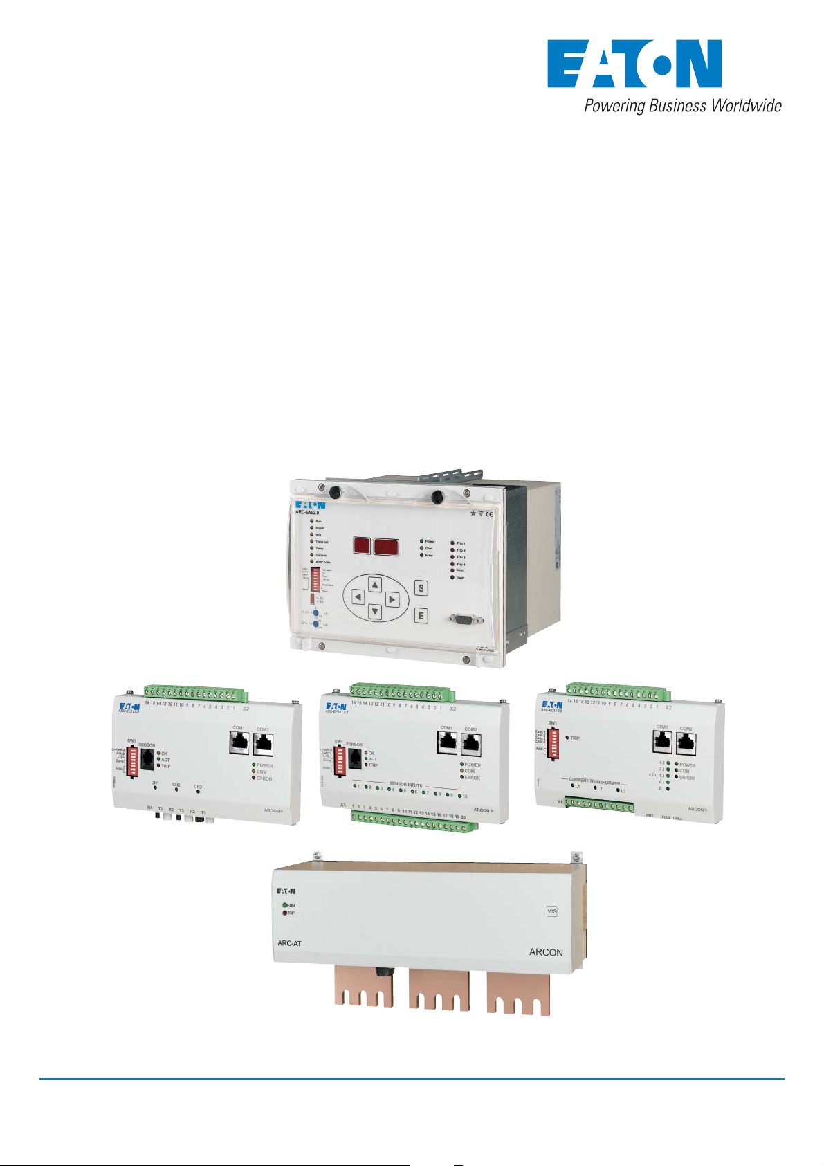
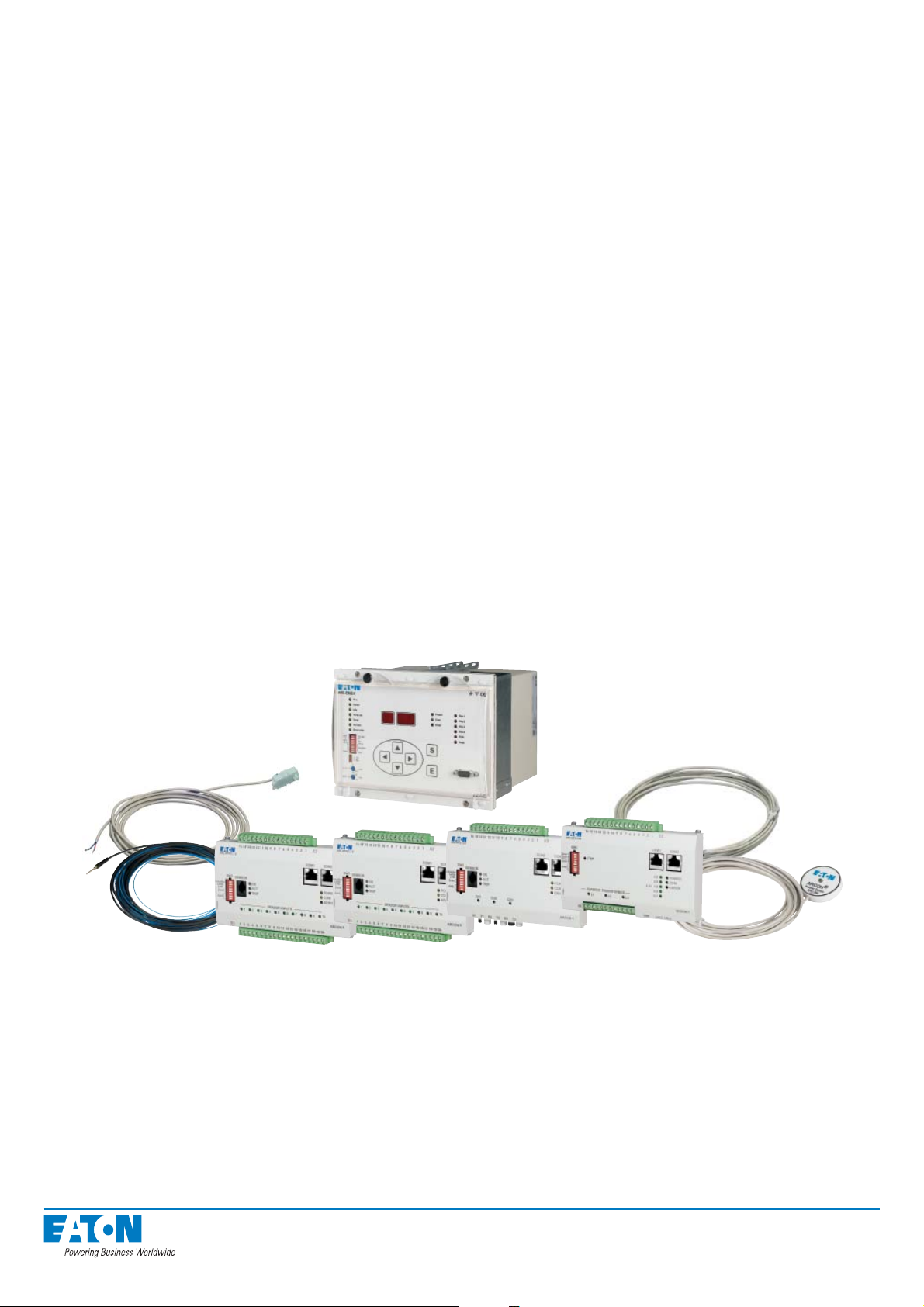
Figure: ARCON 2.0 Arc Protection System
ARCON 2.0 is a modular system consisting of a master unit, I/O units, arc sensors and the
quenching device.
Thanks to its modularity, the system can easily be adapted to different targets requiring arc
protection, from simple systems comprising one master unit and one I/O unit to versatile
selective systems comprising several master units.
The ARCON 2.0 arc protection system is suitable for low voltage switchgear systems. In ad-
dition to new switchgear, the system can also be installed on existing switchgear.
5

1.1.1. Master unit ARC-EM/2.0
Figure: The master unit ARC-EM/2.0
The master unit ARC-EM/2.0 contains the following functions:
• 3-phase overcurrent and arc stage
• Alternatively, 2-phase overcurrent, earth-fault and arc stage
• Circuit breaker failure protection stage
(CBFP - not relevant for applications with quenching device)
• Optional trip criteria (I>&L>, I0>&L> or L>)
• Two mutually independent tripping groups
• Four output trip relays
• Four protection zones
• BI/O bus for light and overcurrent information
• Status, fault and trip indications
• Accommodates up to 16 I/O units
• System self-supervision
6
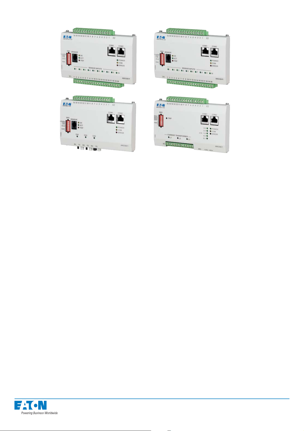
1.1.2. I/O units ARC-EP10-2/2.0, ARC-EP10/2.0, ARC-EL3/2.0, and ARC-EC1/2.0
Figure: I/O units ARC-EP10-2/2.0, ARC-EP10/2.0 , ARC-EL3/2.0 and ARC-EC1/2.0
• Sensors are connected to the master unit via I/O units
• ARC-EP10-2/2.0 accommodates up to 10 arc sensors
3 sensors with dedicated trip outputs
• ARC-EP10/2.0 accommodates up to 10 arc sensors
• ARC-EL3/2.0 accommodates up to 3 fi bre loops
• ARC-EC1/2.0 accommodates up to 3 current transformers
• ARC-EP10-2/2.0 is equipped with 3 output trip relays
• ARC-EP10/2.0, ARC-EL3/2.0 / ARC-EC1/2.0 are equipped with one output trip relay
• Indication of active sensor
• Protection zone addresses (max. 4 zones)
• Detachable external wiring terminal blocks
(does not apply to the current terminals of ARC-EC1/2.0)
• Connection for a portable arc sensor (ARC-EP10/2.0 and ARC-EL3/2.0)
• Free placement in the switchgear
• Intra-unit cabling with factory-made modular cable or instrumentation cable
7
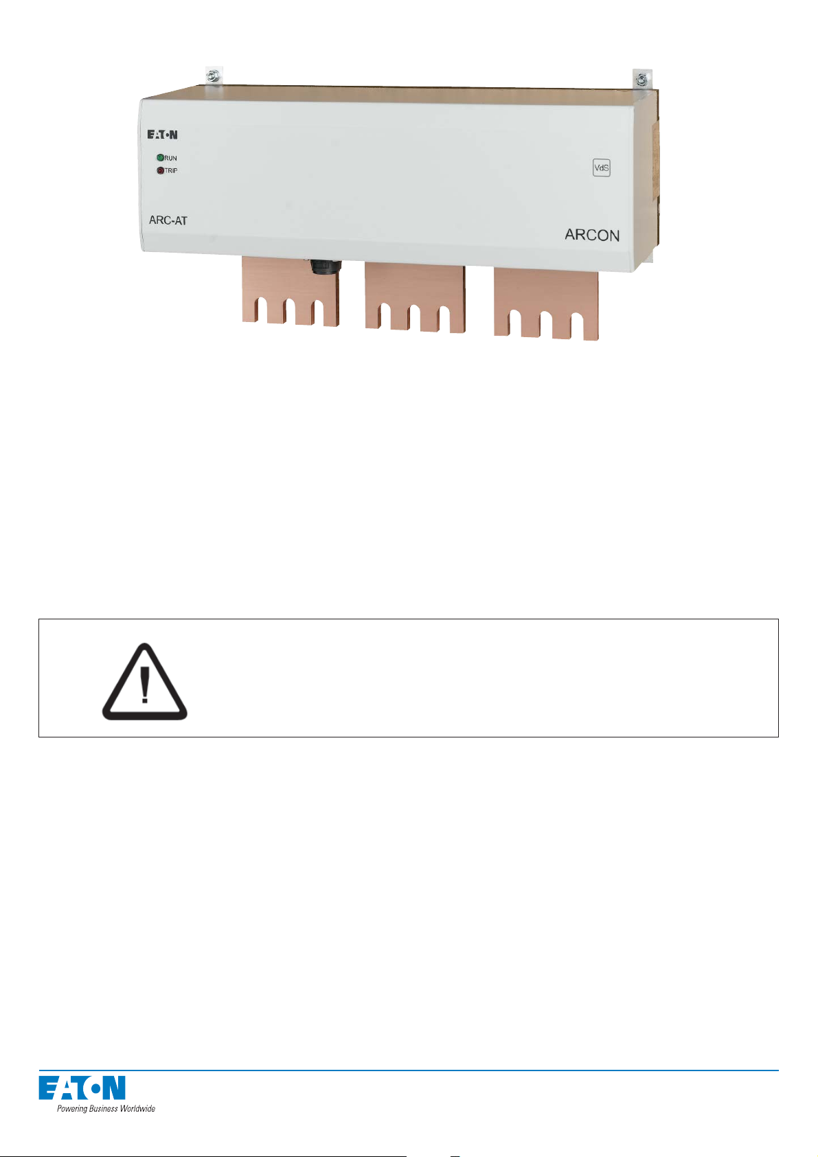
1.1.3 Quenching device ARC-AT
Figure: ARCON quenching device ARC-AT-T
The quenching device ARC-AT-… is a 3-pole rapid shorting device. Its function is to extin-
guish the arc fault.
Two pyrotechnic pressure elements serve as the switching drive, providing the necessary energy upon tripping to drive the switch.
In case of a busbar selective system structure one quenching device per busbar segment has
to be installed in the low voltage switchgear.
Special Information for quenching device ARC-AT-...
With regard to the lifespan of the pyrotechnic actuators it is recommended that the quenching
device ARC-AT-... is to be replaced after 12 years of service.
Danger
You are not allowed to open the ARCON quenching device ARC-AT-... under
any circumstances. It contains pyrotechnic objects that can explode and cause
serious injury, if handled improperly.
The replacement of the quenching device ARC-AT... can be done by Eaton After Sales Ser-
vice personnel. They have special training in handling pyrotechnical equipment and are authorized to conduct this kind of operation.
For an quote for the replacement of ARCON quenching device ARC-AT-... contact the Eaton
After Sales Service.
Disused quenching devices must be returned to the Eaton After Sales Service for proper dis-
posal.
8
1.1.4. Arc sensors ARC-SP, ARC-SL and ARC-SM
Sensors placed in the switchgear transfer the light information to the I/O units.
Arc sensor ARC-SP
Figure: Arc sensor ARC-SP
• Strong light is transformed to a current signal in the sensor
• ARC-EP10/2.0 transfers the current signal to the master unit
• Standard cable lengths 6 m and 20 m
• The sensor type offers a cost-effective arc protection solution
• Easy to install and replace
• Normal installation involves one sensor in each switchgear compartment
• Self-supervised arc sensor
Arc fi bre sensor ARC-SL
Figure: Arc fi bre sensor ARC-SL
• The fi bre sensor is a durable glass fi bre, which is manufactured in lengths of
10, 11, 12, 13, 15, 20 and 25 metres (the active sensor length is always 5m less)
• The detected light information is transferred to the ARC-EL3/2.0 unit inside the fi bre
• The fi bre will be installed to go through the supervised compartments
• Monitoring the light information with a fi bre system is a cost-effective solution
e.g. in low voltage switchgears with several compartments
• Self-supervised arc sensor
9
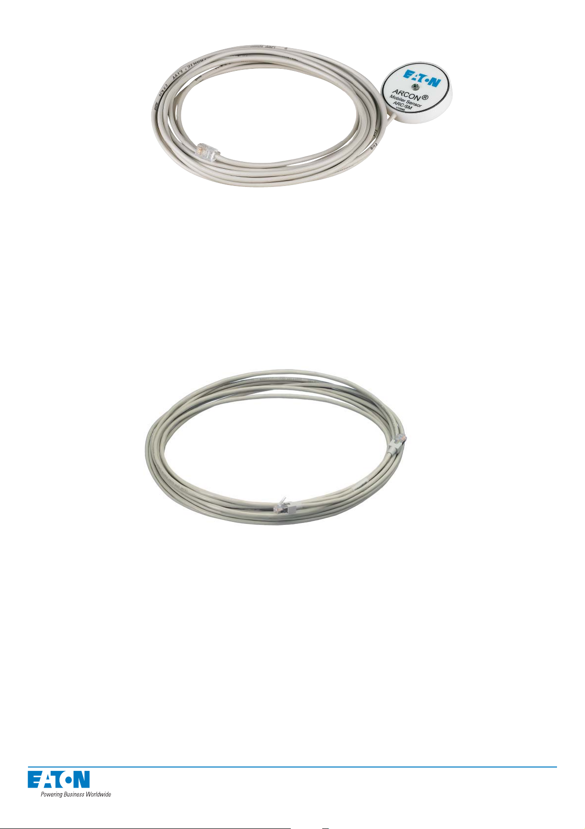
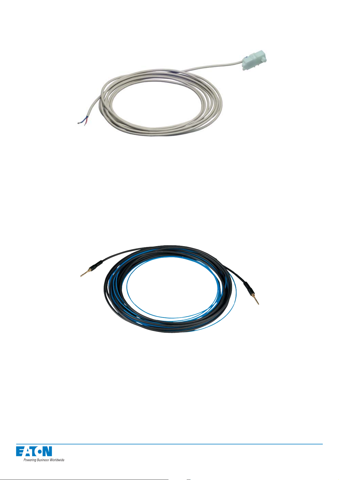
Portable arc sensor ARC-SM
Figure: Portable arc sensor ARC-SM
• Improves personal safety when working with live voltage switchgear.
• The sensor is to be connected to the nearest light I/O unit (ARC-EP10/2.0 or
ARC-EL3/2.0) using a snap-in connector
• Cable length 5 metres
• The sensor is designed to be attached e.g. to the edge of a pocket in the technician’s
working wear
1.1.5. Other system components
Modular cable ARC-CC
Figure: Modular cable ARC-CC
The I/O and master units are to be connected to each other using a modular cable approved
by the manufacturer. The cable is equipped with quick- disconnect connectors.
Modular cables are available in lengths of 0.5, 1, 2, 3, 5, 7, 10, 15, and 20 metres.
NOTE! The total length of the modular or instrumentation cables of the system, measured from the
master unit to the furthest I/O unit, may not exceed 100 metres.
1.2. Operational safety
Dangerous voltages may occur at the terminal in the back panel of the master unit, even
though the auxiliary power supply has been disconnected. Do not open the secondary circuit
of a live current transformer. Disconnecting the secondary circuit of a live current transformer
may cause dangerous overcurrents! Always observe all national and regional regulations and
guidelines.
Read any instructions carefully before performing any operations.
10

2. User interface
The control and acknowledgement functions of the ARCON 2.0 arc protection system are
mainly carried out using the push buttons on the master unit. Information on equipment status
and operation can also be read on the master unit’s display and indicator lights.
2.1. Front panel of the master unit ARC-EM/2.0
Figure: Master unit ARC-EM/2.0 - front panel
ARC-EM/2.0
ARCON
®
The front panel of the master unit contains all the programming and control buttons, and the
DIP-switches that control the operation of the master unit.
11
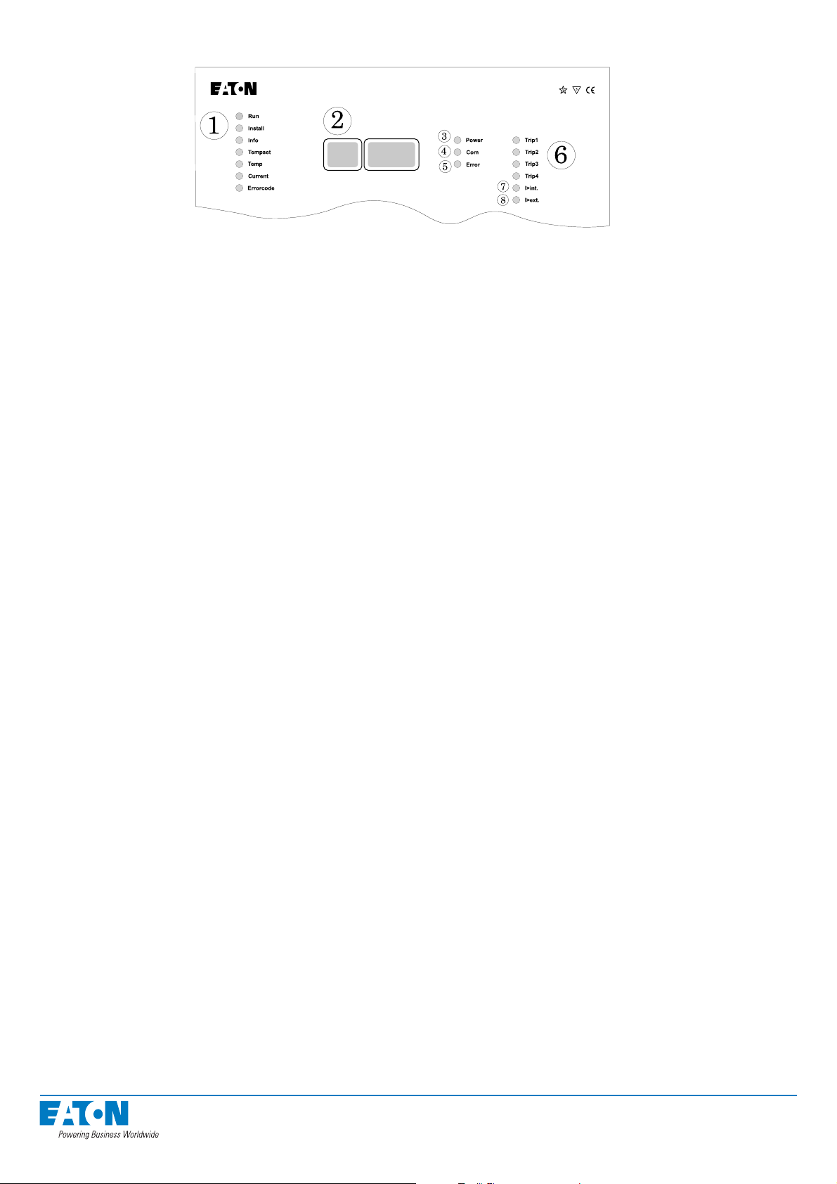
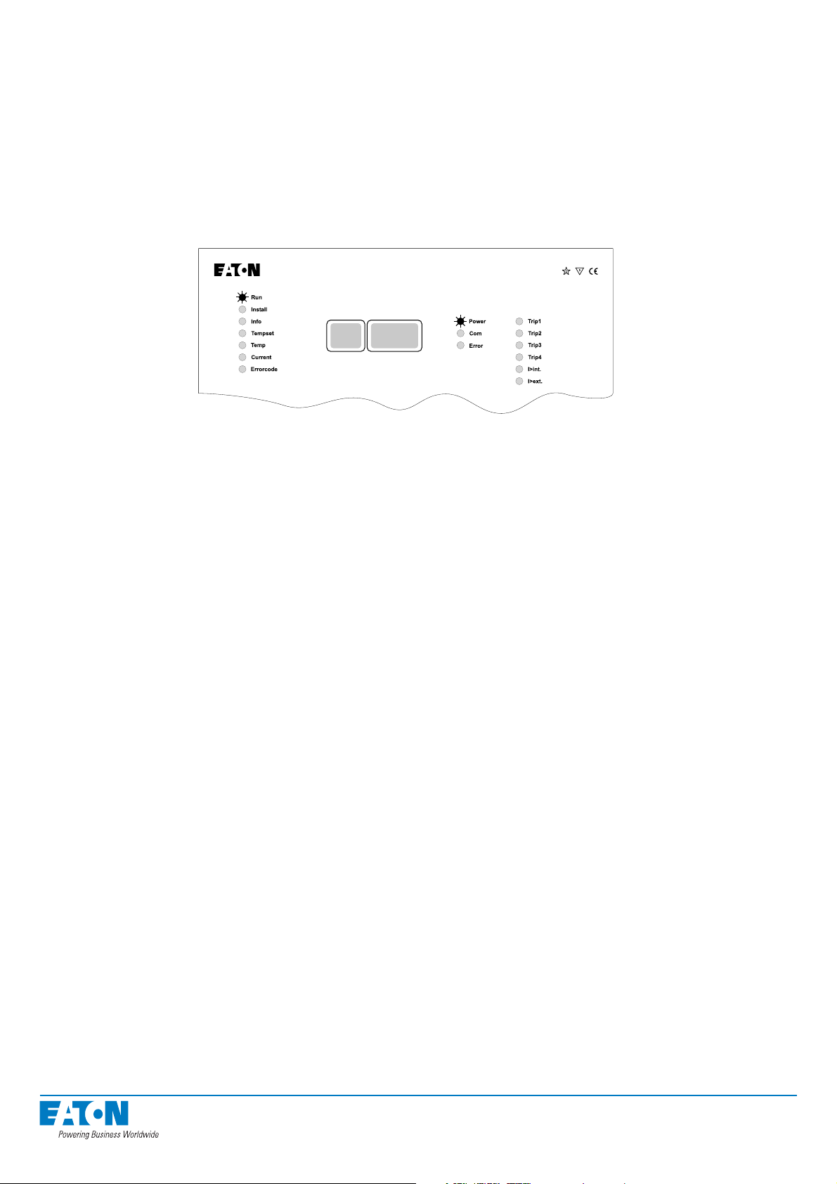
2.1.1. Display and status indications
ARC-EM/2.0
Figure: Master unit ARC-EM/2.0 - display and status indications
1. Operating status indication lights, see section ‘Moving in menus’
RUN normal operation
INSTALL system confi guration
INFO system confi guration check
TEMP SET reserved for future use
TEMP reserved for future use
CURRENT current setting limit and measurement indication
ERROR reading and resetting of fault memory
2. Display
3. POWER indicator light, indicates all supply voltages are in order.
4. COM indicator light, blinks in INSTALL mode when the master units and I/O units are
communicating.
5. ERROR indicator light, indicates internal fault detected by the relay self-diagnostics.
NOTE! The light also blinks dimly in normal operating mode (visible only in the dark).
6. Trip indication lights, indicate which trip stages have been activated.
7. I>int LED light, indicates overcurrent activation of the master unit.
8. I>ext LED light, indicates overcurrent activation outside the master unit.
NOTE! Any rippling in the display is due to its refresh rate.
NOTE! Moving in the operating menus does not affect the operation of the arc protection; the system
is ready to activate once the system has been confi gured and while the master unit is con-
nected to an operating voltage.
12
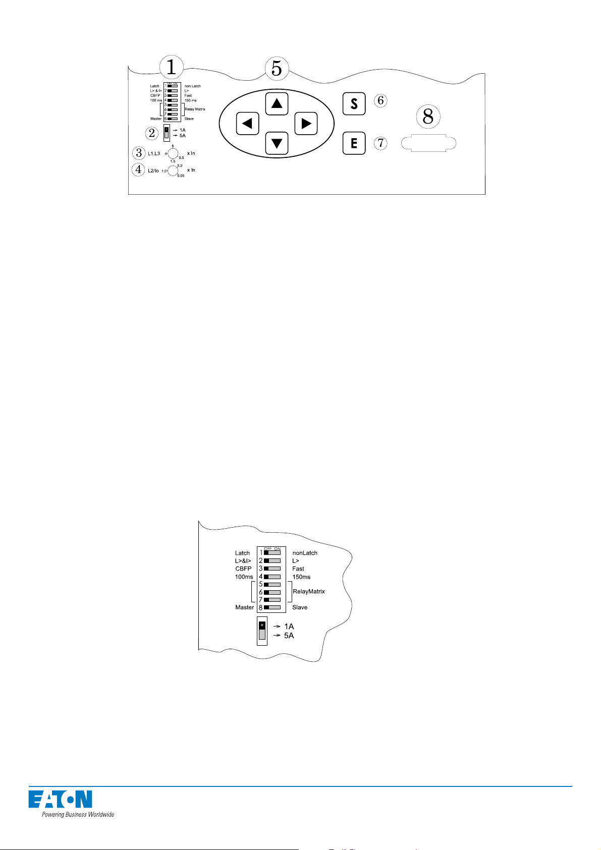
2.1.2. Buttons and programming switches
Figure: Buttons and programming switches
1. Programming switches for the trip relay matrix
(factory setting - all DIP switches in „OFF“ position)
NOTE! The confi guration of the DIP switches must be done properly before operating the system!
2. Selection switch for the secondary current of the current transformer
3. Overcurrent setting knob (IL1, IL3), setting range 0.5...6*In (factory setting 1.0*In)
4. Overcurrent setting knob (IL2, I0), setting range 0.05...5*In (factory setting 1.0*In)
NOTE! The confi guration of the overcurrent setting must be done properly before operating
the system!
5. Navigation keys
6. SET push button for activating functions
7. ENTER push button for executing functions
8. Communication port for loading software updates, not needed in normal operation.
For more details on the trip relay matrix, see section 3.2. Using programming switches.
Programming switches (factory setting):
All DIP switches are in „OFF“ position and the setting of the current transformer (CT) ratio is
on 1A.
13
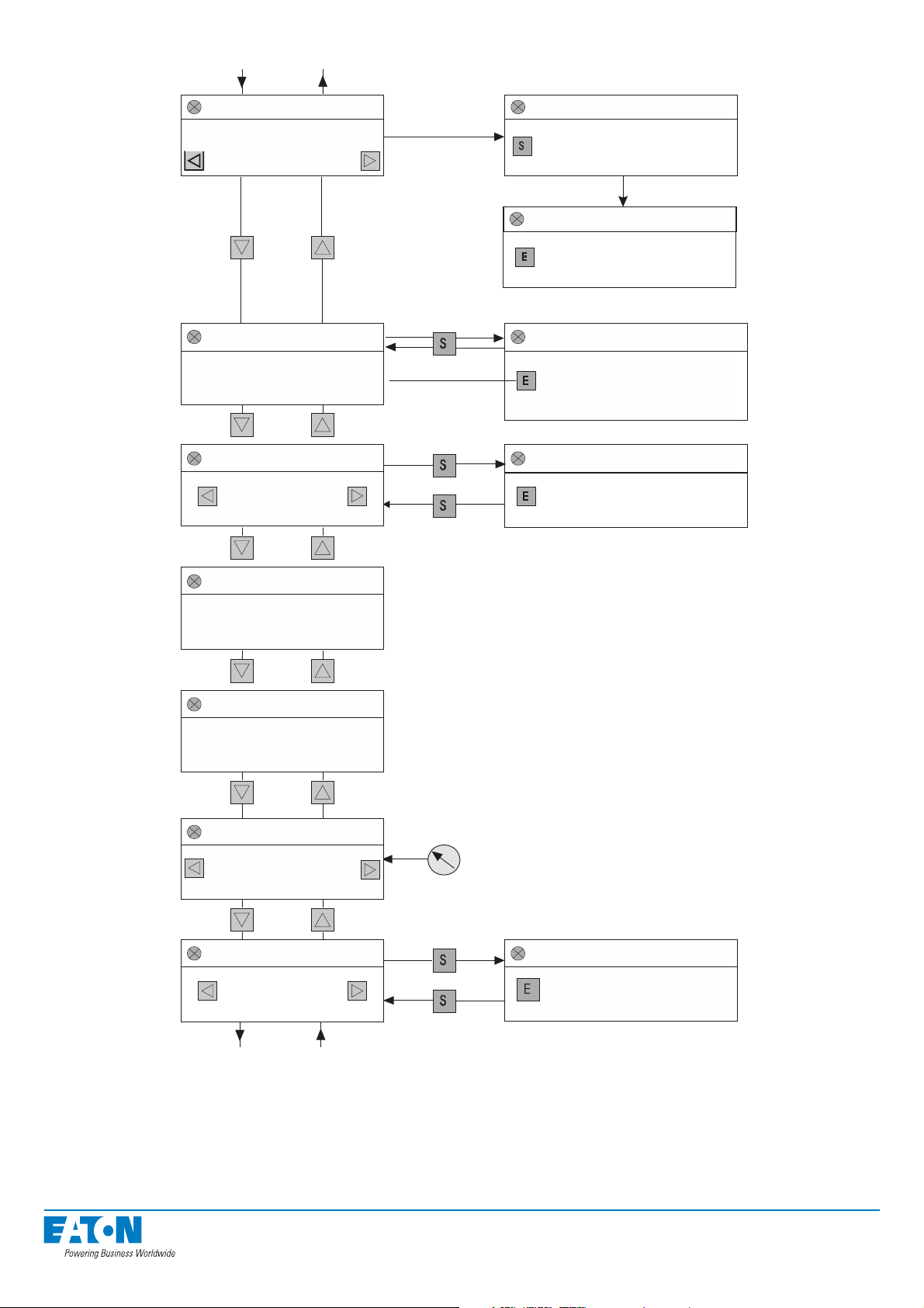
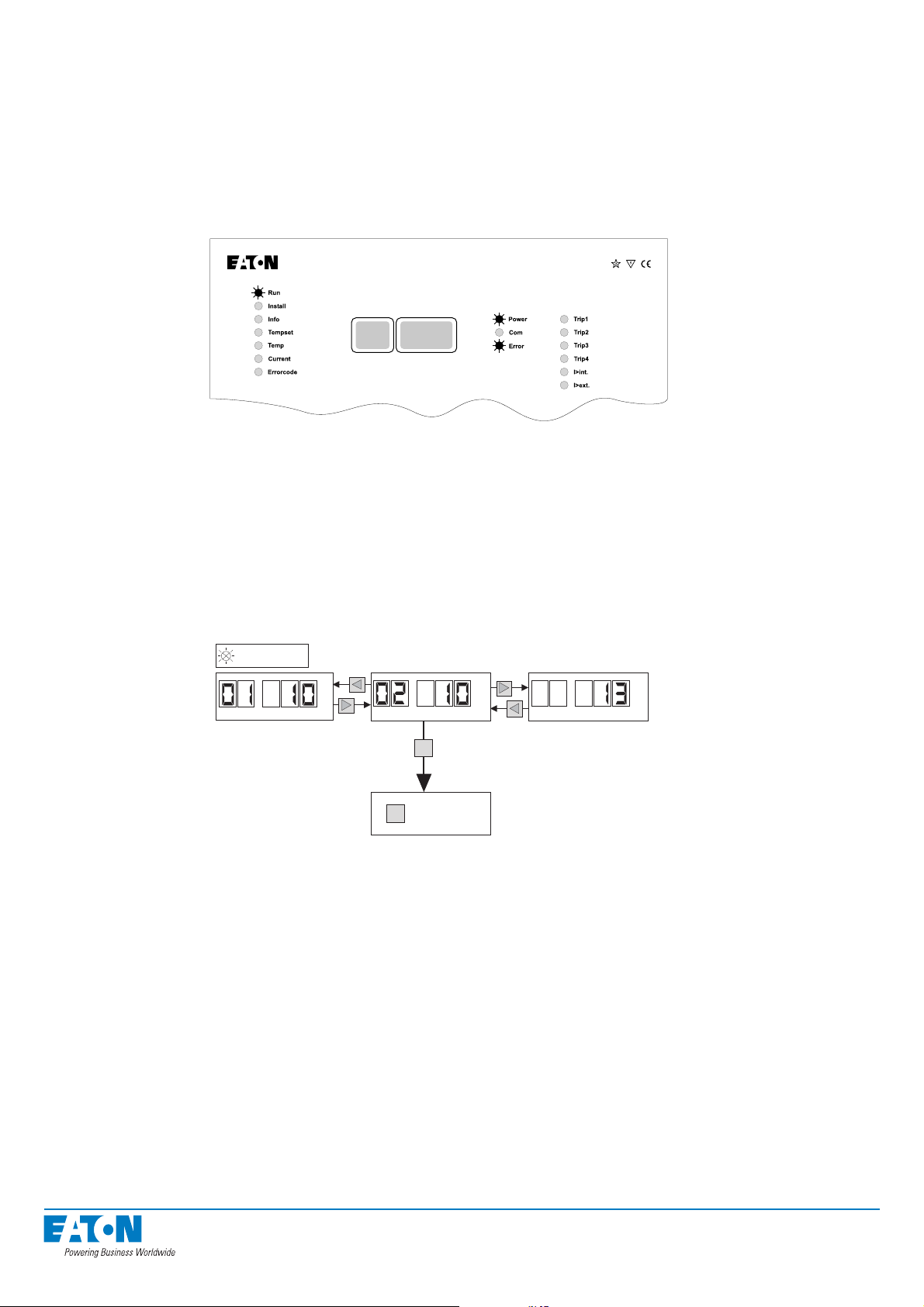
2.1.3. Moving in menus
RUN
Information of last
activation
(I/O unit no. / sensor no.)
INSTALL
Number of I/O units and
sensors connected to
master unit
INFO
Number of sensors
in specific
I/O unit
RUN
Use push-button for
reset I/O units indicators
and trip relays
RUN
Use push-button for
clearing the memory
INSTALL
Use push-button for
configurate the system
INFO
Use push-button for check
number of sensors connected
to active I/O unit
TEMP SET
Reserved for
future use
TEMP
Reserved for
future use
CURRENT
Indication of pick-up
current and
instantaneous currents
ERROR CODE
Sensor no. or
error code
Use the trimmer for adjust
the level of pick-up current
ERROR CODE
Use push-button for
clearing error codes (one
error code in time)
Figure: Moving in the mode menu
14

Select the operating status with the up and down navigation keys on the master unit.
To activate a function, use the S key. A blinking display indicates that the function has been
activated. Press E to confi rm the execution of an activated function. To cancel an activated
function, press S again.
Use the left and right navigation keys to browse parallel information; for example, you can
change the I/O unit you wish to view in the INFO mode or compare the current limit setting
values the measured earth-fault and/or phase currents.
NOTE! If you do not touch the buttons for one minute, the master unit automatically returns to the
normal operating mode (RUN). Regardless of which menu is displayed the arc system will always be ready to operate!
2.2. I/O unit
Usually, there is no need to touch the front panel during normal operation, since all the ne-
cessary information can be read from the master unit display. However, after a new installation or a system expand you will need to program certain functions (zone/address, trip output)
in the I/O unit.
NOTE! If you unfasten the terminal blocks during installation, remember to tighten the fi xing screws
after installation! Also tighten the screws even if you did not unfasten the blocks.
15
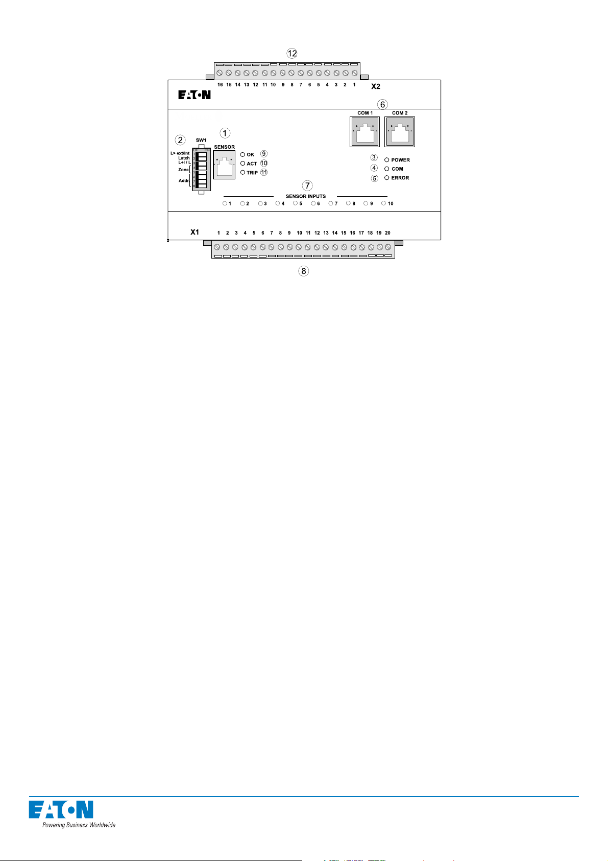
2.2.1. ARC-EP10-2/2.0
ARC-EP10-2/2.0
®
ARCON
Figure: Arc sensor I/O unit ARC-EP10-2/2.0
1. Connection for portable arc sensor (ARC-SM)
2. Programming switches (factory setting - all DIP switches in „OFF“ position)
NOTE! The confi guration of the DIP switches must be done properly before operating the system!
3. POWER indicator light, indicates that the supply voltages of each component are in order.
4. COM indicator light, lit when the master unit and I/O units are communicating.
5. ERROR indicator light, indicates an internal fault detected by the component’s self diagnostics. Such faults include faulty arc sensor or changes in the amount of sensors.
6. Connector sockets for the modular cables
7. LED lights indicating sensor activation
8. Terminal block for ten arc sensors
9. Portable arc sensor ARC-SM connected and operational
10. Portable arc sensor activated
11. I/O unit trip relays activated
12. Terminal block for output relay
16
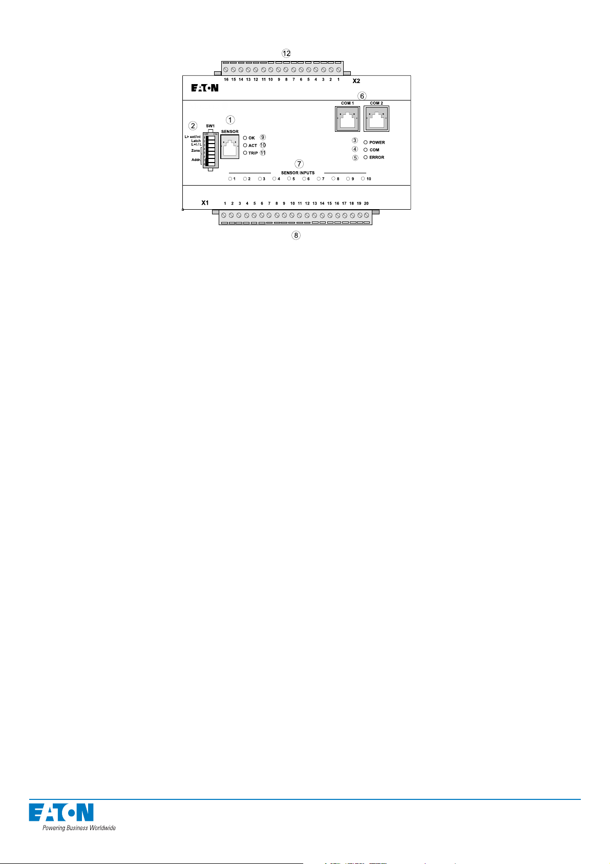
2.2.2. ARC-EP10/2.0
ARC-EP10/2.0
®
ARCON
Figure: Arc sensor I/O unit ARC-EP10/2.0 front panel
1. Connection for portable arc sensor (ARC-SM)
2. Programming switches (factory setting - all DIP switches in „OFF“ position)
NOTE! The confi guration of the DIP switches must be done properly before operating the system!
3. POWER indicator light, indicates that the supply voltages of each component are in order.
4. COM indicator light, lit when the master unit and I/O units are communicating.
5. ERROR indicator light, indicates an internal fault detected by the component’s self diagnostics. Such faults include faulty arc sensor or changes in the amount of sensors.
6. Connector sockets for the modular cables
7. LED lights indicating sensor activation
8. Terminal block for ten arc sensors
9. Portable arc sensor ARC-SM connected and operational
10. Portable arc sensor activated
11. I/O unit trip relay activated
12. Terminal block for external communication and BI/O channels and trip signal
17
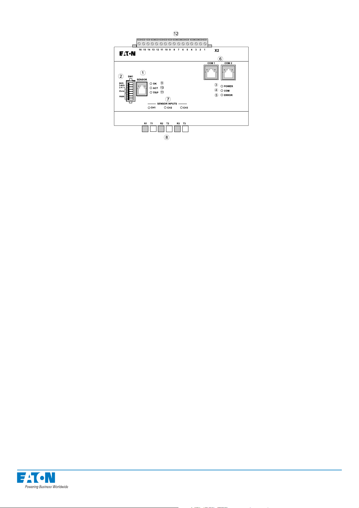
2.2.3. ARC-EL3/2.0
ARC-EL3/2.0
®
ARCON
Figure: Arc fi bre sensor I/O unit ARC-EL3/2.0 front panel
1. Connection for portable arc sensor (ARC-SM)
2. Programming switches (factory setting - all DIP switches in „OFF“ position)
NOTE! The confi guration of the DIP switches must be done properly before operating the system!
3. POWER indicator light, indicates that the supply voltages of each component are in order.
4. COM indicator light, lit when the master units and I/O units are communicating.
5. ERROR indicator light, indicates an internal fault detected by the component’s self diagnostics. Such faults include faulty arc sensor or changes in the amount of sensors.
6. Connector sockets for the modular cables
7. LED lights indicating sensor activation
8. Terminals for three fi bre sensors
9. Portable arc sensor ARC-SM connected and operational
10. Portable arc sensor activated
11. I/O unit trip relay activated
12. Terminal block for external communication and BI/O channels and trip signal
18
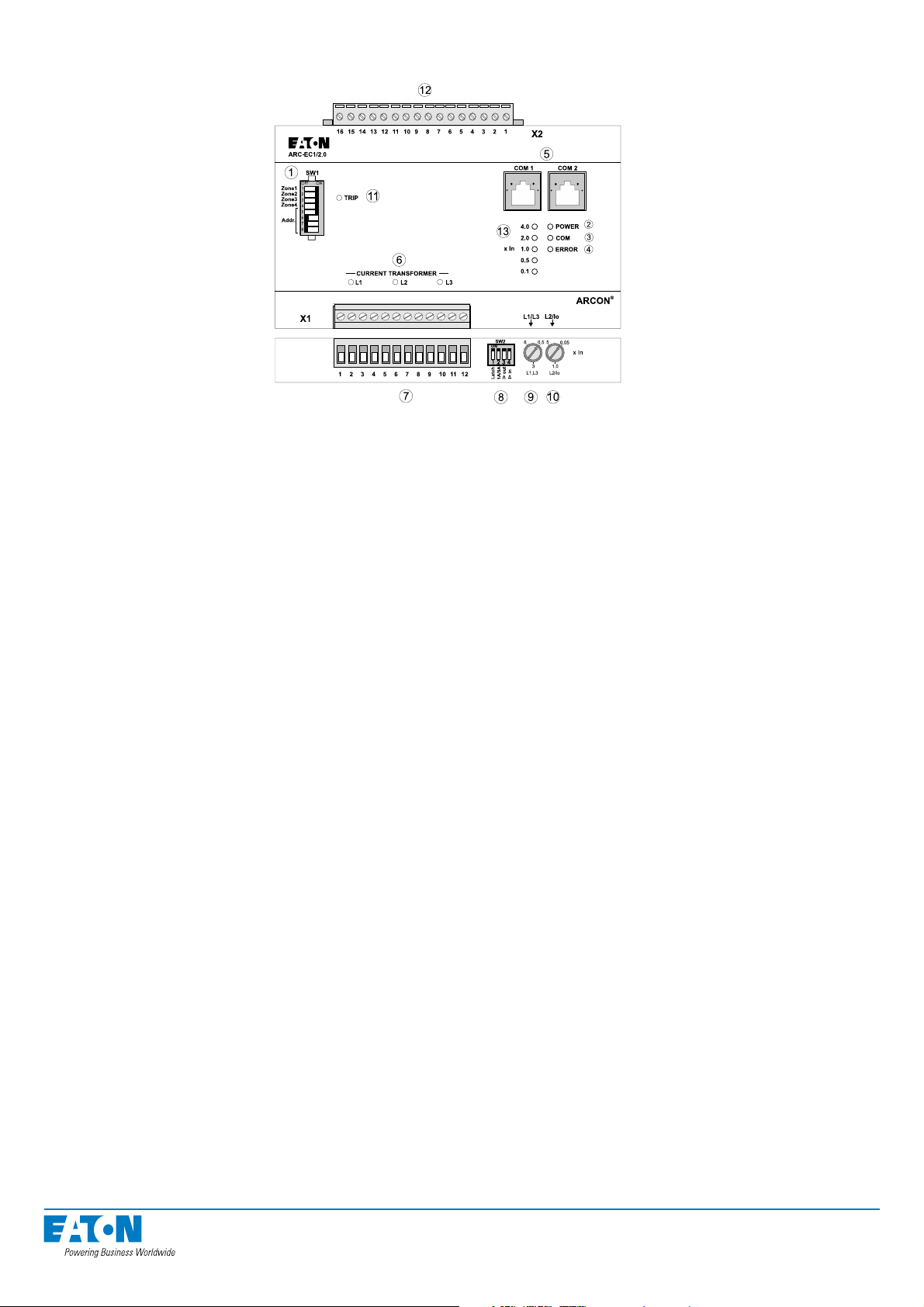
2.2.4. ARC-EC1/2.0
Figure: Current I/O unit ARC-EC1/2.0 front panel
1. Programming switches (factory setting - DIP switches 1...5 in „ON“ position / 6...8
in „OFF“ position
NOTE! The confi guration of the DIP switches must be done properly before operating the system!
2. POWER indicator light, indicates the supply voltages of each component are in order.
3. COM indicator light, lit when the master units and I/O units are communicating.
4. ERROR indicator light, indicates an internal fault detected by the component’s self diagnostics. Such faults include faulty current transformer or phase current unbalance.
5. Connector sockets for the modular cables
6. LED lights indicating that I> stage has started
7. Terminals for three current transformers
8. Current transformer programming switches (factory setting - all DIP switches in „ON“
position
NOTE! The confi guration of the DIP switches must be done properly before operating the system!
9. Overcurrent setting knob (IL1, IL3), setting range 0.5...6*In (factory setting 2.0*In)
10. Overcurrent setting knob (IL2, I0), setting range 0.05...5*In (factory setting 2.0*In)
NOTE! The confi guration of the overcurrent setting must be done properly before operating
the system!
11. I/O unit trip relay activated
12. Terminal block for external communication and BI/O channels and trip signal
13. Indicator LEDs for current setting
19
3. ARCON 2.0 arc protection system operation and troubleshooting
Under normal conditions the arc protection system requires very little attention. The only ser-
vicing measures required in fi eld conditions are scheduled operational tests, the intervals and
scope of which depends on local legislation.
3.1. System status indications
The arc protection system has an extensive indication for different operation modes e.g. sen-
sor activated, overcurrent activated, arc protection tripped, and disturbance. System confi gu-
ration and measurements can also be checked during operation.
ARC-EM/2.0
Figure: ARCON 2.0 in normal mode
In normal mode, only the RUN and POWER indicator lights are lit continuously. The COM in-
dicator light blinks occasionally, indicating communication between units and during installation. The POWER indicator lights of the I/O units must be also permanently on and the COM
indicator light blinks during communication.
20
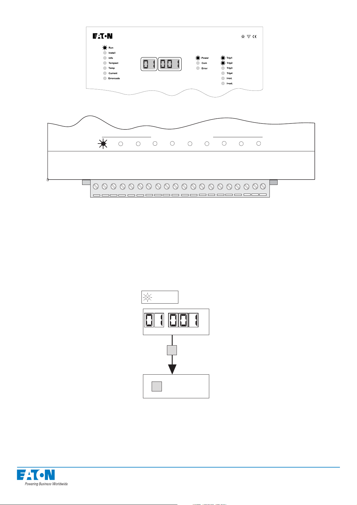
3.1.1. Arc fault
ARC-EM/2.0
Figure: ARCON 2.0 has tripped due to arc fault, light indication I/O unit 1 sensor
SENSOR INPUTS
SENSOR INPUTS
12345678910
12345678910
X1
Figure: ARC-EP10/2.0 indicates light on channel 1
1234567891011121314151617181920
When the arc protection activates due to arc fault, the alarm relay activates and the trip indi-
cator lights indicate the activated output trip relays.
The display at the master unit shows which arc sensor fi rst gave the light information. This
sensor information is only visible in the RUN mode. If several sensors were activated during
the fault, the other activated sensors can be identifi ed from the arc sensor LEDs (I/O units’
indicator lights). The address of an activated sensor is stored in the fault memory, even if activation did not lead to tripping. When the light information is transferred via the BI/O bus, the
source of the light information is not visible on the display.
RUN
I/O UNIT SENSOR
S
CLEARING
E
OF MEMORY
Figure:Reading and resetting the arc fault memory
To reset the arc fault memory, do the following:
• Press the S button to activate the RUN mode.
• When the sensor address blinks on the display, press the E button.
The fault memory resets automatically two hours after activation.
21
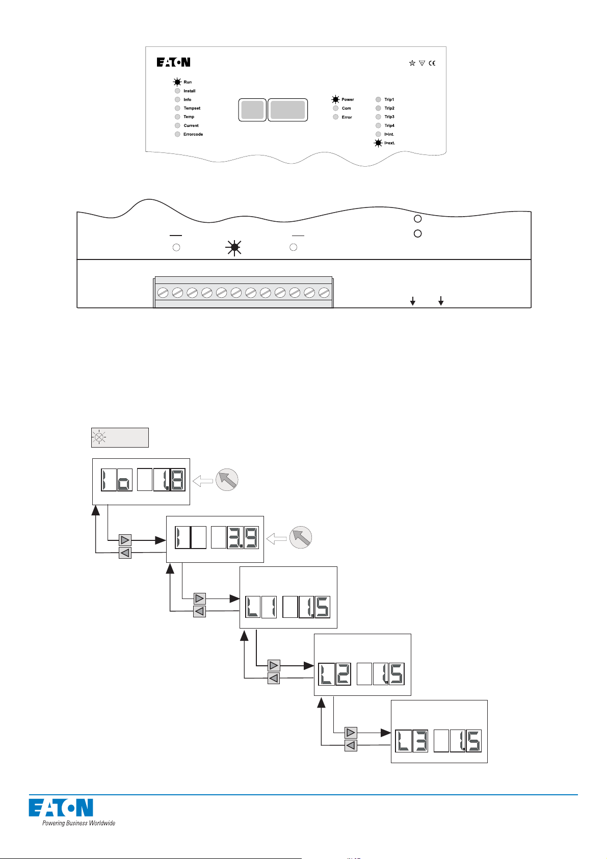
3.1.2. Overcurrent alarm
ARC-EM/2.0
Figure: ARCON 2.0 activated due to overcurrent
CURRENT TRANSFORMER
L1 L2 L3
X1
Figure: ARC-EC1/2.0 indicates overcurrent on channel L2
0.5
0.1
0.1
L1/L3
L2/Io
When any component of the current measuring system detects a current exceeding the setting
value of the unit, it sends current information to all other units. The I>int indicator light is lit when
the master unit measures the overcurrent. If the current information is obtained from outside the
master unit (either through the BI/O bus or from a current I/O unit), the I>ext LED indicator light
is lit. The indicator light of the activated stage is lit in the current I/O unit (ARC-EC1/2.0)
CURRENT
USE THE TRIMMER FOR SET THE LEVEL
OF PICK-UP CURRENT Io/L2
USE THE TRIMMER FOR SET THE LEVEL
OF PICK-UP CURRENT L1/L3
CURRENT IN PHASE 1
CURRENT IN PHASE 2
.
Figure: Reading measured currents in the CURRENT mode
22
CURRENT IN PHASE 3
To read the current values measured by the master unit, do the following:
• Select the CURRENT mode using the up and down arrow keys.
• The earth fault current/phase 2 current setting value appears on the screen (I0).
• Press the right arrow key to view the phase current setting value and instantaneous
values measured in the current measuring channels.
3.1.3. Self-supervision alarm
ARC-EM/2.0
Figure: ARCON 2.0 has detected an internal fault
The system’s self-supervision function continuously monitors the operation of the arc protec-
tion system. The self-supervision function supervises all the components and cables of the
system. When self-supervision detects an internal fault, it activates the SF alarm relay in the
master unit and lights the ERROR indicator LED.
Self-supervision generates a fault code for the detected fault, which is stored in the fault me-
mory of the master unit. The fault memory may contain up to three faults (latest faults).
ERROR CODE
I/O UNIT ERROR CODE
I/O UNIT ERROR CODE
S
CLEARING
E
OF MEMORY
I/O UNIT ERROR CODE
Fault codes can be red only in ERROR CODE mode.
Figure: Reading and resetting the fault memory
To reset the arc fault memory, do the following:
• Press the S button to activate the ERROR CODE mode. The fault code starts blinking.
• Press the E button to erase the latest fault code from the memory. The next fault code,
if any, appears on the screen.
• Once you have acknowledged each fault code separately, the display becomes dark in
the ERROR CODE mode.
NOTE! If the fault that caused the fault code disappears by itself, the fault code in the fault memory is
also erased automatically two hours after the disappearance of the fault.
23
3.1.4. Fault codes
The following table lists the fault codes and gives a brief description of each fault. A more de-
tailed description of the fault and advice on how to locate the faulty component will be given
afterwards.
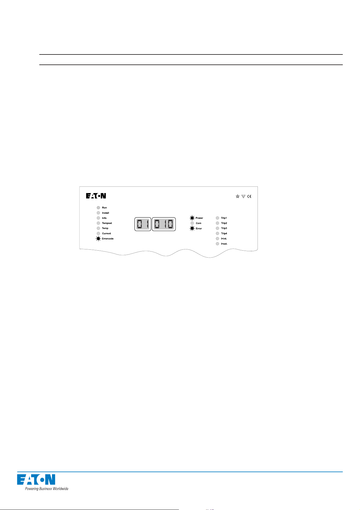
Fault code Fault type Cause
10 System confi guration fault Number of sensors changed
11 Damaged I/O unit Faulty I/O unit in the system
12 Too long BI/O bus activation Faulty arc sensor or too low setting in the
current I/O unit
13 Communication fault Faulty communication channel
14 BI/O channel fault Communication between two master units
interrupted
15 Quenching device fault Communication to quenching
device is interrupted
Table: Self-supervision fault codes
System confi guration fault (fault code 10)
ARC-EM/2.0
Figure: The system indicates a confi guration fault in the I/O unit whose address is 01
This fault code indicates a change in system confi guration.
Potential causes:
1. Sensors have been added to the system after system implementation.
Corrective measures:
• Check the sensor connections of the I/O unit indicated by the fault code and the
programmed confi guration in the INFO mode (see Chapter 3.4.1).
• If the number of sensors in the I/O unit is higher than the number given by the master
unit, re-confi gure the system (see Chapter 3.4).
2. A sensor connected to the system or its wiring is faulty.
Corrective measures:
• Check the confi guration in the INFO mode (see Chapter 3.4.1)
• If the number of sensors in the unit is lower than the number given by the master unit,
check the unit wiring visually and tighten the connections.
• Confi gure the system (see Chapter 3.4)
• If the system still cannot fi nd all the sensors, disconnect the sensor wires one at a time
and confi gure the system after each disconnection.
• Once you have identifi ed the faulty sensor, check the wiring and replace the sensor,
if necessary.
NOTE! The current I/O unit normally indicates three sensors, even if the number of current transfor-
mers connected is only one or two.
24
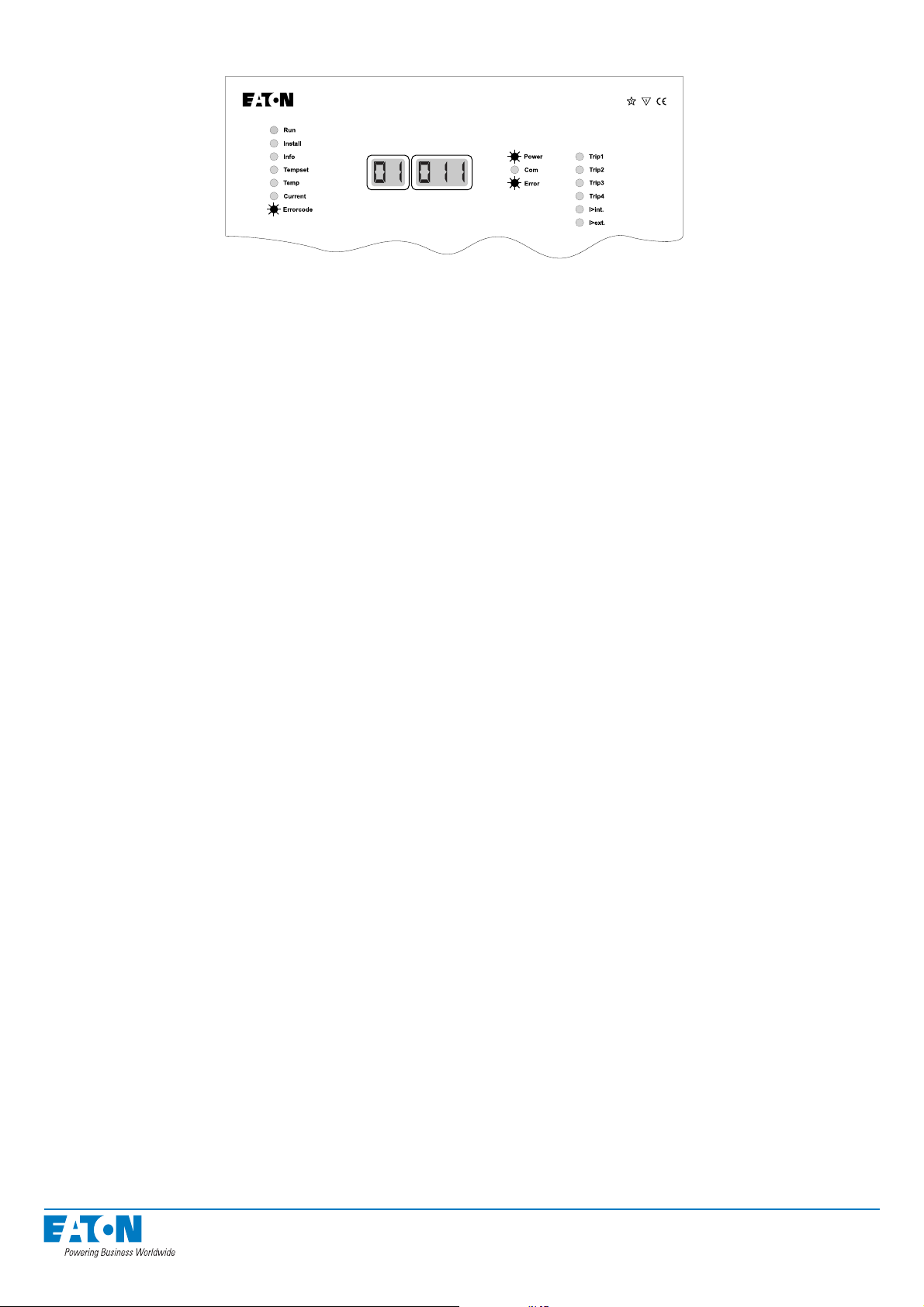
Damaged I/O unit (fault code 11)
ARC-EM/2.0
Figure: The system indicates a fault in the I/O unit whose address is 01.
This fault code indicates a damaged I/O unit.
NOTE! While this fault is activated, no sensor activation connected to the faulty unit will be
transferred to the master unit.
Potential causes:
1. A sensor connected to the unit has remained activated for longer than three seconds.
Corrective measures:
• Check the physical location of the activated sensor.
• Strong, direct light may activate the sensor
• If the arc sensor is not exposed to direct light, remove one of the sensor conductors to
check that the sensor cable is not short-circuited. If the fault disappears, the sensor or
cable is probably damaged. In this case, replace the faulty sensor.
• In the overcurrent unit, check the range of the overcurrent setting and whether the
nominal values of the current transformers’ secondary circuits are compatible.
2. The modular cable connecting the units is loose or faulty.
Corrective measures:
• Check the connection and status of the modular cable connected to the I/O unit
indicated in the fault code.
3. The I/O unit has no supply voltage.
Corrective measures:
• Check whether the POWER indicator light of the I/O unit is lit.
• If the light is not lit, measure if the I/O received a supply voltage of 24 Vdc
(X2-1 +24 Vdc, X2-2 GND). If the voltage supply is in order but the light is not lit,
replace the faulty I/O unit.
• If there is no voltage supply, fi nd out whether it should be supplied from the master unit
or an external voltage supply. Check the voltage of the external voltage supply, if any.
• If the voltage is supplied by the master unit, measure its 24 Vdc supply voltage
(X3-2 +24 Vdc, X3-1 GND). If there is no voltage, replace the master unit.
4. The I/O unit is faulty.
Corrective measures:
• If the TEST/ERROR indication light is permanently lit and no sensor is activated, either
the modular cable (see above) or the I/O unit is faulty. In this case the I/O unit must be
replaced.
25
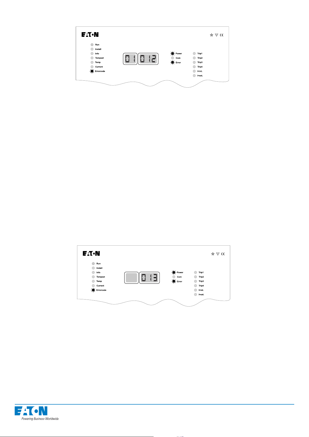
Too long BI/O bus activation (fault code 12)
ARC-EM/2.0
Figure: The system indicates that the BI/O bus has remained activated for longer than three seconds
This fault code indicates that the system’s BI/O bus has remained activated for too long for
normal operation.
Potential causes:
1. A sensor connected to the unit via the BI/O bus has remained activated for longer than
three seconds.
Corrective measures:
• Check the physical location of the activated sensor.
• Strong direct light may activate the sensor
• If the arc sensor is not exposed to direct light, remove one of the sensor conductors to
check that the sensor cable is not short-circuited. If the fault disappears, the sensor or
cable is probably faulty. In this case, replace the faulty sensor.
• In the overcurrent unit, check the range of the overcurrent setting and whether the
check that the sensor cable is not short-circuited. If the fault disappears, the sensor or
cable is probably damaged. In this case, replace the faulty sensor.
Communication fault (fault code 13)
ARC-EM/2.0
Figure: The system indicates a disturbance in the communication between units.
This fault code indicates faulty operation of the system’s communication bus.
Potential causes:
1. The modular cable between units or external wiring has become disconnected or faulty.
Corrective measures:
• Check the connection and status of the modular cable between the units. Maybe there
is a loose contact or damaged cable in the line.
26
 Loading...