

Eaton APS3-300 Installation And Operation Manual

Access Power Solutions
Installation and Operation Guide
(APS3-300 Series)
Issue: IPN 997-00012-48D
Issue Date: November 2012
Refer to the separate SC200 or SC100 system controller handbook for full
details of the system controller operation -
dcpower.eaton.com/Manuals.asp
Eaton Corporation
Telecommunications Power Solutions
dcpower.eaton.com
DCinfo@eaton.com

The product discussed in this literature is subject to terms and conditions outlined in Eaton selling policies. The
sole source governing the rights and remedies of any purchaser of this equipment is the relevant Eaton selling
policy.
No warranties, express or implied, including warranties of fitness for a particular purpose or merchantability, or
warranties arising from course of dealing or usage of trade, are made regarding the information,
recommendations and descriptions contained herein.
In no event will Eaton be responsible to the purchaser or user in contract, in tort (including negligence), strict
liability or otherwise for any special, indirect, incidental or consequential damage or loss whatsoever, including but
not limited to damage or loss of use of equipment, plant or power system, cost of capital, loss of power, additional
expenses in the use of existing power facilities, or claims against the purchaser or user by its customers resulting
from the use of the information, recommendations and descriptions contained herein.
The information contained in this literature is subject to change without notice.
Subject to the right to use its equipment, Eaton Corporation does not convey any right, title or interest in its
intellectual property, including, without limitation, its patents, copyrights and know-how.
No part of this literature may be reproduced or transmitted in any form, by any means or for any purpose other
than the Purchaser’s personal use, without the express written permission of Eaton Corporation.
Eaton®, Matrix, Powerware®, IntergyTM, CellSureTM, SiteSureTM, PowerManagerIITM and DCToolsTM are trade
names, trademarks, and/or service marks of Eaton Corporation or its subsidiaries and affiliates. Unless otherwise
noted, brands, product names, trademarks or registered trademarks are the property of their respective holders.
Copyright © 2007-2012 Eaton Corporation. All Rights Reserved.

About This Guide
Copyright © 2007-2012 Eaton Corporation. All Rights Reserved.
IPN 997-00012-48D November 2012
i
About This Guide
Scope
This guide covers installation, operation and maintenance of Access Power Solutions (APS3-300
Series) dc power systems (APS), controlled by the SC200 or SC100 system controller.
Refer to the separate SC200 or SC100 system controller handbook for full details of the system
controller operation - dcpower.eaton.com/Manuals.asp.
Audience
This guide is intended for use by:
Installers competent in:
installing and commissioning dc power systems
safe working practices for ac and dc powered equipment
the relevant local electrical safety regulations and wiring standards
Operators and maintenance staff competent in:
operation of dc power systems
safe working practices for ac and dc powered equipment
Related Information
SC100 System Controller Operation Handbook* – IPN 997-00012-63
SC200 System Controller Operation Handbook* – IPN 997-00012-50
PowerManagerII Online Help
DCTools Online Help
SiteSure-3G Installation and Operation Guide – IPN 997-00012-51
* Download from: http://dcpower.eaton.com/Manuals.asp.
Reporting Problems with this Guide
Please use this email address to report any problems you find in this guide:
Eaton DC Product Marketing Communications
EMAIL: DCMarketingNZ@eaton.com
For Further Information and Technical Assistance
For further information and technical assistance see Worldwide Support on page 101.

Access Power Solutions Installation and Operation Guide (APS3-300 Series)
ii
Copyright © 2007-2012 Eaton Corporation. All Rights Reserved.
IPN 997-00012-48D November 2012

Table of Contents
Copyright © 2007-2012 Eaton Corporation. All Rights Reserved.
IPN 997-00012-48D November 2012
iii
Table of Contents
About This Guide
Scope ........................................................................................................................................... i
Audience ..................................................................................................................................... i
Related Information .................................................................................................................. i
Reporting Problems with this Guide ...................................................................................... i
For Further Information and Technical Assistance .............................................................. i
Chapter 1 General Description
Overview ................................................................................................................................... 1
Access Power Solutions DC Power Systems ........................................................................ 2
Front View ........................................................................................................................................ 2
Rear View ......................................................................................................................................... 3
Rectifiers .................................................................................................................................... 4
System Controller ..................................................................................................................... 5
SC200 System Controller ................................................................................................................ 5
SC100 System Controller ................................................................................................................ 6
Compatible Software ....................................................................................................................... 6
Input/Output Board ................................................................................................................ 7
Connections ...................................................................................................................................... 8
Other Features .......................................................................................................................... 9
External communications ............................................................................................................... 9
Low Voltage Disconnect Option .................................................................................................... 9
Battery Mid-point Monitoring Option (SC200 only) ................................................................... 9
Battery Time Remaining ............................................................................................................... 10
Chapter 2 Preparation
Overview ................................................................................................................................. 11
Warnings ................................................................................................................................. 12
Inspecting the Equipment and Reporting Damage ........................................................... 14
Chapter 3 Installation
Overview ................................................................................................................................. 15
Installation Tasks .................................................................................................................... 16
Task 1 - Check the AC Supply and Earthing ...................................................................... 16
Task 2 - Prepare APS .............................................................................................................. 19
Task 3 - Connect the AC Supply Cable ............................................................................... 22
Task 4 - Mount the APS in the Rack .................................................................................... 25
Task 5 - Connect the DC Load and Battery Cables ............................................................ 26
Task 6 - Install the Batteries .................................................................................................. 27
Task 7 - Mount the Battery Temperature Sensor ............................................................... 29
Task 8 - Connect External Input/Output Cabling (if required) ....................................... 30
Task 9 - Connect Additional Input/Output (if required - SC200 only) .......................... 31
Task 10 - Connect to the AC Supply Point .......................................................................... 32
Installation Completed .......................................................................................................... 32
Chapter 4 Start-Up
Overview ................................................................................................................................. 33
Start-Up Tasks......................................................................................................................... 34
Task 1 - Inserting the Rectifiers ............................................................................................ 34
Task 2 - Pre-Power-Up Checklist ......................................................................................... 35
Task 3 - Applying AC Power ................................................................................................ 35
Task 4 - Configuring the DC Power System ....................................................................... 36
Task 5 - Applying DC Power to Battery and Load ............................................................ 37
Start-Up Completed ............................................................................................................... 38

Access Power Solutions Installation and Operation Guide (APS3-300 Series)
iv
Copyright © 2007-2012 Eaton Corporation. All Rights Reserved.
IPN 997-00012-48D November 2012
Chapter 5 System Controller
Configuration File ................................................................................................................... 40
Backup and Restore ....................................................................................................................... 40
Starting the SC200 or SC100 .................................................................................................. 41
SC200 ............................................................................................................................................... 41
SC100 ............................................................................................................................................... 41
SC200 or SC100 Operation using the Keypad and Screen ................................................. 42
Keypad Access Security ................................................................................................................ 42
Alarm Indicators ............................................................................................................................ 43
SC200 or SC100 Operation Using a PC/Laptop ................................................................. 44
Using DCTools via USB (SC200 only) ......................................................................................... 44
Using DCTools via RS232 ............................................................................................................. 44
SC200 or SC100 Identity Information ................................................................................... 46
Chapter 6 Maintenance
Overview .................................................................................................................................. 47
Troubleshooting ...................................................................................................................... 48
System Problems ............................................................................................................................ 48
System Controller Problems ......................................................................................................... 51
Replacing or Adding a Rectifier ............................................................................................ 56
Replacing or Adding a Load MCB ....................................................................................... 57
Replacing the System Controller........................................................................................... 58
Replacing the Input/Output Board ...................................................................................... 61
Battery Mid-point Monitoring (String Fail) Alarm (SC200 only) ..................................... 63
Battery Disposal and Recycling............................................................................................. 63
Appendix A Equipment and Tools
Safety Equipment ........................................................................................................................... 65
Essential Tools ................................................................................................................................ 65
Recommended Tools ..................................................................................................................... 65
Spare Parts ............................................................................................................................... 66
Standard Torque Settings ....................................................................................................... 67
Appendix B Specifications
Appendix C Cable Ratings
Appendix D Controller Menus
SC200 Menu ............................................................................................................................. 75
SC100 Menu ............................................................................................................................. 76
Appendix E Connector Pin-outs
System Controller Connector Pin-outs ................................................................................. 77
I/O Board (IOBGP-00, -01) Connector Pin-outs ................................................................. 78
Appendix F Transient Protection
Appendix G Earth Bonding
Appendix H Commissioning
Analog Inputs .......................................................................................................................... 88
System Controls ...................................................................................................................... 90
System Alarms ......................................................................................................................... 93
Digital Inputs ........................................................................................................................... 96
Digital Outputs (Relays) ........................................................................................................ 97
Commissioning Completed ................................................................................................... 97
Equipment Incident Report
Worldwide Support
Index

Chapter 1
General Description
Copyright © 2007-2012 Eaton Corporation. All Rights Reserved.
IPN 997-00012-48D November 2012
1
Topic Page
Access Power Solutions DC Power Systems 2
Rectifiers 4
System Controller 5
Input/Output Board 7
Other Features 9
C h a p t e r 1
General Description
Overview
Access Power Solutions Installation and Operation Guide (APS3-300 Series)
2
Copyright © 2007-2012 Eaton Corporation. All Rights Reserved.
IPN 997-00012-48D November 2012
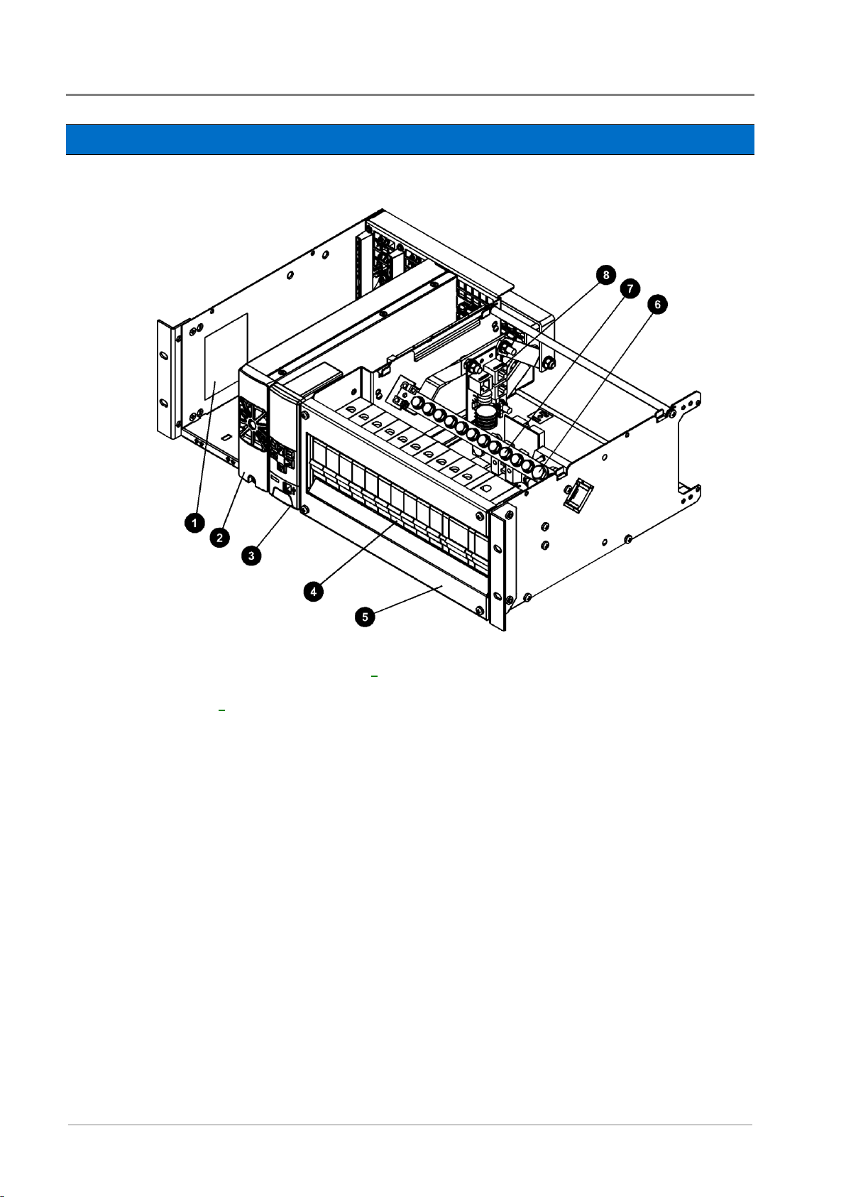
System labels
Rectifier modules (see details on page 4)
SC200 or SC100 system controller (see details
on page 5)
Integrated dc distribution with up to 10 Load and
2 Battery Miniature Circuit Breakers (MCBs)
DC distribution cover
DC common bus battery terminals
DC common bus load terminals
Voltage Feed Module with connector for optional
SiteSure-3G I/O module
Access Power Solutions DC Power Systems
Front View
Optional top cover not shown (IPN: 621-08919-30).
Copyright © 2007-2012 Eaton Corporation. All Rights Reserved.
IPN 997-00012-48D November 2012
3
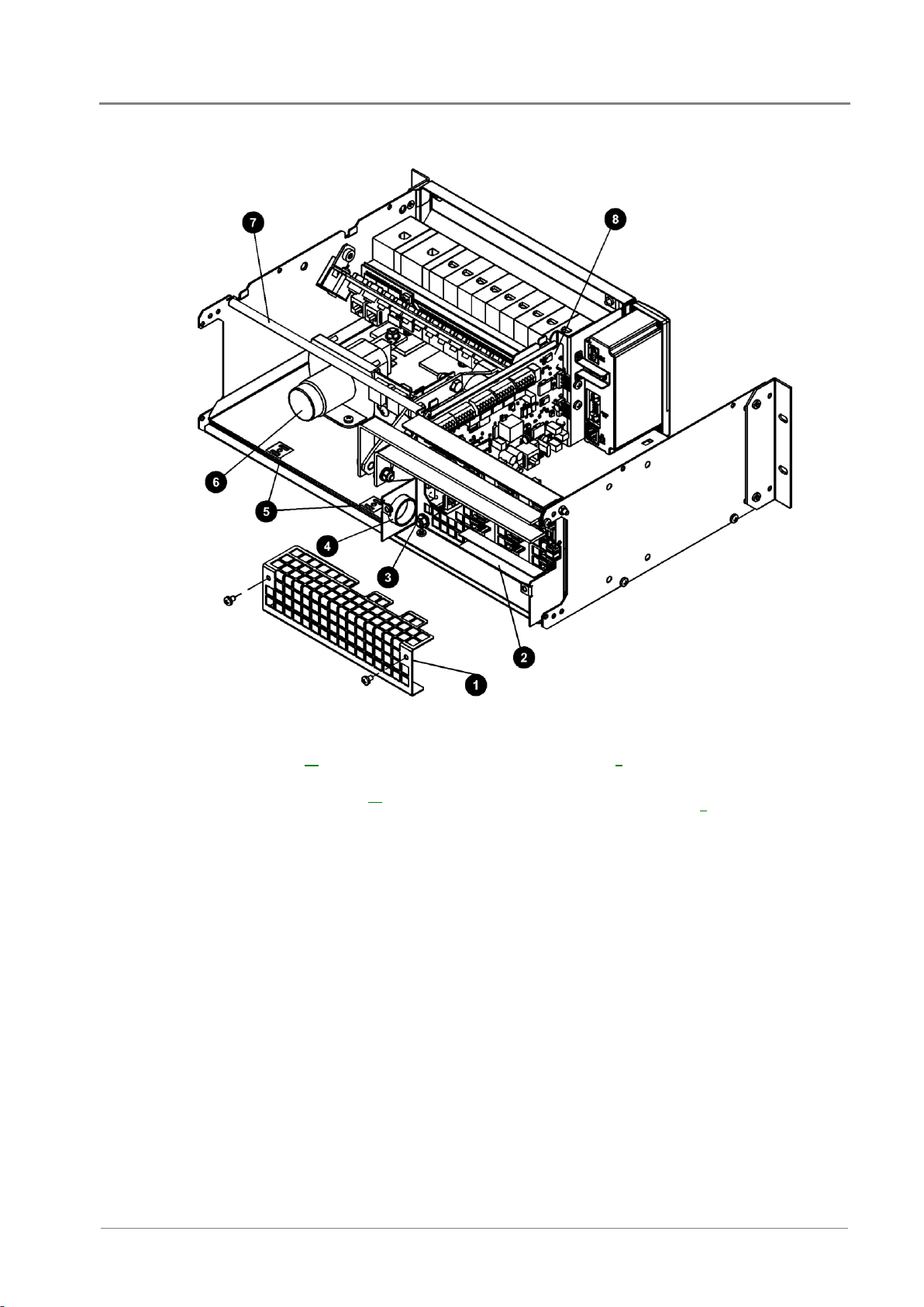
AC terminal cover
AC phase/neutral terminals (see connection
details on page 22)
AC earth conductor connection point (see
connection details on page 22)
AC cable entry gland
Cable tie points
Optional Low Voltage Disconnect (LVD) (see
details on page 9)
Load and battery cable tie rod
I/O Board (see details on page 7)
Rear View
General Description
AC supply cord(s) may be pre-fitted.
Access Power Solutions Installation and Operation Guide (APS3-300 Series)
4
Copyright © 2007-2012 Eaton Corporation. All Rights Reserved.
IPN 997-00012-48D November 2012
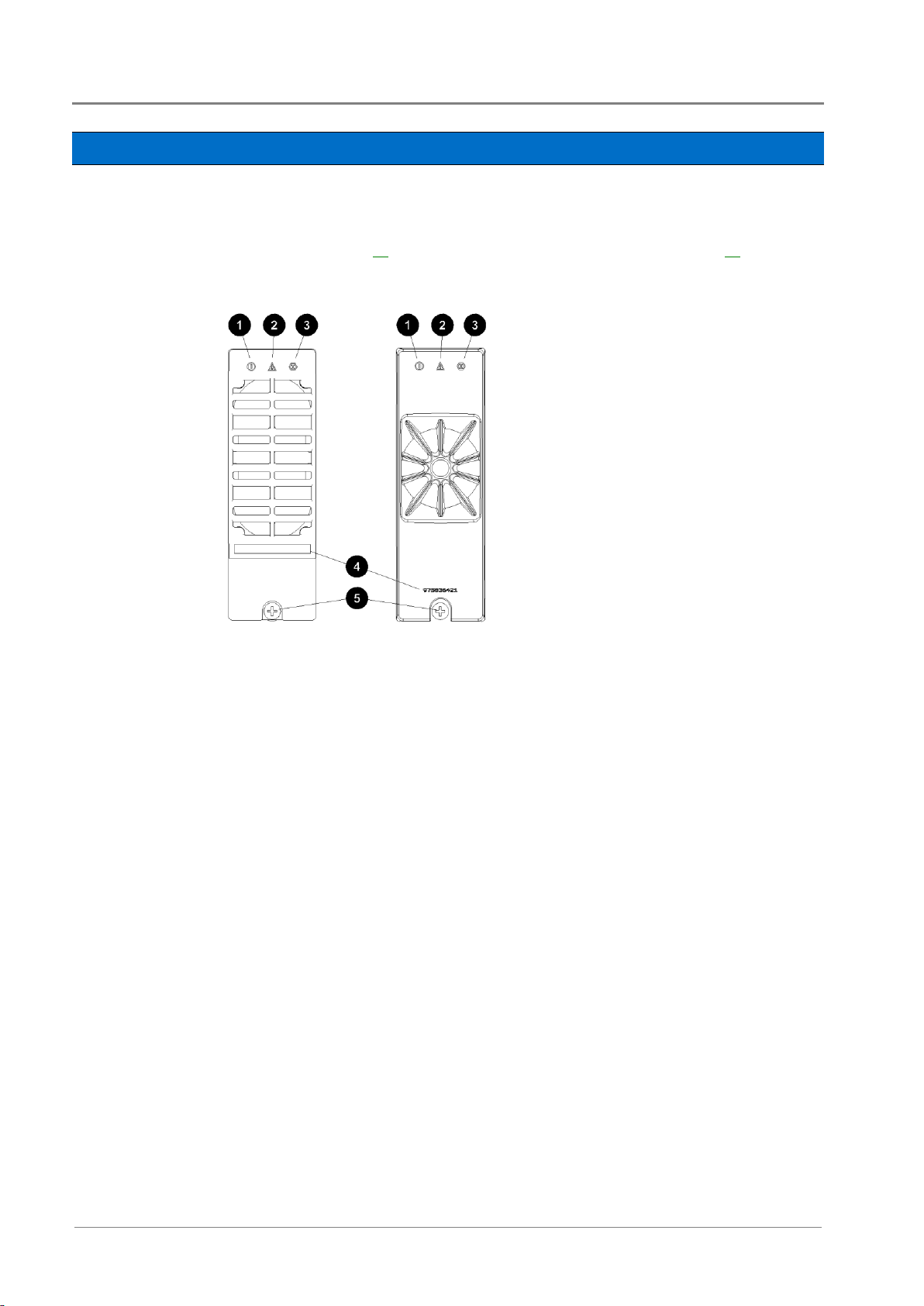
Left: APR24-3G and APR48-3G
Right: APR48-ES
Power On LED (Green)
Minor Alarm LED (Yellow)
Major Alarm LED (Red)
Serial Number
Retaining Screw. Tighten to 1.5Nm
(13.3 inch-pounds).
Rectifiers
Access Power Solutions are fitted with either 48V, 2000W (APR48-ES); 48V, 1800W (APR48-3G);
48V, 900W (EPR48-3G) or 24V, 1440W (APR24-3G) rectifiers. The rectifiers are fan-cooled and
hot-pluggable.
See Specifications on page 69 for further information. See Troubleshooting on page 48 for details of
rectifier alarms.
Copyright © 2007-2012 Eaton Corporation. All Rights Reserved.
IPN 997-00012-48D November 2012
5
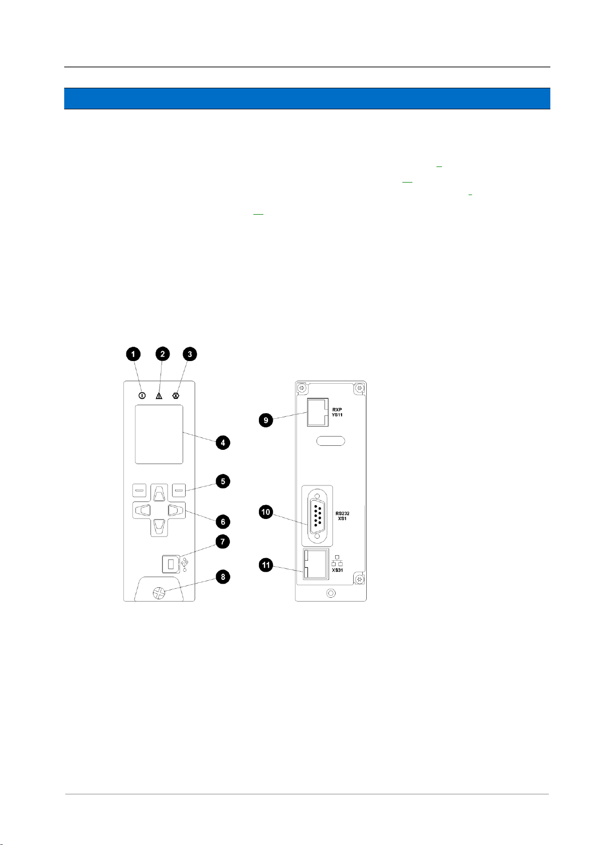
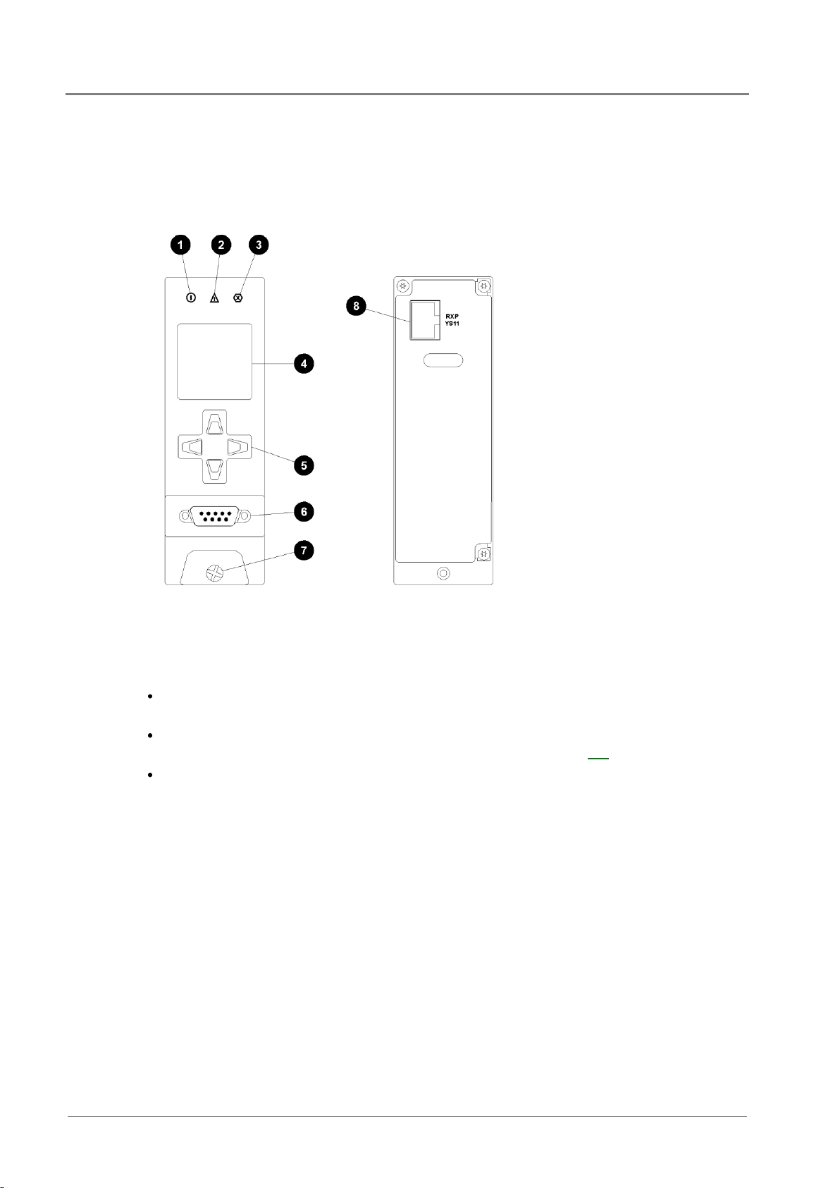
Power on LED (green)
Minor alarm LED (yellow)
Critical/Major alarm LED (red)
Color LCD
Soft keys (2)
Navigation keys (4)
USB 1.1 connector (12Mb/s)
Retaining screw
Power and system
communications connector
RS232 connector
Ethernet connector and
status LEDs
System Controller
The SC200 or SC100 system controller provides control, communications and alarm functions.
The system controller is supplied pre-configured. Configuration changes can be made with the
keypad, or via a PC connected to the USB connector (SC200) or RS232 (SC100) connector. Or
changes can be made remotely (see External Communications on page 9).
For basic operating information see System Controller on page 39. For further details refer to
SC200 System Controller
the System Controller Operation Handbook (see Related Information on page i).
See Troubleshooting on page 48 for details of system controller alarms.
The SC200 system controller is an advanced control and monitoring solution which provides a
full suite of communications options, including built-in Ethernet interface, Web server, and
SNMP agent.
Alarm notifications may be by Email, SNMP traps, SMS text messaging, dial-out to
PowerManagerII remote monitoring software, or relay contact closures.
General Description
Access Power Solutions Installation and Operation Guide (APS3-300 Series)
6
Copyright © 2007-2012 Eaton Corporation. All Rights Reserved.
IPN 997-00012-48D November 2012
Power on LED (green)
Minor alarm LED (yellow)
Critical/Major alarm LED (red)
LCD
Navigation keys (4)
RS232 D9M connector
Retaining screw
Power and system
communications connector
SC100 System Controller
The SC100 system controller is a full-featured control and monitoring solution which provides
alarm notifications via dial-out modem to PowerManagerII remote monitoring software, SMS
text messaging, or by relay contact closures.
Compatible Software
The following software is compatible with the SC200 or SC100 system controller:
DCTools Configuration Software. Latest version is available free from
dcpower.eaton.com/downloads.
PowerManagerII Remote Control and Monitoring Software. Contact your Eaton dc product
supplier for further information (see Worldwide Support on page 101).
Recommended web browsers (SC200 only): Microsoft Internet Explorer 8 or later (IE6 is
compatible but with reduced performance), Mozilla Firefox 3.0 or later.
Copyright © 2007-2012 Eaton Corporation. All Rights Reserved.
IPN 997-00012-48D November 2012
7
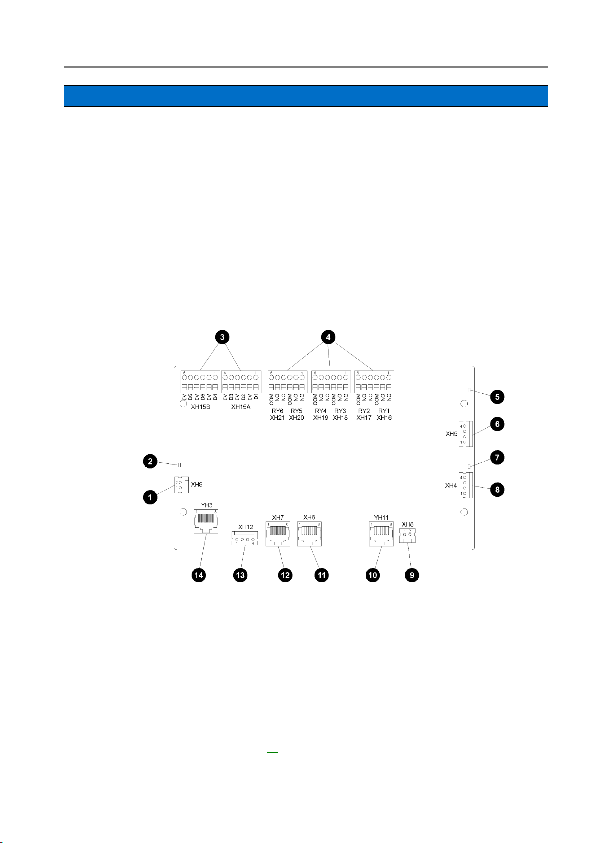
Sensors:
Current - 3, Bus voltage - 1, Temperature - 2, Battery Mid-point - 4
(SC200 only)
Input/Output:
Digital inputs: 4 pre-defined system functions, 6 user-defined
Relay outputs: 6 (one also used as Monitor OK alarm)
LVD contactor outputs: 2
Bus voltage sense input - XH9
Power/Comms OK LED (green)
Digital inputs D1-D6 (6 user defined) - XH15A,
XH15B
Digital (relay) outputs RY1-RY6 (6) - XH16-XH21
LVD contactor 2 status LED (green)
LVD contactor 2 connector - XH5
LVD contactor 1 status LED (green)
LVD contactor 1 connector - XH4
LVD power input connector - XH8
Power and RXP comms input - YH11
Current sense inputs (3) - XH6
Temperature sense inputs (2) - XH7
Battery Mid-point Monitoring sense inputs (SC200
only) - XH12
DC power system digital inputs (4 pre-defined:
Load Fuse Fail, Battery Fuse Fail, AC Distribution
Fan Fail, AC Distribution MOV Fail) - YH3
Input/Output Board
The input/output (I/O) board provides the I/O interfaces and connections for the SC200 or
SC100 system controller.
The I/O board includes a range of sense inputs for dc power system control and monitoring. It
also allows real time data collection from building services and other external devices, and relay
outputs for alarm signals or control of external devices.
The I/O functions are:
For input and output specifications see details on page 70. For connector pin-outs see details on
page 78.
General Description
See Troubleshooting on page 48 for details of I/O board LED signals.
Access Power Solutions Installation and Operation Guide (APS3-300 Series)
8
Copyright © 2007-2012 Eaton Corporation. All Rights Reserved.
IPN 997-00012-48D November 2012
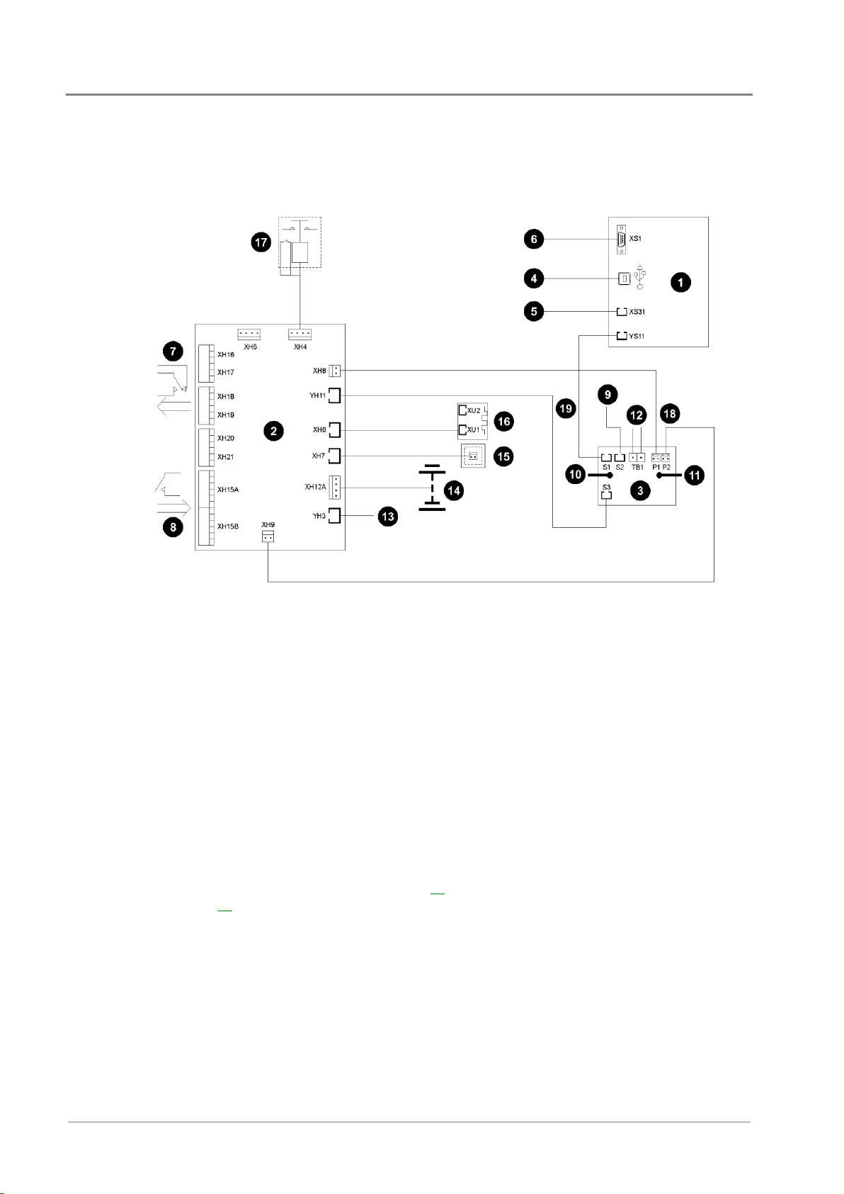
SC200 or SC100 system controller
I/O board
Voltage feed module
USB communications (SC200 only)
Ethernet communications (SC200 only)
RS232 communications
Digital relay outputs (6) to external devices
and/or alarm indication system
Digital inputs (6) from external voltage-free
switches or relay contacts
Connection to additional I/O board(s) and/or
SiteSure-3G I/O module(s) (SC200 only)
Connection to dc common bus
Connection to dc live bus
Communications to rectifiers
DC power system digital inputs (Load Fuse Fail,
Battery Fuse Fail, AC Distribution Fan Fail, AC
Distribution MOV Fail)
Connections to battery mid-points (4)
(SC200 only)
Connection to temperature sensors (2)
Connection to current sensors (3)
Optional LVD contactor and auxiliary switch
Bus voltage sense and LVD power connections
I/O and system controller power and RXP comms
connection
Connections
The following diagram shows the connections between the SC200 or SC100, the I/O board, the
other dc power system components and external devices.
For connector pin-outs see details on page 78. For input and output specifications see details on
page 69.

Copyright © 2007-2012 Eaton Corporation. All Rights Reserved.
IPN 997-00012-48D November 2012
9
Communications options
SC200
SC100
Communication with DCTools via USB
-
Communication with DCTools or PowerManagerII via RS232
Communication with DCTools or PowerManagerII via
an external PSTN or GSM modem (dial-in and dial-out on alarm)
Communication with DCTools or PowerManagerII via Ethernet
-
Communication with web browser software via an IP network
-
Communication with a Network Management System (NMS) using
SNMP
-
Communication with a Building Management System (BMS) using
Modbus
-
Alarm and status messages to GSM Short Messaging Service (SMS)
text capable cell phones
Communication with an alarm management system using
voltage-free relay contacts (on an IOBGP I/O board)
Other Features
External communications
Refer to the system controller handbook for information on these communications options.
General Description
Low Voltage Disconnect Option
An optional Low Voltage Disconnect (LVD) is available for the Access Power Solutions
(APS3-300 Series). See the diagram on page 3 for location. This is connected as a battery
disconnect.
For information on operation see Low Voltage Disconnect (LVD) in the System Controller
Operation Handbook.
Battery Mid-point Monitoring Option (SC200 only)
Battery Mid-point Monitoring provides a cost-effective method for the early detection of
internal battery faults. The voltages of the two halves of a battery string are measured and the
system controller generates an alarm signal if a voltage imbalance is detected.
A voltage imbalance is an indication that one or more cells has an internal fault. Further
investigation can then isolate the faulty cell(s) and action can be taken to correct the problem
and prevent a total battery failure.
To connect Battery Mid-point Monitoring see details on page 28. If a String Fail alarm is
generated see Troubleshooting on page 48.
To ensure reliable operation Mid-point Monitoring operates only when the battery is in float
charge and after a configurable lockout period since the last battery discharge, Fast Charge,
Equalize or Battery Test.

Access Power Solutions Installation and Operation Guide (APS3-300 Series)
10
Copyright © 2007-2012 Eaton Corporation. All Rights Reserved.
IPN 997-00012-48D November 2012
Battery Time Remaining
The SC200 or SC100 obtains characterization data from either periodic battery discharges
(SC100) or every full battery discharge (SC200), to a specified end voltage.
During a battery discharge, the SC200 or SC100 uses this characterization data to calculate an
estimated time until the battery will reach the specified end voltage.
If a battery disconnect LVD is fitted then the end voltage will usually be the voltage at which the
LVD disconnects the battery.
Battery Time Remaining is designed for a constant power load. The accuracy of the time
remaining calculation will be reduced if the dc power system is connected to a predominantly
resistive (constant current) load.
The time remaining calculation will not be correct if a non-essential load is disconnected during
the battery discharge.
For details refer to Battery Time Remaining in the SC200 or SC100 System Controller Operation
Handbook (see Related Information on page i).

Chapter 2
Preparation
Copyright © 2007-2012 Eaton Corporation. All Rights Reserved.
IPN 997-00012-48D November 2012
11
Topic Page
Warnings 12
Inspecting the Equipment and Reporting Damage 14
C h a p t e r 2
Preparation
Overview

Access Power Solutions Installation and Operation Guide (APS3-300 Series)
12
Copyright © 2007-2012 Eaton Corporation. All Rights Reserved.
IPN 997-00012-48D November 2012
Electrical Safety
Access Power Solutions (APS3-300 Series) dc power systems must be mounted in an enclosed cabinet that
meets safety and fire enclosure requirements as specified in AS/NZS 60950.1 and EN 60950-1.
The dc power system may be powered from multiple ac sources. All ac sources must be isolated before
internally servicing the equipment.
The dc power system MCBs are not a disconnect device. The APS dc power system must be connected to
a suitable upstream ac supply disconnect device such as Miniature Circuit Breaker(s) (MCB) or fuses.
This device must isolate both the phase and neutral conductors in single-phase and three-phase
connections, unless the neutral conductor is clearly identified.
If the dc power system is to be installed in a location where the ambient temperature may rise above 50ºC
(122ºF), then 90°C rated cable rated cable must be used for all connections.
The dc power system is not compatible with IT (Impedance Terra) ac power distribution topologies. For
advice see Worldwide Support on page 101.
A registered electrician (or suitably qualified person) must check the integrity of the installed cabling,
BEFORE the dc power system is powered up.
Tasks must be performed in the sequence documented in this guide.
Location and Environment
An APS dc power system must be installed in a restricted access location.
For ease of access and to maintain optimum system cooling observe the clearances stated on page 25.
Dust build-up within the dc power system may cause premature failure. In dusty environments filter the
ventilation air entering the equipment room. Ensure regular cleaning of the air filters.
Do not allow water or any foreign object to enter the dc power system. Do not place objects containing
liquid on top of or near the unit.
Flooded cell and VRLA lead acid batteries can emit explosive gases and must be installed with adequate
ventilation. Refer to the battery manufacturer or supplier for advice on minimum ventilation levels.
Reverse Polarity
Always check that the battery cables have been terminated to the correct system polarity BEFORE
connecting the batteries or closing the battery disconnect device. Connecting batteries to the dc power
system with incorrect system polarity will damage the rectifiers and void all warranty claims.
Hazardous Energy Levels
Rectifiers and batteries contain hazardous energy levels. Only personnel trained and experienced in dc
power systems are to service/maintain this equipment.
Always use insulated tools.
Do not short-circuit the live and common bus bars or cables.
Warnings
This section contains important warnings. Read these warnings before installing or operating an
Eaton Access Power Solutions dc power system.

Preparation
Copyright © 2007-2012 Eaton Corporation. All Rights Reserved.
IPN 997-00012-48D November 2012
13
Batteries
The plastic cases of batteries installed in Eaton dc power system racks must have a flammability rating of
UL 94-V2 or better.
Flooded cell and VRLA lead acid batteries can emit explosive gases and must be installed with adequate
ventilation. Refer to the battery manufacturer or supplier for advice on minimum ventilation levels.
Do not wear a synthetic dust-coat or overalls. Synthetic fabrics can hold static electric charges that create
sparks during discharge.
Remove rings, wristwatch and other metal jewelry that might be exposed to battery terminals, before
installing batteries.
Batteries are powerful sources of energy and present a potential electrical shock and energy hazard. The
energy hazard is always present, even if the batteries are not connected. Avoid short circuiting terminals
of opposite polarity.
Always use insulated tools.
Do not place tools, loose cables or metal objects (such as interconnecting bars) on top of batteries.
Do not drop tools, loose cables or metal objects onto intercell connections or terminals of opposite
polarity.
Only terminate cables and interconnecting bars after confirming that the termination will not create a
short circuit.
Always tighten battery terminal bolts according to the battery manufacturer’s specification. Failing to do
so can cause erratic battery performance, possible damage to the battery, and/or personal injury.
There is a risk of electric shock or explosion if a battery is replaced by an incorrect type.
Dispose of batteries according to the instructions on page 63.
Rectifiers
Only operate the rectifiers when the surrounding area is clean and dust free.
To reduce the risk of electric shock and maintain optimum system cooling, always cover empty rectifier
slots with blanking panels.
To avoid electrical shock, do not place hands inside the rectifier magazine.
Rectifier cases may exceed 100ºC (212ºF), especially after prolonged operation. Use suitable gloves when
removing a rectifier from the magazine.
Do not attempt to disassemble faulty rectifiers. Return them (in their original packaging) with a
completed Equipment Incident Report on page 99.
Ensure that any upstream Residual Current Devices (RCDs) are appropriately rated for the rectifiers'
maximum earth leakage current (see Specifications on page 69 for value).
DC Distribution(s)
The dc common bus of the dc power system can be connected to earth (ground). If this connection is
made all of the following conditions must be met:
Your equipment and the dc power system must be located within the same premises.
No switching or disconnecting devices are allowed in the conductor between the dc common line
and the point of connection to the earth electrode conductor.
See Connecting the Output to Earth on page 19 for further information.
For installations in the United States, Listed compression connectors must be used to terminate Listed
field-wired conductors where required. For all installations, use the appropriate connector for the
conductor size as specified by the connector manufacturer. And use only the connector manufacturer's
recommended tooling or tooling approved for that connector.
Follow all applicable local and national rules and regulations when making field connections.
Tighten all electrical connections to the torques stated in this guide or on the manufacturer's label.

Access Power Solutions Installation and Operation Guide (APS3-300 Series)
14
Copyright © 2007-2012 Eaton Corporation. All Rights Reserved.
IPN 997-00012-48D November 2012
Servicing and Maintenance
The APS contains hazardous voltages and hazardous energy levels. Before undertaking any maintenance
task refer to the Warnings on page 12.
If a maintenance task must be performed on a "live" system then take all necessary precautions to avoid
short-circuits or disconnection of the load equipment, and follow any "live-working" instructions
applicable to the site.
Only perform the maintenance tasks described in the Maintenance chapter. All other tasks are classified
as Servicing. Servicing must only be performed according to specific instructions and only by personnel
authorized by Eaton. This includes disassembly and/or servicing of any modules.
For further information on Servicing contact your local Eaton dc product supplier, or refer to the contact
details on page 101.
EMC Compliance
This dc power system may be used in close proximity to other electronic equipment, provided
installation is carried out according to instructions in this guide. However, proper installation and
compliance with EMC standards does not guarantee that the dc power system will not respond to
electromagnetic disturbances, or will not cause interference to other equipment in a particular
installation.
In a domestic environment this product may cause radio interference in which case the user may be
required to take adequate measures.
This equipment generates, uses, and can radiate radio frequency energy and, if not installed and used in
accordance with the instructions, may cause harmful interference to radio communications. However,
there is no guarantee that the interference will not occur in a particular installation. If this equipment
does cause harmful interference to radio or television reception, which can be determined by turning the
equipment off and on, the user is encouraged to try to correct the interference by one or more of the
following measures:
Reorient or relocate the receiving antenna.
Increase the separation between the equipment and receiver.
Connect the equipment into an outlet on a circuit different from that to which the receiver is
connected.
Consult the dealer or an experienced radio/TV technician for help.
Inspecting the Equipment and Reporting Damage
Unpack the equipment and inspect it carefully for possible damage that may have occurred
while in transit. Do not use any damaged equipment.
Report any damage immediately, using a completed Equipment Incident Report on page 99.
Keep the original packaging to use if any item needs to be returned for replacement or repair.

Chapter 3
Installation
Copyright © 2007-2012 Eaton Corporation. All Rights Reserved.
IPN 997-00012-48D November 2012
15
Topic Page
Installation Tasks 16
Task 1 - Check the AC Supply and Earthing 16
Task 2 - Prepare APS 19
Task 3 - Connect the AC Supply Cable 22
Task 4 - Mount the APS in the Rack 25
Task 5 - Connect the DC Load and Battery Cables 26
Task 6 - Install the Batteries 27
Task 7 - Mount the Battery Temperature Sensor 29
Task 8 - Connect External Input/Output Cabling (if required) 30
Task 9 - Connect Additional Input/Output (if required - SC200 only) 31
Task 10 - Connect to the AC Supply Point 32
Installation Completed 32
C h a p t e r 3
Installation
Overview

Access Power Solutions Installation and Operation Guide (APS3-300 Series)
16
Copyright © 2007-2012 Eaton Corporation. All Rights Reserved.
IPN 997-00012-48D November 2012
Task
Description
Reference
1
Check the AC Supply and Earthing
See details on page 16
2
Prepare the APS
See details on page 19
3
Connect the AC Supply Cable
See details on page 22
4
Mount the APS in the Rack
See details on page 25
5
Connect the dc Load and Battery Cables
See details on page 26
6
Install the Batteries
See details on page 27
7
Mount the Battery Temperature Sensor
See details on page 29
8
Connect External Input/Output Cabling (if required)
See details on page 30
9
Connect Additional Input/Output (if required - SC200
only)
See details on page 31
10
Connect to the AC Supply Point
See details on page 32
1 Confirm that there is a transient protection plan (compliant with IEC 61643-12)
for the site.
For more information see Transient Protection on page 81.
2 If necessary, install suitable transient protection.
Installation Tasks
Before starting the installation, review the following information:
Required Equipment and Tools on page 65
Warnings and Cautions on page 12
Inspecting the Equipment and Reporting Damage on page 14
Complete the Installation tasks in the following order:
For installation of external communications see Communications Options in the System
Controller Operation Handbook.
Task 1 - Check the AC Supply and Earthing
It is important that the ac supply for the Access Power Solutions dc power system includes the
correct levels of protection.
Step 1 - Check transient voltage protection at the site
Installation
Copyright © 2007-2012 Eaton Corporation. All Rights Reserved.
IPN 997-00012-48D November 2012
17
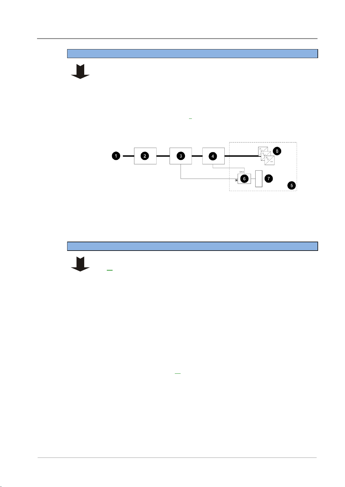
1 Check if the ac voltage is expected to exceed 275V (L-N).
2 If so, then it is strongly recommended that an external high voltage protection
unit (HVPU) be installed. This will automatically disconnect the ac at high
voltage and reconnect it at normal voltage.
3 Install the HVPU as in the following diagram.
4 Connect the High VAC alarm output to one of the Digital Inputs on the I/O
board (see the diagram on page 7 for location).
The High VAC alarm signal lines must be isolated from the ac supply by a
voltage-free relay contact.
AC supply
Primary transient protection devices
High voltage protection unit with alarm output
Secondary transient protection devices
(MOVs)
dc power system
I/O board
SC200 or SC100 system controller
Rectifiers
1 Check the type of ac supply. Only the types of ac supply listed in Task 3 on page
22 are suitable for the APS.
Only use a two-phase or three-phase (L-L) ac supply if referenced to earth, or a
protection system is in place so that the phase-earth voltage cannot exceed the
rating of the rectifier.
2 Check that the APS will be connected to a suitable upstream ac disconnect
device such as Miniature Circuit Breaker(s) (MCB) or fuses.
3 Check the disconnect device will isolate both the phase and neutral conductors
in single-phase and three-phase connections, unless the neutral conductor is
clearly identified.
4 Check that any Residual Current Devices (RCD) upstream of the APS are rated
for the maximum earth leakage current of the rectifiers. If necessary, install
higher rated RCD(s).
The maximum earth leakage current of Access Power Rectifiers is given in the
Specifications on page 69.
Step 2 - Check high ac voltage protection at the site
Step 3 - Check the type of ac supply, disconnect device and RCDs
Access Power Solutions Installation and Operation Guide (APS3-300 Series)
18
Copyright © 2007-2012 Eaton Corporation. All Rights Reserved.
IPN 997-00012-48D November 2012
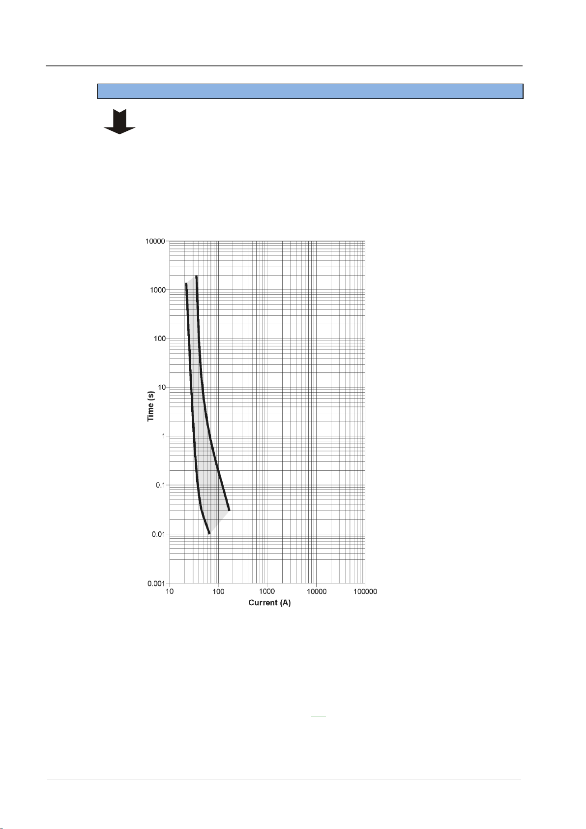
Each rectifier has two internal fast-acting fuses. Under certain internal fault
conditions these fuses will blow.
If there is insufficient discrimination between these fuses and any upstream ac
supply-disconnect device then the upstream ac supply-disconnect device will
operate before a rectifier fuse blows. This will disconnect the ac supply to all
rectifiers.
1 Check the time-current (tripping) curve(s) of all ac supply-disconnect device(s)
upstream of the APS with the following curve for the rectifier fuses.
Refer to the manufacturer's data for tripping curves.
Time-Current Curve
(minimum and
maximum) for rectifier
internal fuses (IEC
60127-2).
Source: Schurter SP 5x20
Pigtail data sheet.
2 No action is required if the time-current curves of the upstream ac
supply-disconnect devices are entirely to the right of the curves for the rectifier
fuses.
3 If the curve of an upstream ac supply-disconnect device crosses the curve for the
rectifier fuse there may not be adequate discrimination.
If necessary, replace the upstream ac supply-disconnect device to achieve
adequate discrimination. Or, contact your Eaton dc product supplier for advice
(see Worldwide Support on page 101).
Step 4 - Check ac discrimination

Installation
Copyright © 2007-2012 Eaton Corporation. All Rights Reserved.
IPN 997-00012-48D November 2012
19
Confirm that all earths are brought together at one "star" point so that surge currents
cannot flow in "earth loops" and create large voltages.
For more information see Transient Protection on page 81.
Ignore this Step if the system controller is already fitted.
1 Connect the power/communications cable from the APS to the RJ45 socket YS11
(RXP) socket on the back of the system controller.
2 Fit the system controller into the APS and tighten the retaining screw.
See the diagram on page 2 for position of system controller.
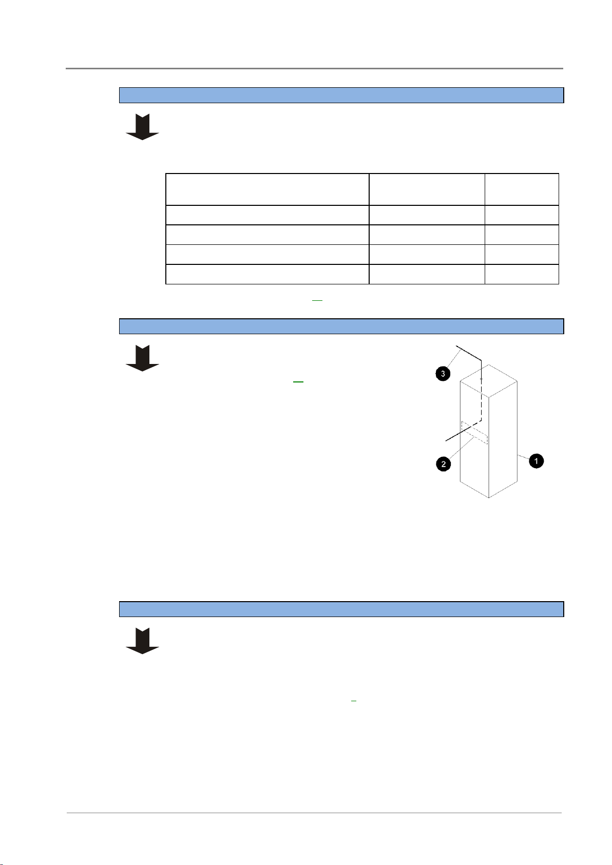
The APS can be configured for either positive earth or negative earth operation.
1 Remove top cover if fitted.
2 Check the polarity label on the dc common bus bar(s).
(+) on the common bar(s) indicates positive earth. (-) indicates negative earth.
3 If the polarity of the APS matches the equipment at the site then no further action
is required.
4 If the polarity of the APS is not correct for the equipment to be powered then
contact your Eaton dc product supplier for advice (see Worldwide Support on
page 101).
APSs are pre-assembled with 19-inch rack-mounting brackets as shown in the
following diagram. If required, the brackets can be moved to alternative positions to
reduce the effective depth of the unit.
Rack-mounting brackets are also available for use in 23-inch wide racks.
1 Remove top cover if fitted.
2 Undo the two screws holding each bracket.
3 Refit the brackets at the required location. Tighten the screws.
Step 5 - Check the earthing arrangements at the site
Procedure complete
Task 2 - Prepare APS
Step 1 - Fit the system controller (if required)
Step 2 - Check polarity
Step 3 - Check position of mounting brackets
Access Power Solutions Installation and Operation Guide (APS3-300 Series)
20
Copyright © 2007-2012 Eaton Corporation. All Rights Reserved.
IPN 997-00012-48D November 2012
Rack-mounting bracket (available for 19-inch
and 23-inch wide racks)
Alternative bracket mounting positions
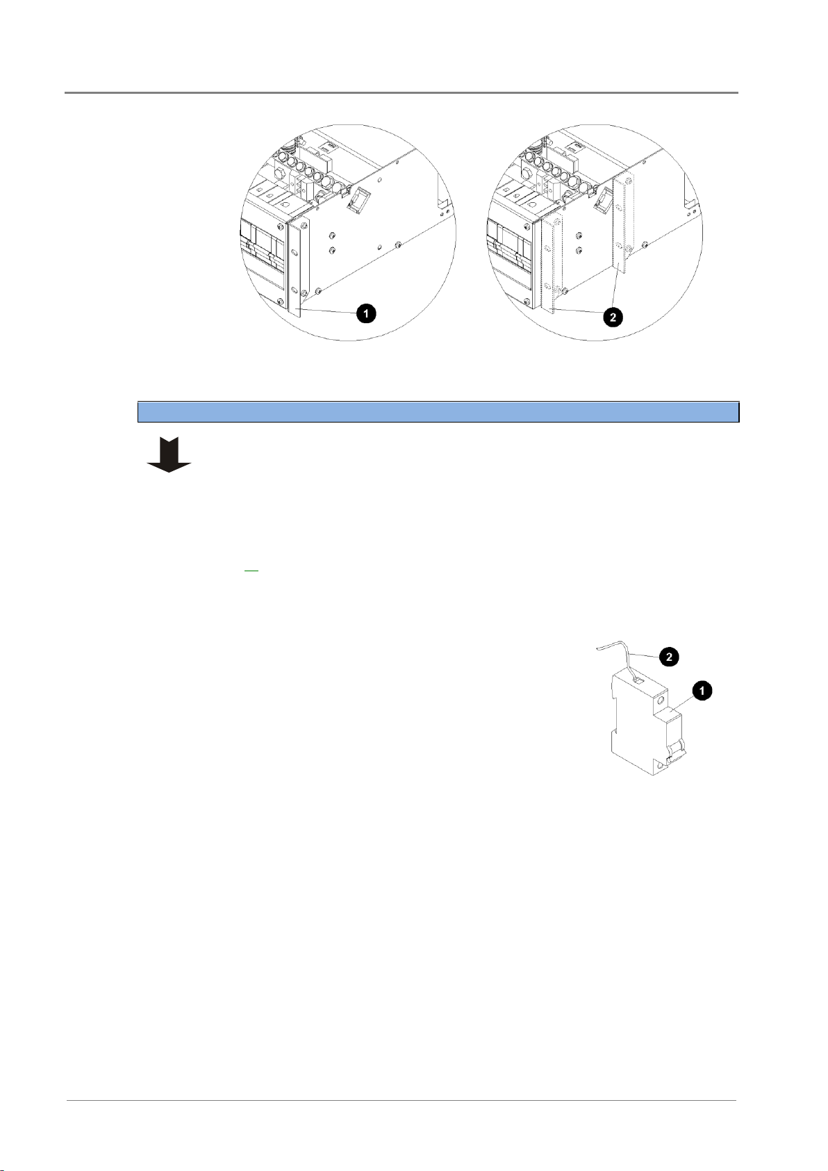
Ignore this Step if the load MCBs are already fitted.
The current rating of the MCBs must be derated to 75%.
The APS can use either Chint or Schneider circuit breakers. However, Chint and
Schneider circuit breakers are not interchangeable. When replacing existing circuit
breakers or fitting new ones, use the type that is already in use (see Spare Parts on page
66 for ordering details).
1 Remove the dc distribution front cover and top cover (if fitted).
2 Fit the load MCBs onto the load tooth-comb bus (start at the right-hand end) and
clip onto the DIN rail. Tighten the bottom MCB terminals.
3 Cut the load fuse fail detect wires (from the fuse
fail alarm board on the APS) to the correct length to
reach the MCBs.
There is one load fuse fail detect wire for each load
MCB. These wires are thinner than the battery
fuse fail detect wires.
4 Connect the wires to the top terminals of the MCBs
and tighten terminal to hold the wire in place.
5 Fit MCB blanks to cover any unused positions.
6 Switch OFF all MCBs.
Load MCB
Load fuse fail detect wire
from fuse fail alarm board.
Step 4 - Install Load circuit breakers (if required)
Installation
Copyright © 2007-2012 Eaton Corporation. All Rights Reserved.
IPN 997-00012-48D November 2012
21
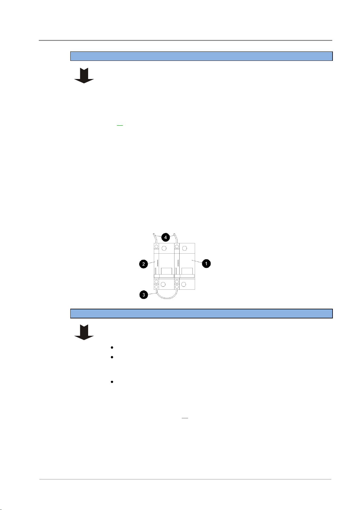
Ignore this Step if the Battery MCBs are already fitted.
The current rating of the MCBs must be derated to 75%.
The APS can use either Chint or Schneider circuit breakers. However, Chint and
Schneider circuit breakers are not interchangeable. When replacing existing circuit
breakers or fitting new ones, use the type that is already in use (see Spare Parts on page
66 for ordering details).
1 Place the battery MCBs side-by-side (see following diagram).
2 Use the battery fuse fail detect loop wire to connect the auxiliary switches in
series.
Use the auxiliary switch terminals that will be closed when the MCB is ON.
3 Fit the MCBs onto the battery tooth-comb bus (at the right hand end) and clip
onto the DIN rail.
4 Tighten the bottom MCB terminals.
5 Connect the battery fuse fail detect wires to the MCB auxiliary switches (see
following diagram). Tighten the terminals.
6 Fit MCB blanks to cover any unused positions.
7 Switch OFF all MCBs.
Battery MCBs (front view)
Auxiliary switches
Fuse fail detect loop wire
Battery fuse fail detect wires
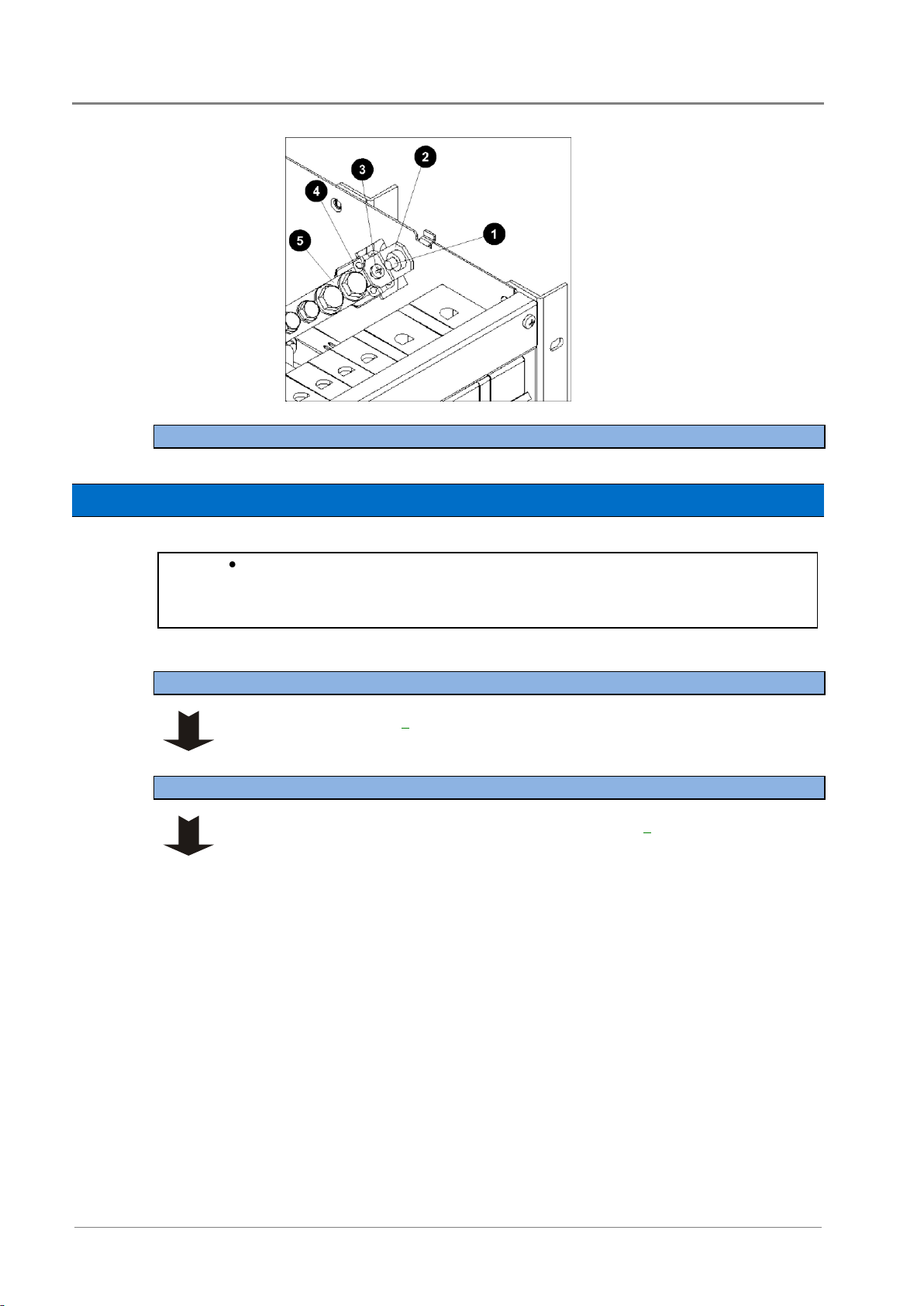
There are two options: ac and dc earths bonded or separated.
1 Check if the APS ac and dc earths are bonded:
Remove top cover (if fitted).
If the ac-dc earth link busbar (at one end of the dc common bar) is fitted (see
following diagram) then the ac and dc earths are bonded. This is the
recommended, factory standard arrangement.
If the busbar is not fitted then the ac and dc earths are separated.
2 If the arrangement of the ac and dc earths is as required, no further action is
required.
3 If the arrangement of the ac and dc earths is not as required, follow the procedure
in Earth Bonding on page 85.
Step 5 - Install Battery MCBs (if required)
Step 6 - Check if the APS ac and dc earths are bonded
Access Power Solutions Installation and Operation Guide (APS3-300 Series)
22
Copyright © 2007-2012 Eaton Corporation. All Rights Reserved.
IPN 997-00012-48D November 2012
Busbar chassis screw
Busbar
Busbar stand-off screw
Stand-off
DC common bar
If the APS dc power system is to be installed in a location where the ambient temperature
may rise above 50º (122ºF), then 90°C rated cable rated cable must be used for the ac
connections.
See the diagram on page 2 for location of ac rating label.
1 Remove the ac terminal cover (see the diagram on page 3).
2 If ac MCB(s) fitted, remove the distribution front cover and remove the top
cover (if fitted).
Procedure complete
Task 3 - Connect the AC Supply Cable
If the APS has pre-fitted ac cord(s) then ignore this task.
Step 1 - Check ac rating of the APS
Step 2 - Remove covers
Installation
Copyright © 2007-2012 Eaton Corporation. All Rights Reserved.
IPN 997-00012-48D November 2012
23
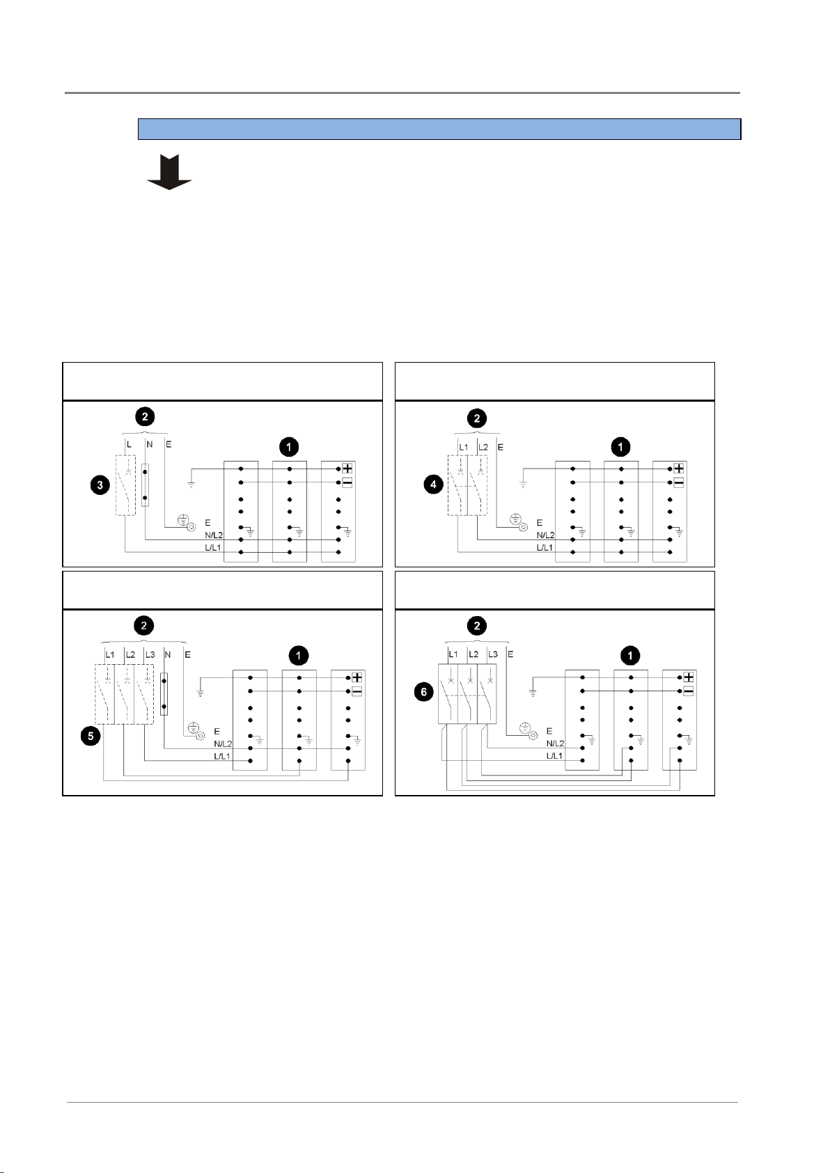
Check the ac terminals on the APS are connected to suit the type of ac supply. Refer
to the ac connection diagrams in Step 6.
Access Power Solutions dc power systems can only be connected to one of the
following:
AC source
Voltage (nominal)*
AC MCB
(if fitted)
1-phase, neutral and Protective Earth (PE)
220-240V phase-neutral
1-pole
2-phase and PE
208V phase-phase
2-pole (linked)
3-phase, neutral and PE
220-240V phase-neutral
3-pole
3-phase and PE
208V phase-phase
3-pole (linked)
*See Specifications on page 69 for the ac voltage range.
1 Select ac supply cable to suit the ac supply
source, the maximum ac current (see
Specifications on page 69) and in accordance
with the local wiring regulations.
2 Route the ac supply cable from the ac supply
point into the rack. Then bring the cable through
the front of the rack to the APS.
Do not terminate at the ac supply point at this
stage.
3 At the APS end, cut the conductors to suit the
positions of the terminals (and ac MCB(s) if
fitted).
Ensure the earth conductor is 30-50mm (1¼ - 2
inches) longer than the longest phase or neutral
conductor.
Rack cabinet
Proposed position of APS
AC cable from supply point
(top or bottom entry into
rack as required).
1 Position the APS in front of the rack.
2 Terminate the earth conductor with an M6 crimp lug.
Ensure the ferrule of the crimp lug covers all strands of wire.
3 Connect the earth conductor to the earth termination point next to the ac
terminals (see the diagram on page 3).
Step 3 - Check the connection of the ac terminals
Step 4 - Prepare the ac supply cable
Step 5 - Terminate the earth conductor at APS
Access Power Solutions Installation and Operation Guide (APS3-300 Series)
24
Copyright © 2007-2012 Eaton Corporation. All Rights Reserved.
IPN 997-00012-48D November 2012
1 If ac MCB(s) fitted then connect the phase conductor(s) to the MCB(s).
Ensure the insulating card covers the MCB terminal(s).
2 If no ac MCB(s) fitted then terminate the phase conductor(s) with M4 crimp
lug(s) and connect to the ac terminal(s) according to the following diagram that
corresponds to the ac supply source.
Ensure the ferrules of the crimp lugs cover all strands of wire.
3 If fitted, terminate the neutral conductor with an M4 crimp lug and connect to
the ac terminal according to the following diagram that corresponds to the ac
supply source.
Ensure the ferrules of the crimp lug covers all strands of wire.
1-phase, neutral and Protective Earth (PE)
2-phase and PE
3-phase, neutral and PE
3-phase and PE
Rectifier modules
AC supply
Optional 1-pole ac MCB
Optional 2-pole (linked) ac MCB
Optional 3-pole ac MCB
3-pole (linked) ac MCB
Positive earth system shown.
Step 6 - Terminate the phase and neutral (if used) conductor(s) at APS
 Loading...