

Eaton AMT Vari-Depth Instruction Leaflet
Instruction Leaflet IL14946I
Effective November 2012
Supersedes IL14946H 03/98
Instructions for Type AMT Vari-Depth® Handle
Mechanism for Above Handle (Variable-Width)
Contents
Description Page
Assembly Instructions . . . . . . . . . . . . . . . . . . . . . . 3

Instruction Leaflet IL14946IB
mounting but may be converted to left hand mounting by moving the drive bushing on the yoke assembly to the left side. Transpose dimensions and
Note: This mechanism is assembled for right hand
instructions as required.
DO NOT ATTEMPT TO INSTALL OR PERFORM
MAINTENANCE ON EQUIPMENT WHILE IT IS ENERGIZED. DEATH, SEVERE PERSONAL INJURY, OR
SUBSTANTIAL PROPERTY DAMAGE CAN RESULT
FROM CONTACT WITH ENERGIZED EQUIPMENT.
ALWAYS VERIFY THAT NO VOLTAGE IS PRESENT
BEFORE PROCEEDING WITH THE TASK, AND
ALWAYS FOLLOW GENERALLY ACCEPTED SAFETY PROCEDURES.
EATON IS NOT LIABLE FOR THE MISAPPLICATION
OR MISINSTALLATION OF ITS PRODUCTS,
The user is cautioned to observe all recommendations,
warnings, and cautions relating to the safety of personnel and equipment as well as all general and local
health and safety laws, codes, and procedures.
The recommendations and information contained herein
are based on Eaton experience and judgment, but
should not be considered to be all-inclusive or covering every application or circumstance which may
arise. If any questions arise, contact Eaton for
further information or instructions.
!
WARNING
Effective November 2012
Instructions for Type AMT Vari-Depth® Handle
Mechanism for Above Handle (Variable-Width)
2
EATON CORPORATION www.eaton.com
Instructions for Type AMT Vari-Depth® Handle
ASSEMBLY INSTRUCTIONS
1. Locate mechanism and circuit breaker or disconnect
switch as per outline and drilling plans on following
pages.
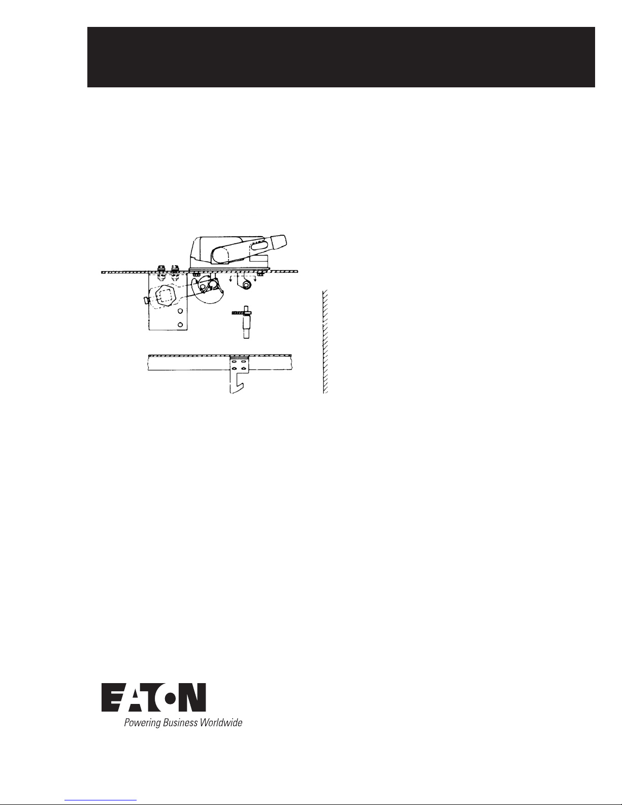
2. Assemble external handle and pivot assembly to the
enclosure.
3. Place spring on the long pin with legs facing away
from the pin head. Connect the handleassembly and
pivot assembly with the long pin.
4. With the handle in the extreme OFF (open cover)
position put the spring legs in place as shown in
Fig. 1.
5. Mount the circuit breaker or discon
nect switch with
the backplate and yoke assembly.
6. Determine brace length as shown on page 5 and
mount in place.
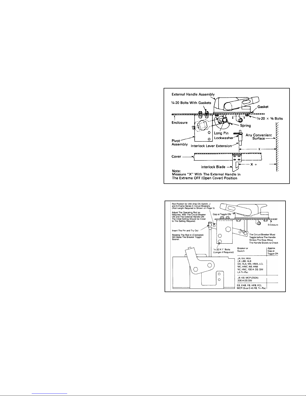
7. Connect operating rod as per instructions in Fig. 2.
8.
Mount interlock blade and interlock lever extension.
Check the position of the interlock blade as shown
in Fig. 1. before closing the
cover.
The external handle should remain against the stop, or
nearly against the stop, when the circuit breaker is ON.
The external handle must move the circuitbreaker handle
to the extreme OFF (Reset) position before reaching its
stop.
It must be possible to move the external handle to the
extreme OFF (open cover) position. In this position the
operating mechanism is being forced beyond the final
breaker handle position and distortion will be evident on
the ope
rating mechanismpartsinside the enclosure.This
will be especially evident on the 800 and 1200 Amp circuit breakers.
Fig. 1.
Fig. 2.
1/32(0.79)
9.
1/4 -1/2
(6.35- 12.70)
3/8 -5/8
(9.53- 15.88)
9/16 - 15/16
(14.29 - 23.81)
Mechanism for Above Handle (Variable-Width)
Instruction Leaflet IL14946I
Effective November 2012
EATON CORPORATION www.eaton.com
3
 Loading...