

Eaton AMPGARD Series, AMPGARD MV4S Instructions For Installation, Use And Maintenance Manual
Cutler-Hammer
Instructions for Installation, Operation, and Maintenance
of the AMPGARD Reduced Voltage Soft Starter
Instruction Bulletin
Read and understand these instructions
before attempting any installation,
operation, or maintenance of the
AMPGARD Reduced Voltage Soft Starter.
This equipment shall be installed and
serviced only by qualified electrical
personnel.
Retain this document for future use.
For more information vi sit: www.cutler-hamm er.eaton.com
IB48068

Instruction Leaflet Instructions for Installation,
Page 2 Effective: March 2010 Operation, and Maintenance of the
AMPGARD Reduced Voltage Soft Starter
Cutler-Hammer
Table of Contents
Description Page
Purpose………………………………………………………………..2
1 Introduction..…………………………………………………. 3
1.1. Basic Description of a Single Unit………………. 3
1.2. Upper Cell………………………………………………. 3
1.3. Lower Cell………………………………………………. 4
1.4. RVSS Truck……………….……………………………. 5
2 Installation…………………………………………………….. 5
2.1 RVSS Truck Removal………..……………………… 6
2.2 RVSS Truck Transport……………………………… 9
2.3 Cable Shield Removal……………………………... 9
2.4 RVSS Truck Reinstallation………………………. 10
3 Operation…………………………………………………..... 11
3.1 Reduced Voltage Operation…………………… .11
3.2 Full Voltage Operation…………………………….13
For more information vi sit: www.cutler-hamm er.eaton.com
HAZARDOUS VOLTAGE
ALL POWER SOURCES MUST BE
ISOLATED AND LOCKED OUT
BEFORE SERVICING THE
EQUIPMENT.
READ AND UNDERSTAND THESE
INSTRUCTIONS IN THEIR ENTIRETY
BEFORE INSTALLING, OPERATING,
OR MAINTAINING THIS
EQUIPMENT. ONLY QUALIFIED
PERSONS SHOULD INSTALL,
MAINTAIN, ADJUST, OR REPAIR
THESE UNITS. A QUALIFIED
PERSON IS ONE WHO IS FAMILIAR
WITH THE CONSTRUCTION AND
OPERATION OF THE EQUIPMENT
AND THE HAZARDS ASSOCIATED
WITH IT.
Purpose
This instruction book is to ensure the safe and
successful installation, operation, and
maintenance of the AMPGARD Reduced Voltage
Soft Starter (RVSS). This equipment may be
installed as an individual structure or may be part
of a lineup of AMPGARD products.
IB48068
Instruction Leaflet Instructions for Installation,
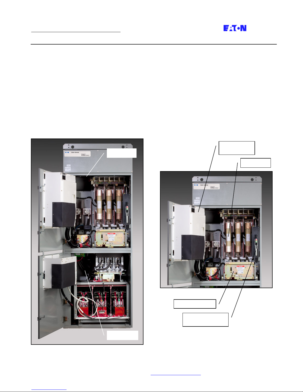
Upper Cell
Lower Cell
Compartment
Main Contactor
Main Fuses
Page 3 Effective: March 2010 Operation, and Maintenance of the
AMPGARD Reduced Voltage Soft Starter
Section 1 – Introduction
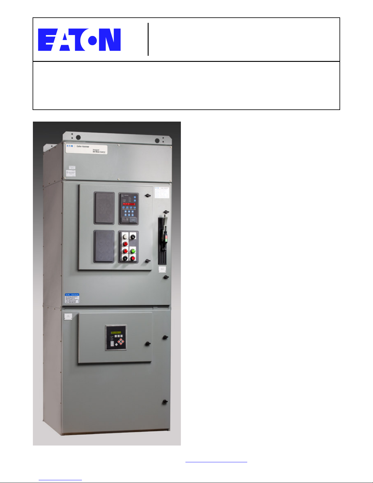
1.1 Basic Description of a Single Unit
The AMPGARD RVSS is designed to start medium
voltage motors at reduced voltages with specific
ramp times and amperages. An individual unit
consists of a standard structure that is 36 inches
wide by 30 inches deep by 92 inches tall, including
the main bus. The top half is referred to as the
upper cell and the bottom half as the lower cell.
(See Fig. 1.)
1.2 Upper Cell
The upper cell consists of a full voltage starter with a
non-load break isolation switch, medium voltage
current limiting fuses, an SL contactor, and current
transformers. A low voltage control compartment is
located on the front of the controller medium voltage
door. (See Fig. 2.) Refer to IB48041 (Instructions
for AMPGARD 400 Ampere Medium Voltage Starter)
for operating and maintenance instructions on the
upper cell.
Cutler-Hammer
Low Voltage
Fig. 1 AMPGARD RVSS
Fig. 2 Upper Cell
Isolation Switch
Handle Mechanism
For more information vi sit: www.cutler-hamm er.eaton.com
IB48068
Instruction Leaflet Instructions for Installation,
Door Interlock Tab
Compartment
Assembly
Page 4 Effective: March 2010 Operation, and Maintenance of the
AMPGARD Reduced Voltage Soft Starter
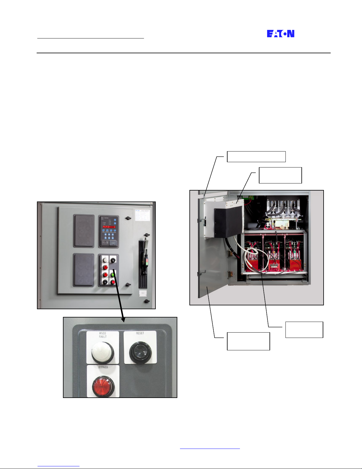
The following components are located on the front of
the low voltage door of the upper cell. (See Fig. 3.)
• Bypass Mode Indicating Light – After the motor
is started and reaches speed, the bypass
contactor closes to bypass the SCRs in the soft
starter. The Bypass Mode Indicating Light will
illuminate when the SCRs are bypassed.
• RVSS Fault Indicating Light – In the event of a
soft starter failure, the RVSS Fault Indicating
Light will illuminate.
• RVSS Fault Reset Pushbutton – In the event of
a soft starter failure, the RVSS Fault Reset
pushbutton must be depressed to clear the
fault.
• Optional start-stop pushbuttons and run-
stopped indicating lights are supplied when
specified.
1.3 Lower Cell
The lower cell consists of a welded frame with rails
for the AMPGARD RVSS truck assembly. There is a
medium voltage door with a flange that prevents
access to the lower cell until the isolation switch and
upper door have been opened to ensure that line
voltage is not present. The RVSS truck assembly is
shown racked into place in Fig. 4.
Cutler-Hammer
Low Voltage
Fig. 4 Lower Cell
Medium
Voltage Door
Fig. 3 Low Voltage Components
RVSS Truck
For more information vi sit: www.cutler-hamm er.eaton.com
IB48068
 Loading...