

Eaton Ampgard 720A Instructions For Installation, Operation And Maintenance
Instruction Booklet IB48066
Effective November 2010
Instructions for Installation, Operation and Maintenance
of the Ampgard 720A Reduced Voltage Soft Starter
Contents
Description Page
Purpose ................................. 2
Introduction .............................. 2
1.1 Basic Description of a Single Unit ........ 2
1.2 Main Cell ........................... 3
1.3 Bypass Cell .......................... 4
1.4 RVSS Cell ........................... 4
Operation ................................ 5
Instruction Booklet IB48066
Effective November 2010
Instructions for Installation, Operation and Maintenance
of the Ampgard 720A Reduced Voltage Soft Starter
Read and understand these instructions before attempting any
installation, operation or maintenance of the Ampgard Reduced
Voltage Soft Starter.
This equipment shall be installed and serviced only by qualified
electrical personnel.
Retain this document for future use.
DANGER
HAZARDOUS VOLTAGE
ALL POWER SOURCES MUST BE ISOLATED AND LOCKED OUT BEFORE
SERVICING THE EQUIPMENT.
READ AND UNDERSTAND THESE INSTRUCTIONS IN THEIR ENTIRETY
BEFORE INSTALLING, OPERATING, OR MAINTAINING THIS EQUIPMENT.
ONLY QUALIFIED PERSONS SHOULD INSTALL, MAINTAIN, ADJUST OR
REPAIR THESE UNITS. A QUALIFIED PERSON IS ONE WHO IS FAMILIAR
WITH THE CONSTRUCTION AND OPERATION OF THE EQUIPMENT AND THE
HAZARDS ASSOCIATED WITH IT.
Purpose
This instruction book is to insure the safe and successful installation,
operation and maintenance of the Ampgard 720A Reduced Voltage
Soft Starter (RVSS). This equipment may be installed as an individual
structure or may be part of a lineup of Ampgard products.
Section 1: Introduction
1.1 Basic Description of a Single Unit
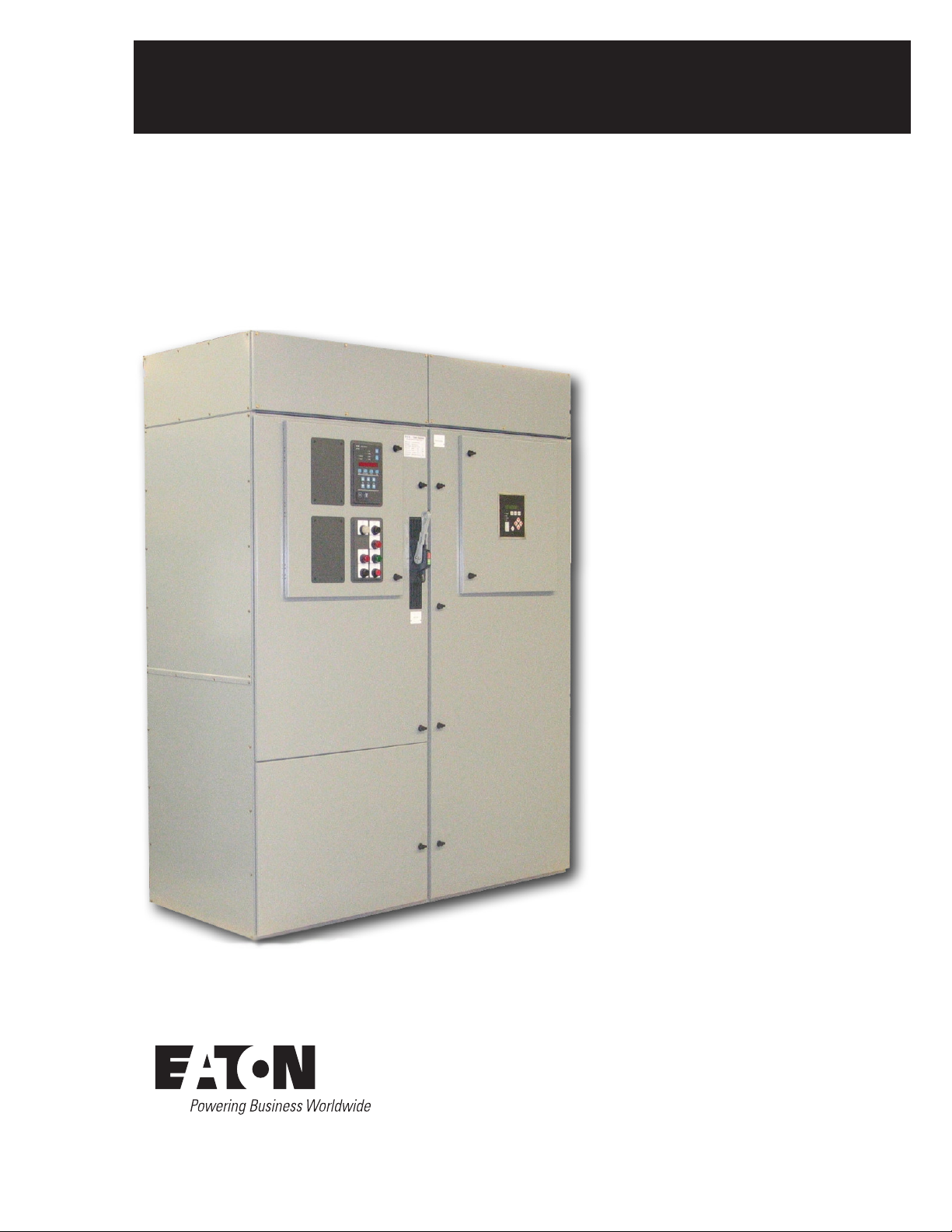
The Ampgard RVSS is designed to start medium voltage motors
at reduced voltages with specific ramp times and amperages. An
individual unit is 72 in wide x 30 in deep and 92 in tall, including the
main bus. An additional structure for incoming line cables may also
be supplied. The left structure is referred to as the main structure
and the right structure is the RVSS cell. The upper portion of the
main structure is referred to as the main cell and the lower portion is
the bypass cell. (See Fig. 1.)
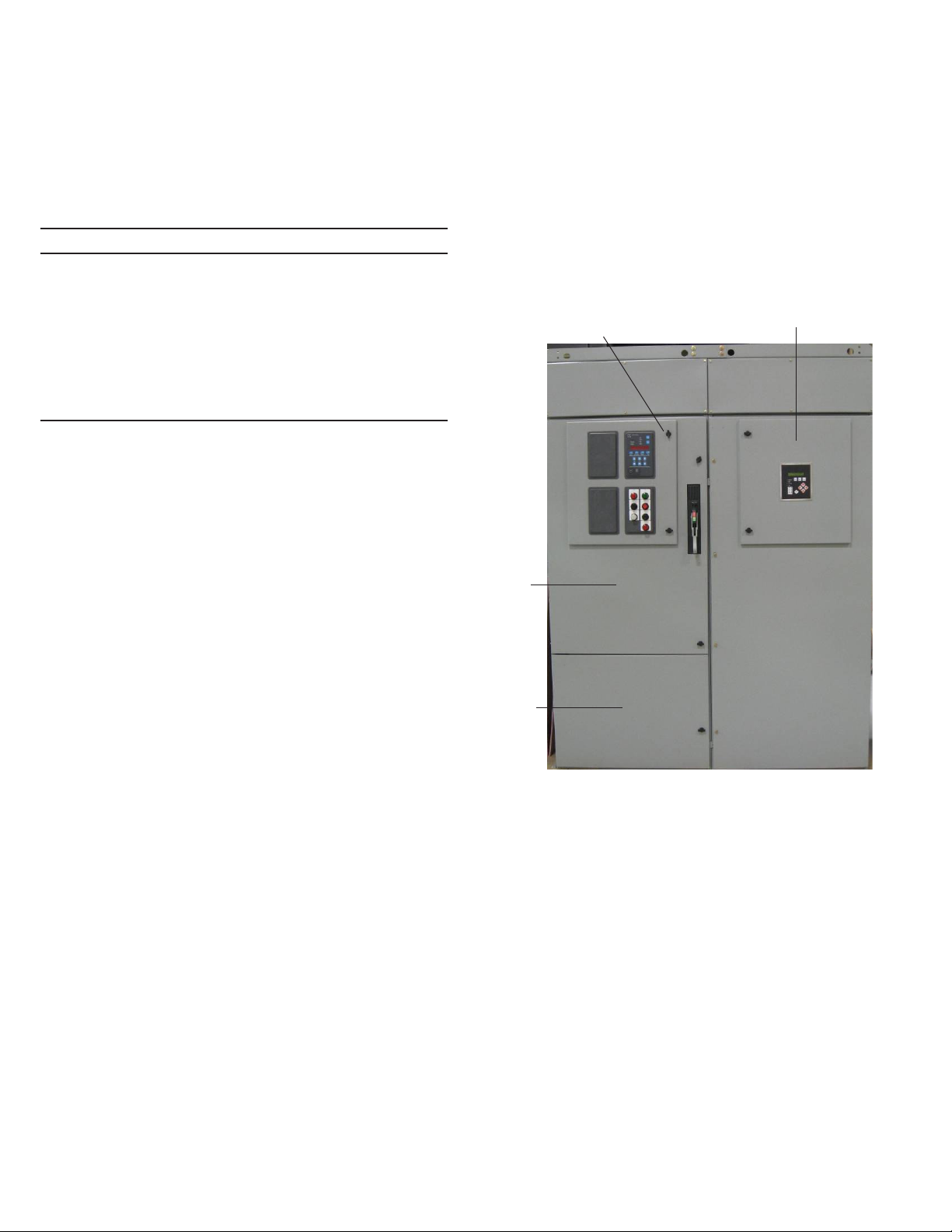
Main
Structure
RVSS Cell
Main
Cell
Bypass
Cell
Figure 1. Ampgard 720A RVSS Unit
2
EATON CORPORATION www.eaton.com
Instructions for Installation, Operation and Maintenance
of the Ampgard 720A Reduced Voltage Soft Starter
Instruction Booklet IB48066
Effective November 2010
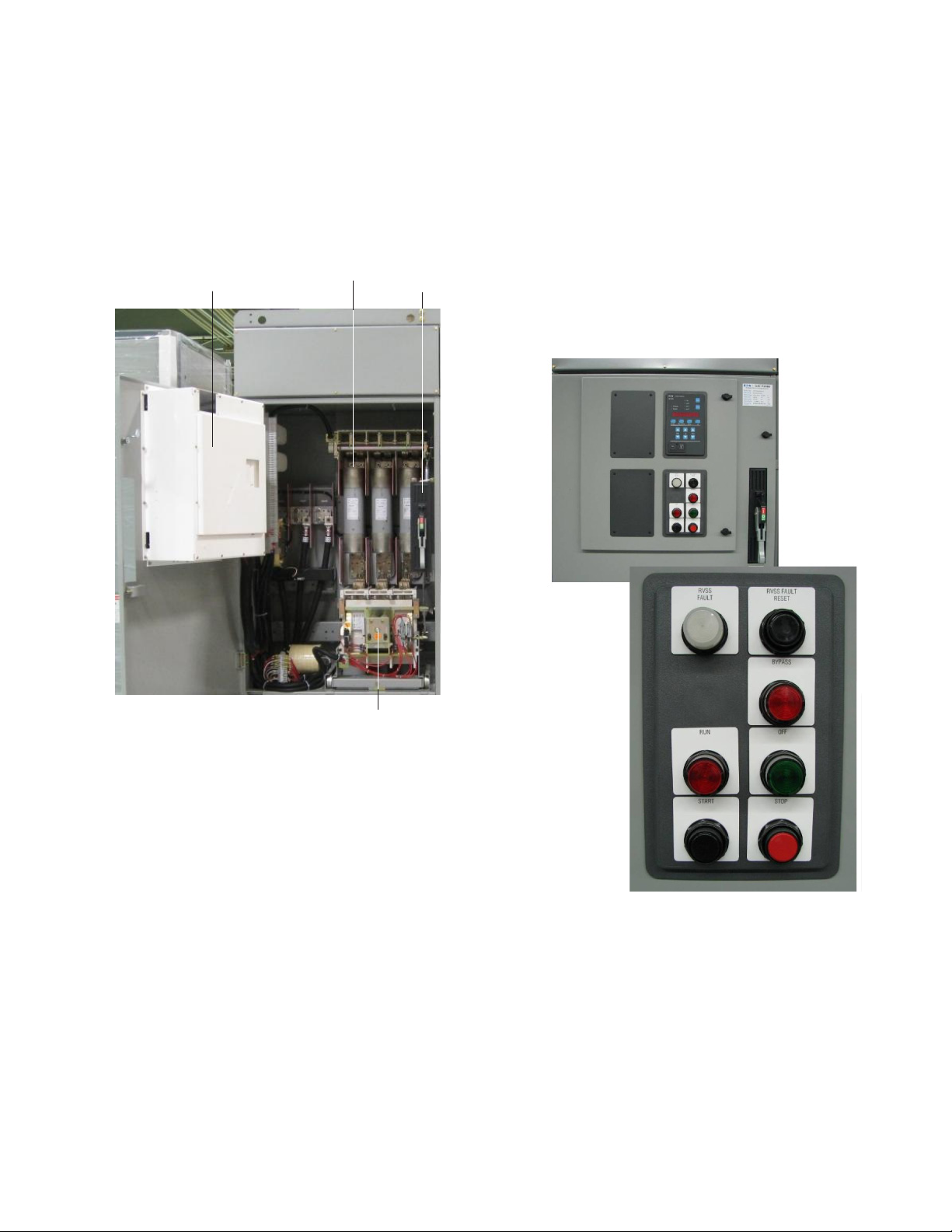
1.2 Main Cell
The upper cell consists of a full voltage starter with a non-load
break isolation switch, medium voltage current limiting fuses, an SL
contractor, and current transformers. The low voltage control compartment is located on the front of the medium voltage door. (See
Fig. 2.) Refer to IB48043 (Instructions for Ampgard 720A Ampere
Medium Voltage Starter) for operating and maintenance instructions
on the main cell.
Low Voltage
Compartment
Main Fuses
Isolation
Switch
The following components are located on the front of the low voltage door of the main cell. (See Fig. 3)
• Bypass Mode LED – After the motor is started and reaches
speed, the bypass contactor closes to bypass the SCRs in the
soft starter. The Bypass Mode Indicating Light will illuminate
when the SCRs are bypassed.
• RVSS Fault LED – In the event of a soft starter failure, the RVSS
Fault LED will illuminate.
• RVSS Fault Reset Pushbutton – In the event of a soft starter fail-
ure, the RVSS Fault Reset pushbutton must be depressed to clear
the fault.
• Optional start-stop pushbuttons and runstopped indicating lights
are supplied when specified.
Figure 2. Main Cell
Main
Contactor
Figure 3. Low Voltage Components
EATON CORPORATION www.eaton.com
3
 Loading...