

Eaton AMPGARD Installation, Operation And Maintenance Instructions
Instruction Booklet IB48050
Effective September 2012
Instructions for installation,
operation, and maintenance of the
AMPGARD 15 kV, 300A vacuum starter
Contents
Description Page
Introduction ..............................2
Identification .............................2
Description ..............................2
Controller ..............................2
Ratings ................................3
Low voltage components. . . . . . . . . . . . . . . . . . 4
Isolation switch .........................4
Power fuses ............................5
Vacuum contactor .......................6
Safety interlocks .........................6
Low voltage control ......................7
Current transformers .....................7
Main bus ..............................8
Installation. ..............................8
Handling ...............................8
Storage ................................8
Mounting ..............................8
Bus splicing ............................8
Power connections .......................8
Motor load cable termination ...............9
Control connections ......................9
Setting of adjustable protective devices .....10
Pre-startup checks. .......................10
Maintenance. ............................12
Insulation level .........................12
Fuses ................................12
Contactor .............................12
Isolation switch ........................13
Door interlock ..........................15
Instruction Booklet IB48050
Effective September 2012
Instructions for installation,
operation, and maintenance of the
AMPGARD 15 kV, 300A vacuum starter
m Danger
reaD anD unDerstanD this manual in its entirety before
installing or operating controller. installation, aDjustment,
repair anD maintenance of these controllers must be
performeD by qualifieD personnel. a qualifieD person is
one who is familiar with the construction anD operation
of this equipment anD the hazarDs involveD.
Introduction
This instruction book is intended to cover the handling, installation,
operation, and maintenance of AMPGARDT 300A, 15 kV starters
and associated equipment. The function of these controllers is
to start, stop, and protect medium voltage motors, transformers,
and other loads. Controllers may be of full voltage, reduced voltage
reactor, reduced voltage autotransformer, or two-speed type.
They may control induction or synchronous machines, and may
be non-reversing or reversing.
While this instruction book is dedicated primarily to full-voltage
starting, the other applications listed are an expansion of the
principles identified in this book. This book does not purport to
cover all possible contingencies, variations, and details that may
arise during operation or maintenance of this equipment.
If further information is desired regarding this product, contact
your local Eaton sales office.
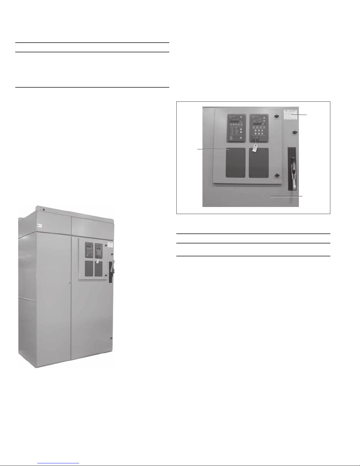
Identication
A rating nameplate is located on the door of each controller.
Contained on this nameplate are the controller type and ratings as
required by industry standards. Also contained on this nameplate
is the factory’s general order number. This number should be given
to the Eaton sales office if a question should arise concerning the
equipment or if renewal parts are required. Refer to Figure 2 for
typical location of rating nameplates.
Rating
Nameplate
Low
Voltage
Door
Medium
Voltage
Door
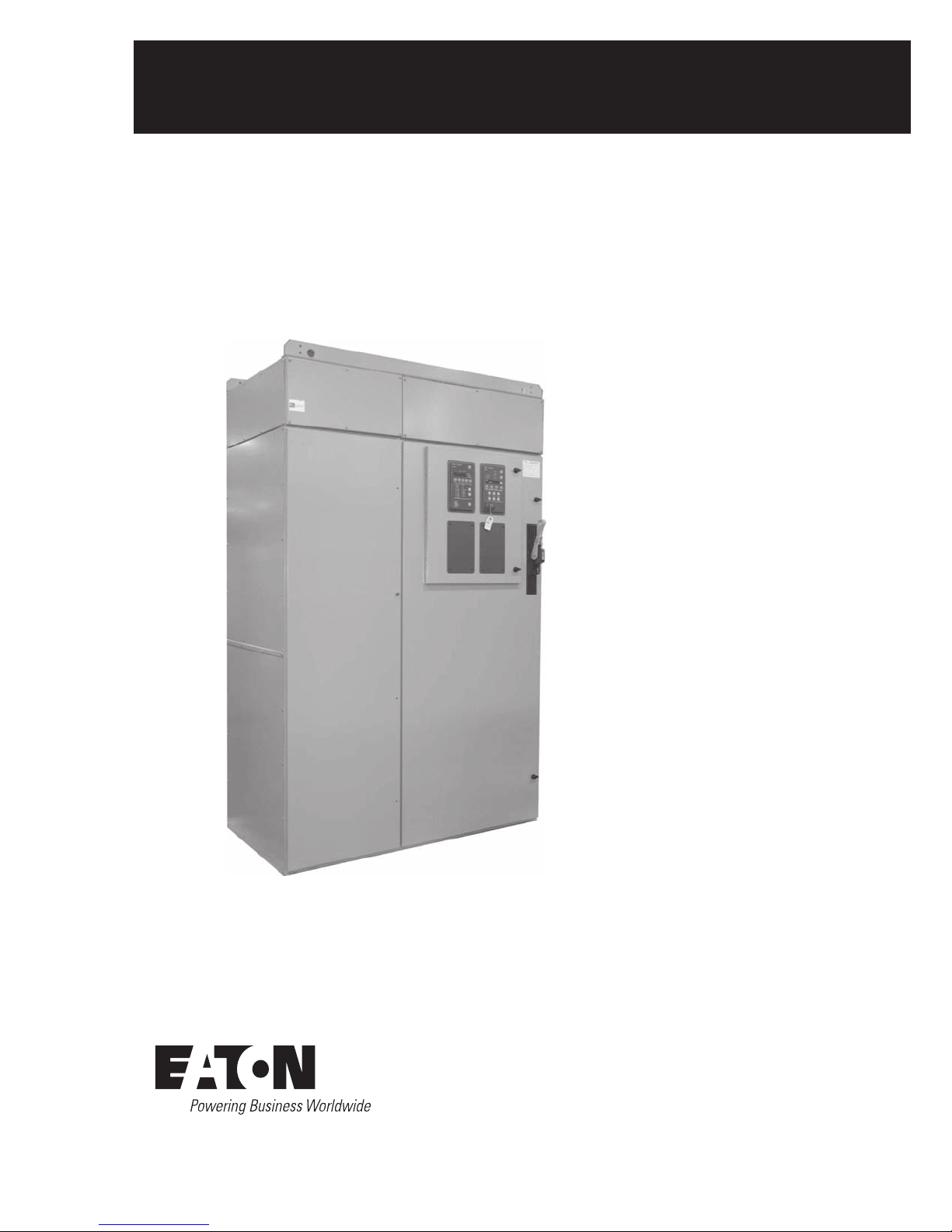
Figure 1. 15 kV Starter with Incoming Cable Section
Figure 2. Starter with Rating Nameplate
m Danger
exceeDing the nameplate ratings of an ampgarD controller
may cause equipment Damage, severe injury, or Death.
Do not apply an AMPGARD controller beyond its nameplate ratings.
Description
Controller
The AMPGARD 300A, 15 kV controller consists of a non-loadbreak
isolation switch, medium voltage current limiting fuses, one or
more Type SL 15 kV vacuum-break contactors, a set of current
transformers, plus control and protection devices. The isolating
switch has a limited make and break rating, suitable only for closing
and opening limited transformer magnetizing currents. The controller
is designed to start, stop, and protect a three-phase medium voltage
motor within the ratings shown in Table 1 and Table 2. The controller
may also be used to switch transformer windings as shown. For
applications other than those indicated, consult the factory. Each
AMPGARD controller occupies all or a portion of a steel structure
that may also enclose a horizontal bus system to distribute power
to two or more sections and a vertical bus system to connect
individual starters to the horizontal bus. The controllers are
configured for full-voltage or reduced voltage starting, reversing
or non-reversing, in single-speed or two-speed applications.
2
EATON CORPORATION www.eaton.com

Instructions for installation,
operation, and maintenance of the
Instruction Booklet IB48050
Effective September 2012
AMPGARD 15 kV, 300A vacuum starter
Ratings
Table 1. Starter Ratings
Utilization Voltage Rating
Description
Interrupting rating E1 (unfused) 5 kA 5 kA
E2 (fused) 950 MVA at 11,000V 1190 MVA at 13,800V
E2 (fused) 63 kA 63 kA
Continuous current 300A 300A
Induction motor 6000 hp 7500 hp
Synchronous motor (0.8 PF) 6000 hp 7500 hp
Synchronous motor (1.0 PF) 6750 hp 8500 hp
Transformer 5400 kVA at 11 kV 6800 kVA at 13.8 kV
BIL 75 kV 95 kV (with arrestors)
Table 2. SL Contactor Ratings
Description Rating
Maximum voltage 15,000V
Maximum interrupting current
(three operations)
Rated current 300A enclosed/300A open
IEC make-break capability
AC3—Make
AC3—Break
Short time current
30 seconds
1 second
8.75 milliseconds
Mechanical life 1 million operations
Electrical life 100,000 operations
Dielectric strength (60 Hz) 36 kV (1 minute)
Closing time 80 milliseconds
Opening time 130 to 330 milliseconds (selectable)
Weight 95 lbs (43 kg)
Arcing time 12 milliseconds (3/4 cycle) or less
Pickup voltage 80% rated coil voltage
5000A
3200A
2560A
1920A
4800A
25 kA peak
10,000 to 11,000V 12,400 to 13,800V
Description Rating
Dropout voltage 60% rated coil voltage
Control voltages
AC
DC
Control circuit burden (rated volt)
Closing
Holding
Auxiliary contact ratings
Voltage (maximum)
Continuous current
Making capacity (AC)
Making capacity (DC)
Breaking capacity (AC)
Breaking capacity (DC)
Latch (when specified)
Mechanical life
Trip voltages (DC)
Trip voltages (AC)
Tripping voltage
Tripping burden
24 Vdc
48 and 96 Vdc
110 and 220 Vac
110/120/220/240V (50/60 Hz)
125V
2600 VA
80 VA
600V
10A
7200 VA
200 VA
720 VA
200 VA
250,000 operations
24/48/96V
110/220V (50/60 Hz)
80% rated coil voltage
1200 VA
400 VA
500 VA
Ratings are based on full voltage starting of standard motors
with locked rotor current equal to 6-times full load current and
an acceleration time of 10 seconds. The starter may be supplied
with a definite purpose rating of up to 300A depending on the
type of starting (reduced voltage autotransformer for example),
locked rotor current, and acceleration time. Consult the factory
for more information.
Starters are supplied with bolt-in main fuses. Contactors have
stab-in connections to the starter cell.
The flow of current through a starter with bolted fuses and a
stab-in contactor can be described as follows: The line finger
assembly mounted at the back of the enclosure serves to connect
the isolation switch moving stabs to the controller line terminals
when the switch is closed. Power flows from the switch moving
stabs through two flexible shunts to the upper fuse mountings.
The fuses are connected to the lower fuse mountings that contain
the line-side stab connections to the line finger assemblies for the
main contactor. With the main contactor energized, power flows
through the contactor’s vacuum interrupters to the contactor load
fingers, which are engaged on to the controller load-side stabs.
Medium voltage cables connect the load-side stabs to the motor
load connections. The contactor is held in place by a set of rails
mounted in the lower part of the cell. For full-voltage starters, the
motor load connections are mounted to the left of the main fuses
in the rear of the compartment, facing forward. For reduced voltage
starters, the motor load connections are mounted in the left rear
of the reduced voltage structure. Current transformers are typically
mounted just below the motor load connections.
EATON CORPORATION www.eaton.com
3
Instruction Booklet IB48050
Effective September 2012
Instructions for installation,
operation, and maintenance of the
AMPGARD 15 kV, 300A vacuum starter
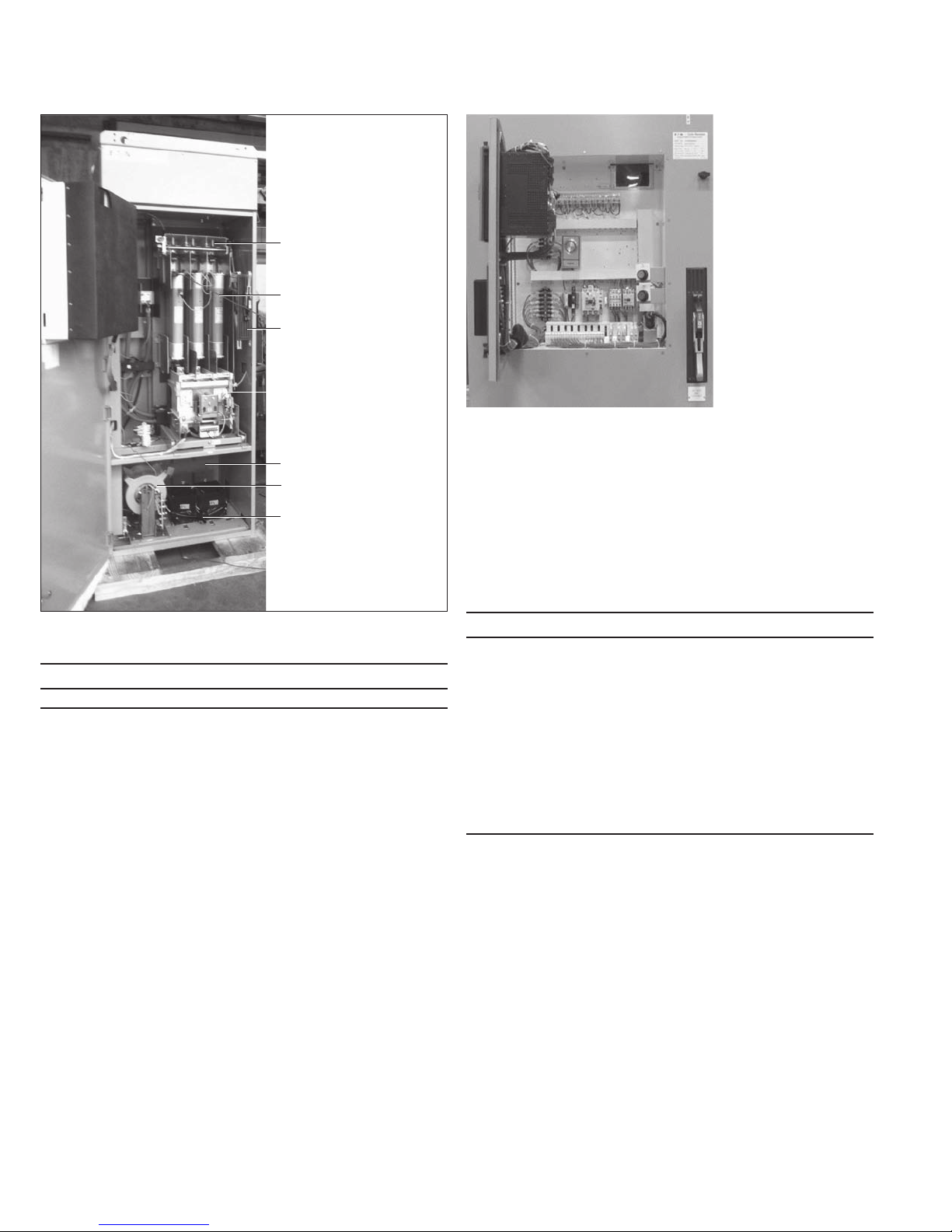
Isolation Switch
Main Fuses
Isolation Switch
Operating Handle
Main Contactor
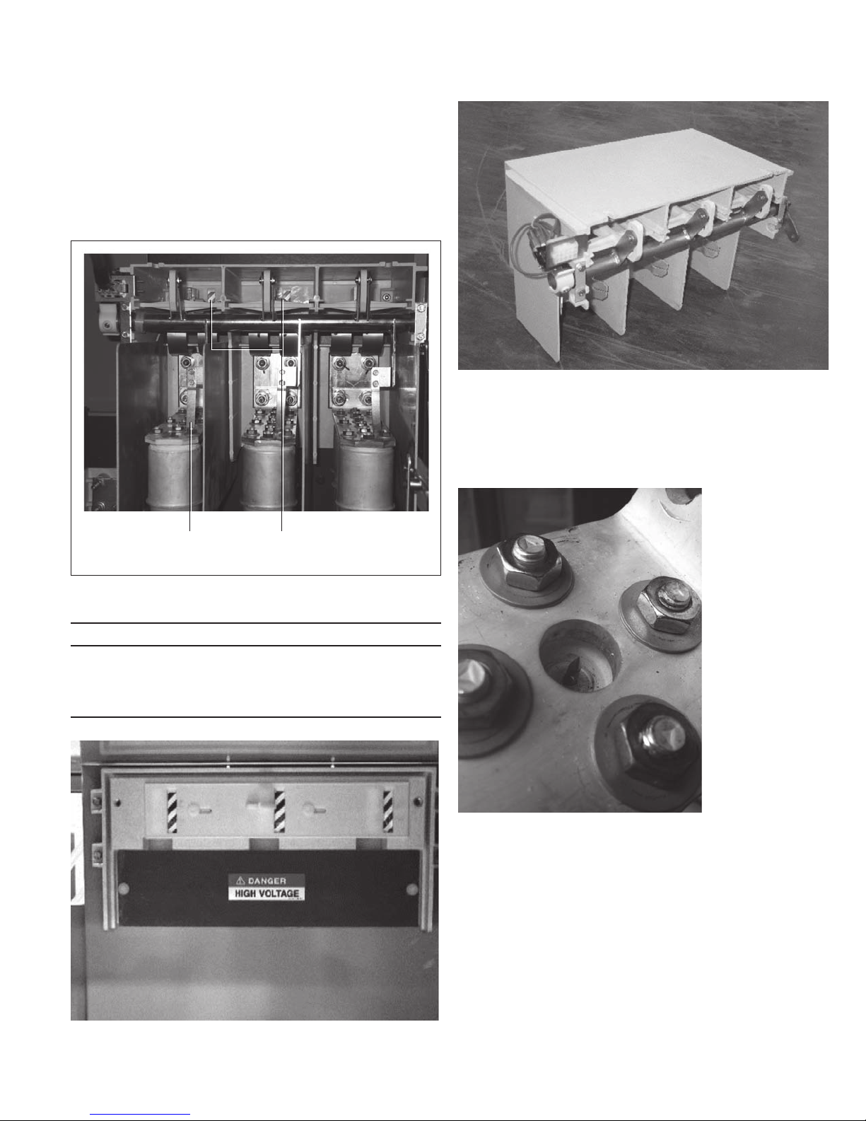
Figure 4. Low Voltage Compartment
CPT/PT Primary Fuses
CPT
PTs
Figure 3. Medium Voltage Compartment
m caution
main fuses weigh 44 pounDs for the 400a-15bhcls-400.
Low voltage components
The low voltage components consisting of a protective relay,
interposing relay, test power circuit, terminal blocks, and optional
equipment are mounted in the low voltage control compartment
located on the front of the controller medium voltage door. The low
voltage compartment is fabricated from steel sheets to provide
isolation from the medium voltage components mounted behind the
low voltage compartment. A window is provided in the low voltage
compartment to allow the user to view the position of the isolation
switch before entering the medium voltage compartment. See
section on Isolation Switch for further details.
Isolation switch
The controller isolation switch is a non-loadbreak device.
Mechanical and electrical interlocks are provided to ensure that the
main contactor is de-energized before the switch can be operated.
In the open position, the switch isolates medium voltage from the
main controller compartment, allowing access to the controller for
inspection and maintenance. For standard applications, the isolation
switch includes ground fingers that ground the line side of the
power fuses when the switch is in the open position.
m Danger
ampgarD controllers are sometimes energizeD by a back-feD
conDition that allows the meDium voltage compartment to
be energizeD with the isolation switch in the open position.
stuDy the plant single-line Diagrams to make certain that
no back-feeD situation exists before entering the meDium
voltage compartment.
all power sources must be isolateD anD lockeD out before
servicing the equipment.
for applications where the controller is back feD,
the grounDing fingers shoulD be removeD from the
isolation switch.
The switch consists of a fixed rear portion and a removable front
portion. Refer to Figure 6 and Figure 7. The fixed portion includes
the controller line fingers and a moveable shutter that isolates the
line fingers when the switch is in the open position. The removable
portion is operated by a handle mechanism that extends through the
controller medium voltage door. With the handle in the up position,
the switch is closed, and medium voltage is available for connection
to the controller load. With the handle in the down position, the
switch is open, and medium voltage is isolated from the controller
and the controller load.
4
EATON CORPORATION www.eaton.com
Instructions for installation,
operation, and maintenance of the
AMPGARD 15 kV, 300A vacuum starter
An isolation switch viewing window is provided in the upper rear
corner of the low voltage control compartment. After opening the
isolation switch and before opening the medium voltage door, the
switch should be visually examined through the viewing window to
verify that it is in the open position. Three green and white “barber
poles” will be visible when the switch is in the open position and
the shutter assembly is in the isolating position. See Figure 5 for
location of barber poles. The use of a flashlight will help in verifying
the position of the “barber poles”.
Instruction Booklet IB48050
Effective September 2012
Figure 7. Removable Portion—Isolation Switch
Power fuses
AMPGARD controllers are supplied with Eaton Type BHCLS current
limiting power fuses. Fuses are of the bolt-in type. All fuses include
an indicator that pops up when the fuse has blown.
Grounding
Fingers (3)
Figure 5. Shutter Closed
Barber Poles Indicating
Shutter Closed
m Danger
Do not enter the meDium voltage starter compartment
without visually verifying that the isolation switch is open
anD the isolating shutter is in place. entering a compartment
without the isolating shutter in place may result in severe
injury or Death.
Figure 8. Blown Fuse Indicator
Figure 6. Fixed Portion—Isolation Switch
EATON CORPORATION www.eaton.com
5
 Loading...