

Eaton All-Pro WPS2040M Instruction Manual
WPS2040M
Instruction Manual/Manuel d’instructions/Instrucciones
Questions?/Des questions?/¿Preguntas? 1-800-334-6871 ConsumerProducts@eaton.com
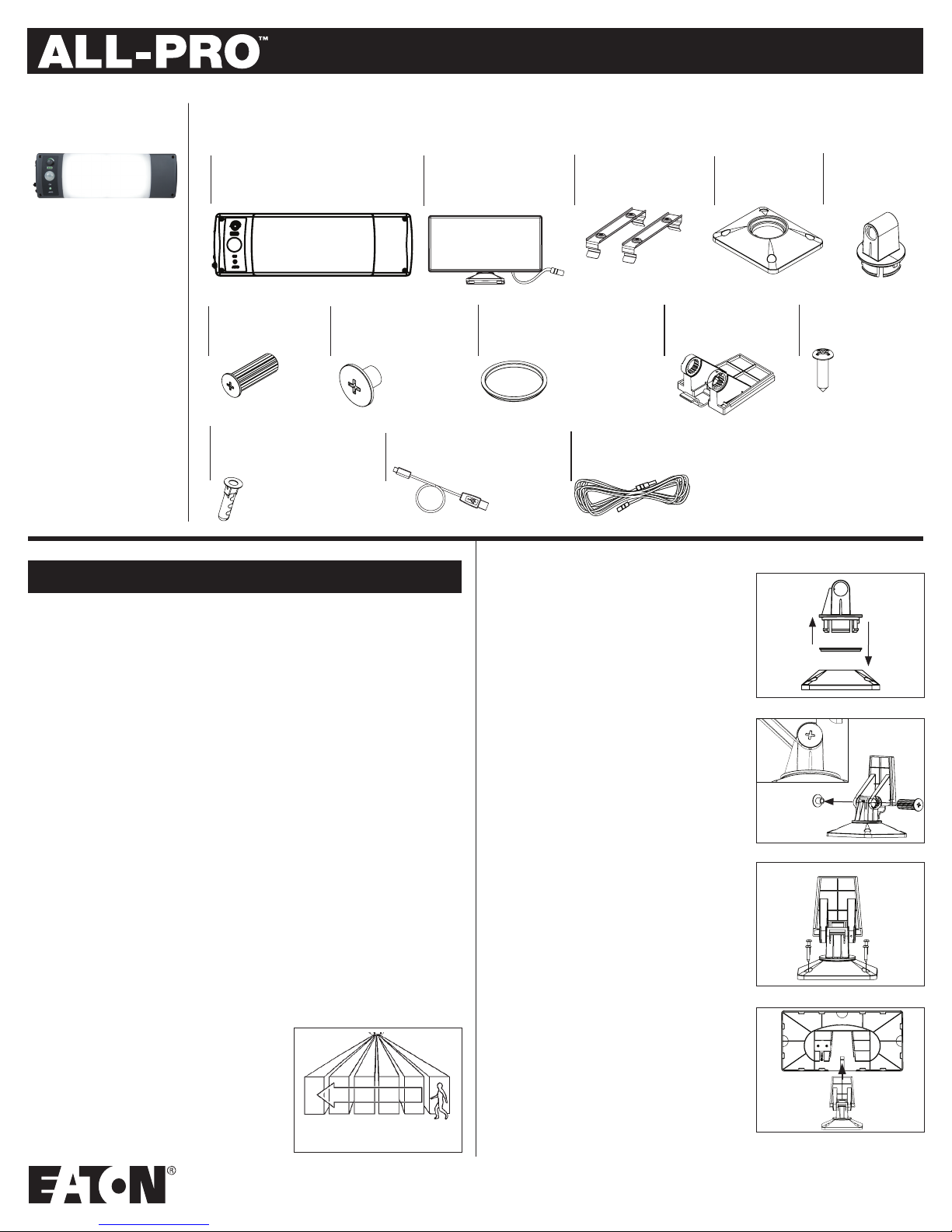
PACKAGING CONTENTS/ CONTENIDO DEL PAQUETE
A. Light fixture
Luminaire
Luminaria
B. Solar panel with 3ft. cord
Panneau solaire avec
cordon de 0,9 m (3 pi)
Panel solar con cable de
3 pies (0,91 m)
C. (2) Mounting brackets
(2) Supports de montage
(2) Soportes de montaje
D. Mounting base
Base de montage
Base de montaje
E. Mounting stand
Socle de montage
Plataforma de
montaje
F. Mounting pin
Goupille de montage
Clavija de montaje
K. (4) Drywall anchors
(4) dispositifs d’ancrage
pour cloison sèche
(4) Anclajes para panel de yeso
G. Mounting pin cap
Capuchon de goupille
de montage
Tapa para clavija de
montaje
L. 6ft.USB Cable
De 1,8 m (6 pi) Câble USB
Cable USB de 6 pies (1,8 m)
ENGLISH
ITEMS REQUIRED
(Purchase separately)
• Phillips screwdriver
• 3/16” drill bit (for anchors)
• Hammer (for anchors)
PRODUCT OVERVIEW
This lighting system is designed for off-grid operation, utilizing an integrated rechargeable liion battery pack and dimmer control for longer periods of use between charging. The battery
pack can be charged either with the included solar panel, which converts sunlight into energy,
or with an external USB power supply (purchased separately). This system features an
integrated 360° motion sensor that turns the light on automatically when motion is detected
at night or in the dark, and can also be used without the motion sensor, allowing the light to
remain on regardless of motion events or ambient light levels.
WARNINGS AND CAUTIONS
INSTRUCTIONS PERTAINING TO A RISK OF FIRE OR INJURY TO PERSONS.
To reduce the risk of fire or injury to persons, read and follow these instructions:
• DO NOT disassemble the lighting system, housing or components
• DO NOT dispose of this product in fire. Batteries inside this product may explode or leak.
• DO NOT puncture, tamper with, or attempt to modify the battery pack.
• DO NOT install or use this system near sources of excessive heat
• Lithium-Ion batteries must be disposed of in accordance with local waste ordinances and
regulations.
• DO NOT operate a luminaire with a missing or damaged lens.
• DO NOT cut, tamper with, or attempt to modify the solar panel wire or USB cable.
• For indoor or outdoor use.
SAVE THESE INSTRUCTIONS.
FOR BEST RESULTS
• Allow fixture to receive three full days of sunlight
before use.
• Locate solar panel in an area that will receive the
maximum amount of sunlight during the daylight
hours. The solar panel mustreceive at least 3-4 hours
of direct sunlight daily.
Fig. 1
H. Mounting friction gasket
Joint de frottement de montage
Arandela de fricción de montaje
M. 17ft. Solar panel extension cord
De 5 m (17 pi) Rallonge électrique pour le panneau d’alimentation
Cable de extensión para paneles solares de 17 pies (5,18 m)
• Once charged, test the system before permanently installing.
• Position the motion sensor so motion moves across the
detection zone (Fig. 1).
• Keep solar panel clear of any objects that will block
the sunlight. It will be necessary to periodically clean
the solar panel with soft wet cloth.
I. Mounting plate
Plaque de montage
Placa de montaje
INSTALLATION
Solar Panel
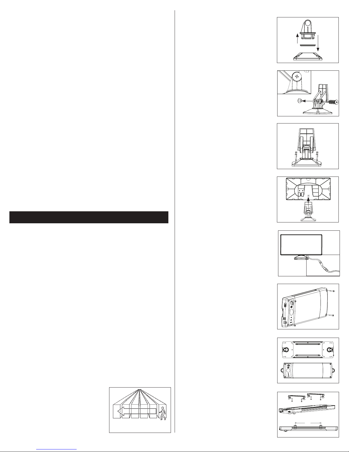
1. Assemble the solar panel mounting bracket (Fig 2):
- Identify the frictional gasket(H) and place on the
mounting stand(E)
- Place the mounting base(D) on a hard flat surface.
Insert mounting stand(E) into the mounting
base(D) until a click is felt and heard.
- Align the arrow on the mounting stand(E) with
the arrow on the mounting plate(I), inserting the
mounting pin(F) through both to lock them together
(Fig 3).
- Push the mounting pin cap(G) into the open end
of the mounting pin(F). The inside edge of the pin
cap(G) should be flush with the mounting plate(I).
2. Choose a location to mount the solar panel(B),
ensuring the solar panel extension cord(M) will reach
the lighting system. For best results the solar panel
should face south, and be clear of any obstructions
that may impede exposure to sunlight. The bracket
provides nearly 360° of rotation, and 120° of tilt.
3. Mount the assembled bracket onto a solid surface,
using four of the mounting screws(J) (Fig 4).
4. Slide the solar panel(B) onto the solar panel
mounting plate(I) until an audible click is felt and
heard (Fig. 5). Make any final adjustments to the
panel to optimize exposure to sunlight.
Lighting System
1. Before installing, check to ensure the included solar
panel extension cord(M) will reach the solar panel
input on the endcap (Fig. 6 ).
2. Mount your lighting system choosing one of three
methods: Direct Mount, D-Ring, or Bracket Mount.
J. (8) Mounting screws
(8) vis de montage
(8) Tornillos de montaje
Fig. 2
E ---
H --D ---
Fig. 3
E
I
D ---
Fig. 4
Fig. 5
B--
CLICK
I
G
F
J
--I
1
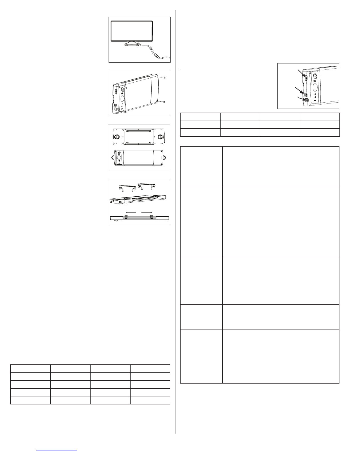
Direct Mount:
Using the 4 of the mounting screws provided(J), attach
the lighting system directly to a wall or ceiling using
the attachment points located in the corners (Fig. 7). If
anchors(K) are required, i.e. for drywall installation, use a
3/16” drill bit to create pilot holes and set the anchors in
place with a hammer.
D-Ring:
Your lighting system can be hung or suspended by one
or both of the D-Rings. Simply rotate one or both rings
out from the housing, ensure the support method used is
securely fastened to the mounting surface, and place the
system into position (Fig. 8).
Bracket Mount:
Attach the two included brackets (C) to a wall or ceiling
using the fasteners provided. Ensure the brackets are
parallel and aligned with each other, positioned no more
than 9" apart (Fig. 9). Locate the grooves on the long
sides of the fixture, rotating and snapping the fixture into
the brackets. Remove by pressing down on the tabs on
the brackets.
Outdoor Installation:
This system is designed to withstand rain and can be
installed and used outdoors, however, the following
guidelines must be adhered to:
• Only the solar panel port can be used when the
system is exposed to moisture. The USB ports are
not designed for use in wet conditions.
• All ports not in use must have the port covers
securely in place at all times to prevent water
intrusion.
• The ports (in a vertical orientation) or control side
(in a horizontal orientation) of the system should
always be oriented downward to protect against
water intrusion.
• The system is designed to operate between 0° and
104°F. To protect the Li-ion battery pack, the internal
charging circuitry will not allow the battery to charge
below 32°F.
Fig. 6
--B
--M
Fig. 7
Fig. 8
Fig. 9
C
9"
FUNCTIONS
Your fixture has three operating modes which can by selected by pressing the power button
repeatedly: ON, AUTO and OFF. As you cycle through these modes the mode text will briefly
illuminate to confirm the mode selected.
ON mode: this mode keeps the light on indefinitely, bypassing inputs from the motion sensor
or photo sensor. Note that in ON mode the system will not shut down until you change modes
or the battery is depleted.
AUTO mode: this mode utilizes the integrated motion sensor and photo sensor, turning the
light on, at night or in the dark, only when motion is detected. The light will deactivate once no
motion has been detected for 3 minutes. The onboard motion sensor has a detection range of
15’ with a detection zone of 360°.
OFF mode: from AUTO mode, press the power button once more to shut the light off. The
charging and discharging functions will continue to operate in OFF mode.
Dimming: the system is equipped with an integrated dimmer that can be used in ON or AUTO
mode. Turn the knob to the left to dim the light output and extend battery run time. Turn the
knob to the right to increase output, which will shorten battery run time. See Table 1 below
for fixture run time estimates.
USB Output: the USB output produces 5V 2.1A, and is useful for charging and/or operating
most smart devices and accessories requiring a USB input. Note that the integrated power
supply is a 8800mAh Li-ion battery pack, and any charging from the power supply will reduce
the run time of the light fixture on a single charge.
TABLE 1
Approximate Run Times and Initial Lumens Based On Dimming Level:
All figures assume the battery pack is fully charged
Dimming Level Full Dimming Half Dimming No Dimming
Light Output 10% 50% 100%
Run Time 18 Hours 9 Hours 90 minutes
Initial Lumen Output 200 1200 2400
Wattage Equivalent 15W 75W 180W
CHARGING
This system is capable of being charged with the included solar panel, or via micro USB.
See Table 2 below for approximate charge times based on power source and input power.
USB Charging:
To charge the fixture using a mini USB charging cord (L), connect the mini USB side of the
cord to the mini USB input on the fixture (Fig. 10). DO NOT use any USB power source
exceeding 5V 2.1A power supply. Once an input charge is detected, the battery indicator will
flash, indicating the battery level. Once the battery is fully charged, the indicator will remain
a solid green.
Solar Panel Charging:
Connect the solar panel cord directly into the solar panel
input port on the fixture (Fig 10); use of the 17’ exten-
sion cord (M) is optional. Please note that the battery
indicatory lights do not come on when charging with the
solar panel in order to conserve power and accelerate
charge time.
TABLE 2.
USB Output
USB Input
Solar panel
input
Fig.10
Typical Charge Times:
Power Source USB USB Solar Panel
Input Power 5V 2.1A 5V 1.0A Full Direct Sun
Charge Time 3.5 Hours 7 Hours 2-3 Days
TROUBLESHOOTING
Light does not come
on when in ON mode
Light does not come
on when in AUTO
mode
Motion Sensor is
malfunctioning
USB output is not
working
Battery Indicator
Lights do not
come on
• Press the power button to cycle through the operating modes,
verifying the level of charge using the battery level indicator.
• Ensure the battery is fully charged, using the USB input if
possible.
• When using the solar panel, allow at least three (3) full sunny
days for the first charge or any time the battery pack becomes
completely depleted.
• The AUTO mode utilizes the integrated photo control and will not
allow the light to come on when ambient light levels are too high.
Ensure ambient light levels are low enough to activate the light.
Test by completely covering the motion sensor with your hand or
other opaque object.
• Press the power button to cycle through the operating modes,
verifying the level of charge using the battery level indicator.
• Ensure the battery is fully charged, using the USB input if
possible.
• When using the solar panel, allow at least three (3) full sunny
days for the first charge or any time the battery pack becomes
depleted.
1. The motion sensor produces a detection zone extending 60°
from center, or 120° total angle. Ensure the motion triggering
event falls within the detection zone.
2. The motion sensor utilizes PIR (passive infrared) technology,
which detects movement and changes in relative heat. Extreme
ambient temperatures may reduce or inhibit motion detection.
3. Relocate the fixture away from trees, moving cars, standing
water or other objects that may potentially cause interference.
• Verify battery level is full using battery level indicator lights by
cycling the power button to the ON mode.
• Verify the USB auxiliary device is compatible with 5V 2.1A input.
• Ensure all connections on USB ports are secure
• Cycle power button to ON mode.
• Battery indicator lights work when in ON mode and may not be
on during AUTO mode when light is off.
• If the main light is off and you are not charging or discharging
using either USB port than the battery indicator light will not be
on. This is intentional to conserve battery life.
• Battery indicator lights do not come on during solar panel
charging and the main light is off. This is intentional to conserve
battery life.
2
1-YEAR LIMITED WARRANTY
THE FOLLOWING WARRANTY IS EXCLUSIVE AND IN LIEU OF ALL OTHER WARRANTIES,
WHETHER EXPRESS, IMPLIED OR STATUTORY INCLUDING, BUT NOT LIMITED TO, ANY
WARRANTY OF MERCHANTABILITY OR FITNESS FOR ANY PARTICULAR PURPOSE.
Eaton warrants to customers that, for a period of one year from the date of purchase,
Eaton products will be free from defects in materials and workmanship. The obligation of Eaton
under this warranty is expressly limited to the provision of replacement products. This warranty
is extended only to the original purchaser of the product. A purchaser’s receipt or other proof
of date of original purchase acceptable to Eaton. This is required before warranty performance
shall be rendered. This warranty does not apply to Eaton products that have been altered or
repaired that have been subjected to neglect, abuse, misuse or accident
(including shipping damages). This warranty does not apply to products not manufactured by
Eaton which have been supplied, installed, and/or used in conjunction with Eaton products.
Damage to the product caused by replacement bulbs or corrosion or discoloration of brass
components are not covered by this warranty.
LIMITATION OF LIABILITY:
IN NO EVENT SHALL EATON BE LIABLE FOR SPECIAL, INDIRECT, INCIDENTAL, OR
CONSEQUENTIAL DAMAGES (REGARDLESS OF THE FORM OF ACTION, WHETHER IN CONTRACT,
STRICT LIABILITY, OR IN TORT INCLUDING NEGLIGENCE), NOR FOR LOST PROFITS; NOR SHALL
THE LIABILITY OF EATON FOR ANY CLAIMS OR DAMAGE ARISING OUT OF OR CONNECTED WITH
THESE TERMS OR THE MANUFACTURE, SALE, DELIVERY, USE, MAINTENANCE, REPAIR OR MODIFICATION OF EATON PRODUCTS, OR SUPPLY OF ANY REPLACEMENT PARTS THEREFORE, EXCEED
THE PURCHASE PRICE OF EATON PRODUCTS GIVING RISE TO A CLAIM. NO LABOR CHARGES
WILL BE ACCEPTED TO REMOVE OR INSTALL FIXTURES.
To obtain warranty service, please contact Eaton, at 1-800-334-6871, press option 2 for
Customer Service, or via e-mail ConsumerProducts@eaton.com and include the following
information:
• Name, address and telephone number
• Date and place of purchase
• Catalog and quantity purchase
• Detailed description of problem
All returned products must be accompanied by a Return Goods Authorization Number issued
by the Company and must be returned freight prepaid. Any product received without a Return
Goods Authorization Number from the Company will be refused. Eaton is not responsible for
merchandise damaged in transit. Repaired or replaced products shall be subject to the terms
of this warranty and are inspected when packed. Evident or concealed damage that is made
in transit should be reported at once to the carrier making the delivery and a claim filed with
them.
Reproductions of this document without prior written approval of Eaton are strictly prohibited.
For assistance, call 1-800-334-6871 or e-mail us at ConsumerProducts@eaton.com
Printed in China
FRANÇAIS
ARTICLES REQUIS
(à acheter séparément)
• Tournevis cruciforme
• Foret de 4,76 mm (3/16 po) (pour les dispositifs d’ancrage)
• Marteau (pour les dispositifs d’ancrage)
VUE D’ENSEMBLE DU PRODUIT
Ce système d’éclairage est conçu pour une opération en dehors du réseau grâce à un
bloc-piles au lithium-ion intégré et rechargeable ainsi qu’à un gradateur pour les périodes
d’utilisation plus longues entre chaque charge. Le bloc-piles peut être chargé par le panneau
solaire, qui transforme la lumière du soleil en énergie, ou bien par une source d’alimentation
USB externe (achetée séparément). Ce système dispose d’un capteur de mouvement intégré
à 360° qui allume la lumière automatiquement quand du mouvement est détecté la nuit ou
lorsqu’il fait sombre. Il peut également être utilisé sans le capteur de mouvement et laisser
la lumière activée quels que soient les évènements de mouvement ou les niveaux de lumière
ambiante.
AVERTISSEMENTS ET MISES EN GARDE
INSTRUCTIONS CONCERNANT LES RISQUES D'INCENDIE OU DE BLESSURE CORPORELLE.
Pour réduire les risques d'incendie ou de blessure corporelle, veuillez lire et respecter
les instructions suivantes :
• NE PAS désassembler le système d’éclairage, le boîtier ou les composants
• NE PAS jeter ce produit au feu. Les piles à l'intérieur de ce produit pourraient exploser ou fuir.
• NE PAS perforer, trafiquer ou tenter de modifier le bloc-piles.
• NE PAS installer ou utiliser ce système près de sources de chaleur excessive
• Les piles au lithium-ion doivent être jetées conformément aux ordonnances et
règlementations locales sur l'élimination.
• NE PAS opérer un luminaire sans lentilles ou avec des lentilles endommagées.
• NE PAS couper, trafiquer ou tenter de modifier le fil du
panneau solaire ou le câble USB.
• Pour une utilisation à l’intérieur et à l’extérieur.
CONSERVEZ CES INSTRUCTIONS.
POUR DES RÉSULTATS OPTIMAUX
• Laissez le luminaire recevoir trois jours complets
de lumière solaire avant de l’utiliser.
Fig. 1
• Placez le panneau solaire dans un endroit où il
sera exposé au maximum à la lumière du soleil
pendant les heures de clarté. Le panneau solaire doit
être exposé directement au soleil pendant 3 à 4 heures
pendant la journée.
• Une fois chargé, testez le système avant de l’installer
définitivement.
• Placez le capteur de mouvements de manière à ce
qu'il repère les mouvements dans la zone de
détection (Fig. 1).
• Débarrassez le panneau solaire de tout objet pouvant
faire obstruction aux rayons du soleil. Il faut nettoyer
régulièrement le panneau solaire à l'aide d'un chiffon
doux humide.
INSTALLATION
Panneau solaire
1. Assemblez le support de montage du panneau
solaire (Fig. 2):
– Repérez le joint de frottement (H) et placez-le sur
le socle de montage (E)
– Placez la base de montage (D) sur une surface
plate et dure. Insérez le socle de montage (E) dans la
base de montage (D) jusqu'à ce que vous ressentiez
et entendiez un déclic.
– Alignez la flèche située sur le socle de montage (E)
sur la flèche se trouvant sur la plaque de montage (I),
en insérant la goupille de montage (F) dans les deux
objets pour les verrouiller ensemble (Fig.3).
– Poussez le capuchon de goupille de montage (G)
sur le bout ouvert de la goupille de montage (F). Le
bord intérieur du capuchon de goupille (G) devrait
être dans l’alignement de la plaque de montage (I).
2. Choisissez un endroit où monter le panneau solaire
(B), en veillant à ce que la rallonge électrique du
panneau solaire (M) puisse atteindre le système
d’éclairage. Pour des résultats optimaux, le pan
neau solaire devrait faire face au sud et être débar
rassé de toute obstruction pouvant gêner son
exposition à la lumière du soleil. Le support
fournit une rotation de presque 360° et une
inclinaison de 120°.
3. Montez le support assemblé sur une surface solideen
utilisant les vis de montage (J) (Fig. 4).
4. Glissez le panneau solaire (B) sur la plaque de mon
tage du panneau solaire (I) jusqu’à ce que vous res
sentiez et entendiez un déclic (Fig. 5).
Apportez tout ajustement final au panneau afin
d’optimiser l’exposition aux rayons du soleil.
Système d’éclairage
1. Avant d’installer, vérifiez que la rallonge électrique
incluse pour le panneau solaire (M) peut atteindre
l'entrée du panneau solaire sur le capuchon (Fig. 6).
2. Montez votre système d’éclairage selon une des trois
méthodes : montage direct, anneau en D ou montage
sur support.
Montage sur support :
Avec les quatre vis de montage fournies (J), fixez le
système d'éclairage directement au mur ou au plafond en
utilisant les points de fixation situés dans les coins. S’il
faut des dispositifs d’ancrage(K) (fig. 7), c’est-à-dire pour
une installation sur plaque cloison sèche, utilisez le foret
de 4,76 mm (3/16 po) pour percer des trous de guidage
et positionnez les dispositifs d’ancrage en place avec un
marteau.
Anneau en D :
Votre système d’éclairage peut être accroché ou suspendu par un ou deux anneaux en D. Tournez simplement
un anneau ou les deux hors du boîtier, vérifiez que la
méthode de support utilisée est bien fixée à la surface de
montage, puis placez le système en place (Fig. 8).
Montage sur support :
Attachez les deux supports inclus (C) au mur ou au
plafond avec les fixations fournies. Veillez à ce que les
supports soient parallèles, alignés ensemble et espacés
de 23 cm (9 po) au maximum (Fig. 9). Repérez les fentes
sur les côtés longs du luminaire, tournez et enclenchez le
luminaire dans les supports. Retirez en appuyant sur les
languettes des supports.
3
B--
E ---
H --D ---
I
Fig. 2
Fig. 3
E
G
D ---
Fig. 4
Fig. 5
Fig. 6
Fig. 7
Fig. 8
Fig. 9
23 cm (9 po)
CLICK
I
F
J
--I
--B
--M
 Loading...