

Eaton All-Pro MS276RD, All-Pro MS276RDW Instruction Manual
Questions?/¿Preguntas? 1-800-334-6871 ConsumerProducts@eaton.com
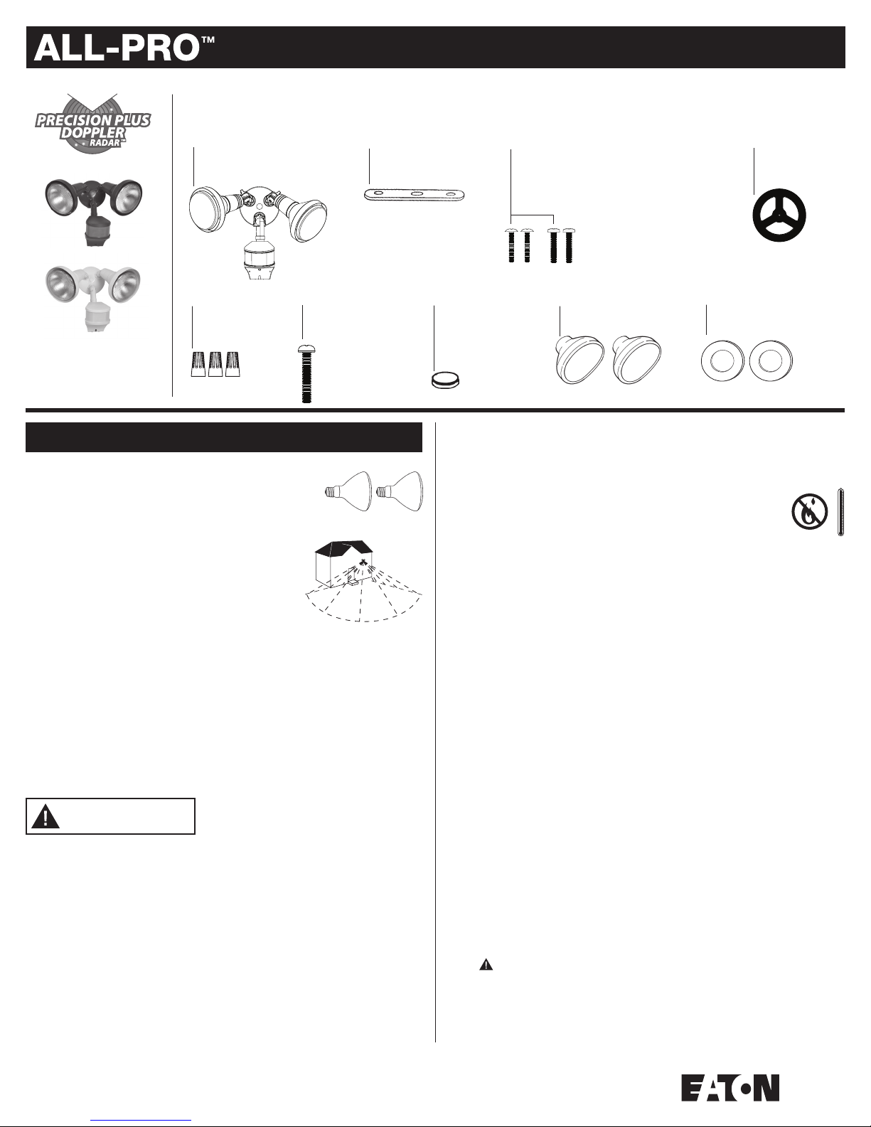
PACKAGING CONTENTS/ CONTENIDO DEL PAQUETE
A. Motion detector and light fixture
Detector de movimiento y
artefacto de luz
B. Mounting bracket
Soporte de montaje
Instruction Manual/Instrucciones
C. (2) #6 and (2) #8 mounting screws
(use the size that fits your junction box)
(2) Tornillos #6 y (2) tornillos #8 de montaje
(utilice el tamaño que mejor se adecue
a su caja de conexión)
D. Coverplate gasket
Junta de la placa
de cubierta
E. (3) Wire nuts
(3) Tuercas para
alambre
F. Mounting plate screw
Tornillo para la placa
de montaje
MS276RD (Bronze)
MS276RDW (White)
ENGLISH
ITEMS REQUIRED
(Purchase separately)
• Phillips screwdriver
• Outdoor weatherproof silicone caulking
• (2) 150 watt (MAX) PAR 38 floodlight bulbs
HOW IT WORKS
PIR does a good job of detecting lateral motion across the 270°
range of detection. Precision Plus Doppler Radar™ does an
excellent job detecting motion towards and away from the unit.
Both systems combined provide enhanced accuracy and complete
coverage within the detection range. Motion from any direction
will trigger your floodlight—even during hot or cold temperature
extremes.
270 degrees
Up to
90 feet
IMPORTANT SAFETY INSTRUCTIONS
When using product, basic precautions should always be followed, including the following:
• Heed all warnings, including below warnings AND those included on product.
• Save these instructions and warnings.
• For outdoor use only.
• cULus LISTED for wet location.
• Disassembly of your fixture will void the warranty.
• Your fixture is prewired and preassembled for easy installation.
WARNING
• Read and follow these instructions.
• To reduce the risk of a burn during relamping, disconnect power supply to the unit
before relamping.
• Bulb gets HOT quickly!
• The bulb and fixture get extremely hot during use. Disconnect power and allow fixture
to cool before changing bulb or handling fixture.
• Always replace bulb with the same wattage or lower wattage than marked. Installing
a bulb of a higher wattage could create a fire hazard. Use of a higher wattage bulb
will void the warranty. (Maximum 150 watt halogen bulb.) To meet ENERGY STAR
requirements, maximum lamp wattage cannot exceed 250 watts.
CAUTION
• Connect fixture to a 120 volt, 60 Hz power source. Any other connection voids
the warranty.
• Fixture mounts to a recessed standard grounded junction box marked for use in wet
locations.
®
G. Color-matched
center hole plug
Tapón para agujero
central de color
coincidente
• Fixture should be installed by persons with experience in household wiring or by a
qualified electrician. The electrical system, and the method of electrically connecting
the fixture to it, must be in accordance with the National Electrical Code and local
building codes.
• Do not allow sensor head to touch light housing – maintain at least 1 inch space
between fixture and sensor.
• Keep away from flammable objects. Do not position fixture within
two inches of any combustible materials.
• MINIMUM 90°C SUPPLY CONDUCTORS.
• For proper operation and protection against damage, the motion sensor head
adjustment knobs must be facing the ground.
• Do not use this apparatus near water.
• Clean only with a dry cloth.
• Do not block any ventilation openings. Install in accordance with the manufacturer’s
instructions.
• Do not install near any heat sources such as radiators, heat registers, stoves or other
apparatus (including amplifiers) that produce heat.
• Only use attachments/accessories specified by the manufacturer.
• If lens is replaced, use only tempered safety glass of equal thickness per
UL requirements.
• This device complies with Part 15 of the FCC Rules. Operation is subject to the
following two conditions: (1) This device may not cause harmful interference, and (2)
this device must accept any interference received, including interference that may cause
undesired operation. Under Part 15 of the FCC Rules, any changes or modifications to
the motion detector described in this instruction sheet that are not expressly approved
by Eaton could void the user’s authority to operate the equipment.
NOTE: This equipment has been tested and found to comply with the limits for
a Class B digital device, pursuant to Part 15 of the FCC Rules. These limits are
designed to provide reasonable protection against harmful interference in a
residential installation. This equipment generates, uses and can radiate radio
frequency energy and if not installed and used in accordance with the instructions,
may cause harmful interference to radio communications. However, there is no
guarantee that interference will not occur in a particular installation. If this equipment
does cause harmful interference to radio or television reception, which can be
determined by turning the equipment off and on, the user is encouraged to try to
correct the interference by one or more of the following measures:
- Reorient or relocate the receiving antenna.
- Increase the separation between the equipment and receiver.
- Connect the equipment into an outlet on a circuit different from that to which the
receiver is connected.
- Consult the dealer or an experienced radio/TV technician for help.
modifications to this equipment not expressly approved by the manufacturer
could void the user’s authorization to operate this equipment.
SAVE THESE INSTRUCTIONS.
WARNING: FCC Regulations state that any unauthorized changes or
H. (2) Light covers
(2) Cubiertas de las luces
I. (2) Lampholder gaskets
(2) Juntas para portalámpara
1
FOR BEST RESULTS
• Install the motion sensor/transmitter 8-12 feet above
ground (motion sensor is less sensitive above 12 feet).
• Locate motion sensor so motion moves laterally or
towards the detection zone (Fig. 1).
• Locate sensor away from heat producing sources to
prevent false triggering. Also be very careful not to
include objects such as windows, white walls and
water in the detection zone.
• Locate fixture away from moving objects such as
trees, large shrubs and street traffic.
• Do not install more than one motion activated
floodlight on one wall switch.
MOUNTING YOUR FIXTURE
NOTE: Universal coverplate mounts to recessed standard
grounded junction boxes (Fig. 2). Junction box must be
at least 1-1/2 inch in depth for proper installation.
NOTE: For best performance when installing more than
one Precision Plus Doppler Radar™ fixture:
• Two or more units mounted side by side (facing the
same direction) should be at least 17 feet apart.
• Two units facing each other should be mounted at
least 100 feet apart.
• Fixture can be wall or eave mounted (Fig. 3).
WARNING: Risk of electric shock. Disconnect
power at fuse or circuit breaker before installing
or servicing.
1. Line up the holes on the mounting bracket (B) with
the holes on your junction box. Using either (2) #6
screws or (2) #8 screws (C) (depending on the size
of the holes in your junction box), attach the mounting
bracket (B) to your junction box (Fig. 4).
2. Thread fixture wires through coverplate gasket (D).
3. Position the gasket (D) on the coverplate and connect
the black wire from the fixture (A) to the black house
supply wire and the white wire from the fixture (A)
to the white supply wire using the wire nuts (E)
provided. Attach the ground wire coming from your
house to the copper ground wire from the fixture (A)
using wire nut (E) provided. If no house ground wire
is available, attach the copper ground wire from
the fixture (A) to the junction box if it is metal and
grounded. If junction box is not metal and no house
ground wire is available, an alternative ground
source must be used for safe operation (Fig. 5).
4. Attach fixture (A) to the mounting bracket (B)
using the mounting plate screw (F) provided.
Be sure no loose wires remain sticking out from
underneath the coverplate. Insert plastic colormatched (G) plug in mounting plate screw hole
for finished appearance (Fig. 6).
5. Apply silicone caulking around edges of coverplate and
in any open holes to provide a watertight seal from
rain and moisture.
6. Install protective lamp covers (H) onto lampholders
by lining up the nipples on the covers (H), over the
lampholder slots. Lock into place by twisting covers
counterclockwise (Fig. 7).
7. Insert gaskets (I) into lampholders and screw
bulbs into each lampholder (Fig. 8). (Do not over
tighten bulbs.)
8. Turn power on at main fuse/breaker box.
AIMING THE LIGHT
Loosen the knob on the side of the lampholder.
Tilt lampholder up or down to desired position, then
retighten knob.
WARNING: Deviation from the assembly
instructions may result in a risk of electric shock.
OPERATING YOUR FIXTURE
1. Turn the arrow on the MODE knob to “TEST” for test
mode (Fig. 9).
2. Turn the arrow on the SENSITIVITY knob to a middle
point between “+” and “–”.
1
2
1-1/2 in.
Round
1-1/2 in.
Octagonal
3
Wall mount Eave mount
4
C
B
C
5
E
E
E
D
A
6
F
A
G
7
H
8
A
H
H
I
9
3. Turn on the power to the fixture (A). Allow fixture to warm up approximately 90 seconds
before testing. (Lights may or may not come on during warm-up period; this is normal.)
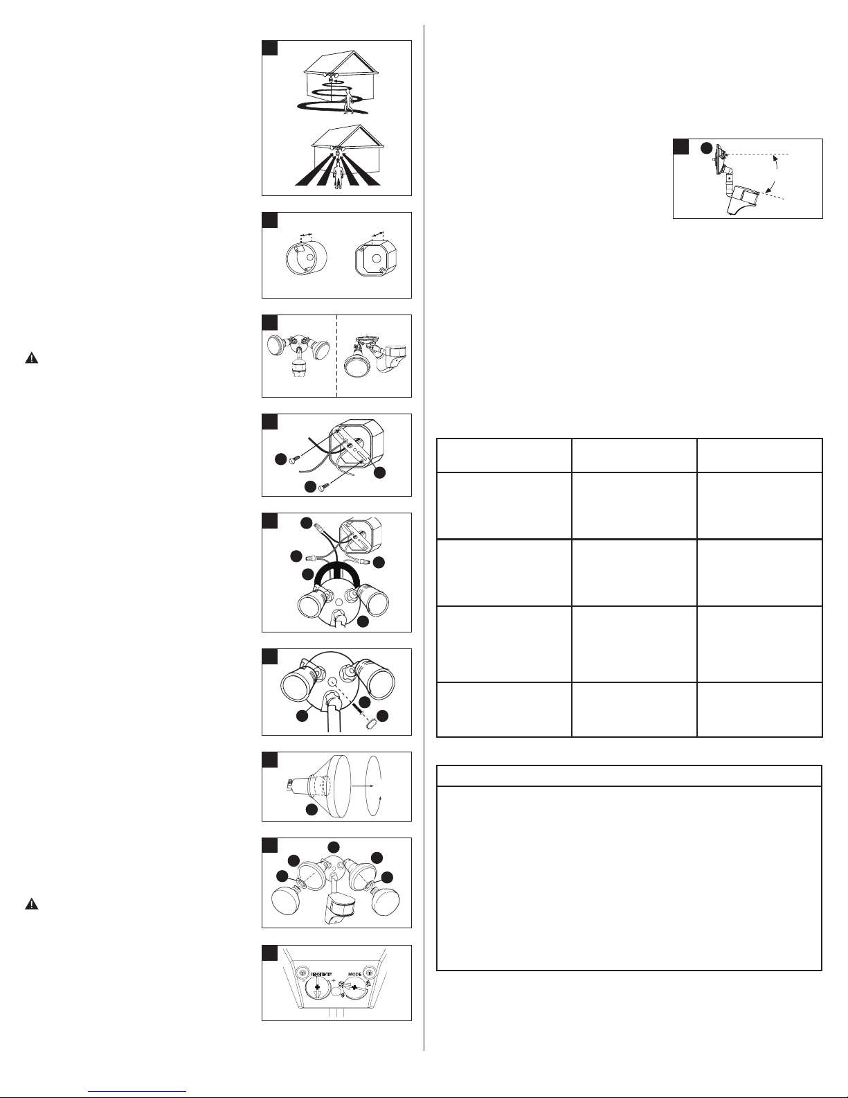
4. Aim sensor toward the general direction that motion will be coming from. Maintain at least
1 inch of clearance between sensor head and lamps. Always position the sensor head with
control switches facing toward the ground.
NOTE: (Sensor Head Placement) For optimum detection, you may have to experiment with
aiming and settings. Each location will be different and your terrain may affect the angle your
sensor needs. Adjusting the angle will change your area of detection. Here are some general
guidelines to help with setup:
• 8 ft.–12 ft. above the ground is a good range for
the placement of your fixture.
• For an 8 ft. mounting height, placing the sensor at
a 5° angle below horizontal should work well for
10
A
5°
most locations (Fig. 10).
• If the fixture is mounted higher, the angle of the
sensor below horizontal should increase.
5. Walk through the detection zone at the farthest distance you want your detector to
detect motion.
6. Adjust the SENSITIVITY knob until you get desired results. For more range, aim sensor
slightly upward. For less range, aim sensor head slightly downward. Lights will turn off
4 seconds after motion stops.
7. Adjust the “Auto” MODE knob to a time selection from 1m-12m, depending on how many
minutes you want the fixture to stay on after motion is detected. At dusk, the photo control
will activate your fixture to operate according to the settings chosen.
NOTE: Decreasing the SENSITIVITY will decrease the distance the unit can detect.
NOTE: During daylight hours, the red LED indicator light will flash when motion is detected.
This is normal.
Maximum lamp wattage cannot exceed 250 watts.
SELECTING YOUR DESIRED FEATURE
Mode of MODE Knob How to Set
Operation Adjustment Power Switch
Test Setting
Lights should turn ON with
motion both day and night.
Lights should turn OFF
after 4 seconds.
Motion Activated Setting “Auto”
Lights should turn on with
motion only at night and
should turn OFF after
1-12 min. of no motion.
Dusk-to-Dawn Setting
(activated only at night)
Lights should stay on from
dusk to dawn and then reset
to motion activated
setting at the next dawn.
Return to
Motion Activated Setting
from any of
the above settings.
MODE knob arrow
points to TEST.
“Auto” MODE knob arrow
points to a time
selection within the
1m-12m time range.
MODE knob arrow
points to a time selection
within the 1m-12m
time range.
“Auto” MODE knob arrow
points to a time selection
within the 1m-12m
time range.
Wall Switch Setting
(connected to fixture)
Keep wall switch
in ON position.
Keep wall switch in
ON position.
Keep the power
to the fixture ON.
Turn the power
OFF-ON-OFF-ON
within 3 seconds; light will
go into override mode.
Turn the power OFF
for at least 90 seconds
and then back ON.
TROUBLESHOOTING
Problem Cause / Solution
Lights do not
come ON with
motion at night.
I
No power to the fixture.
• Check if circuit breaker tripped.
• Confirm wall switch is ON.
Bulb is faulty.
• Replace bulb.
Surrounding external ambient light is too bright. (If so, the unit may
think it is daytime.)
• Re-aim the head.
• Relocate or reposition the unit away from the light.
TURN OFF POWER BEFORE CONTINUING
Wiring to the unit is loose.
• Check wiring, and reconnect if necessary using wire
nuts (E) provided.
2
 Loading...