

Eaton All-Pro MS245RW, All-Pro MS245R Instruction Manual
Questions?/Des questions?/¿Preguntas? 1-800-334-6871 ConsumerProducts@eaton.com
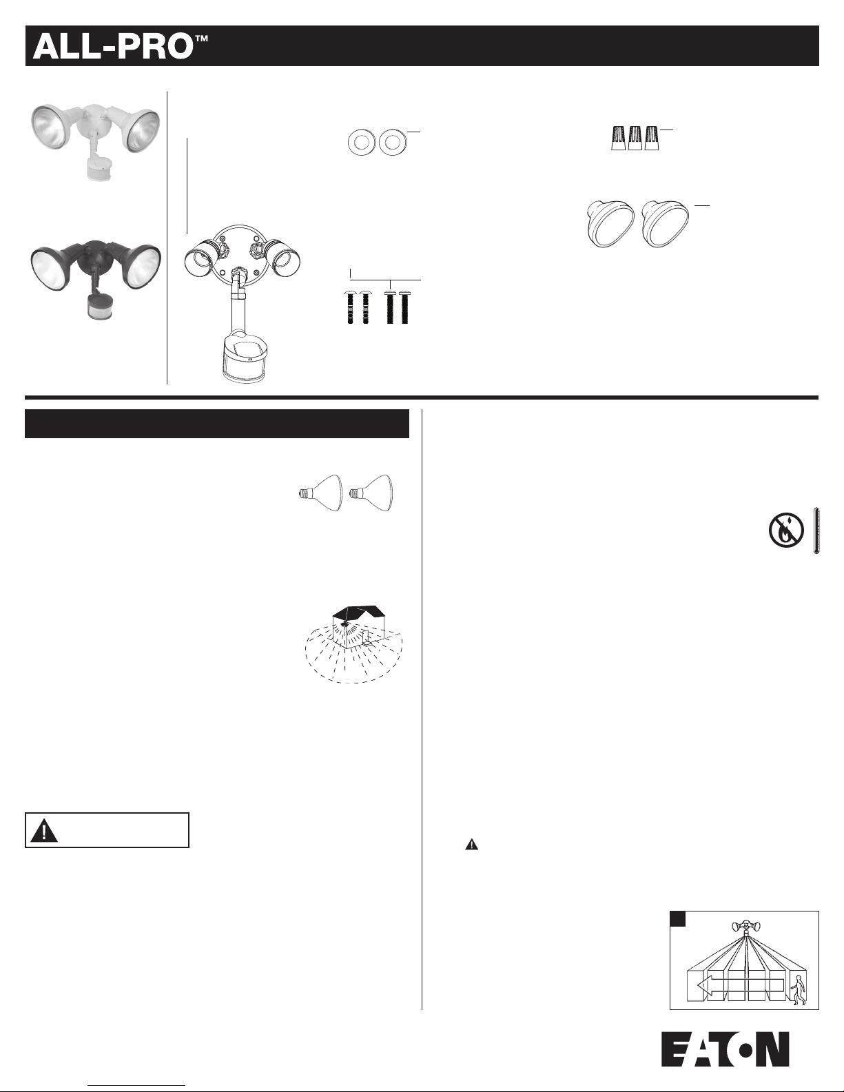
PACKAGING CONTENTS/ CONTENU DE L’EMBALLAGE/ CONTENIDO DEL PAQUETE
A. Motion detector
and light fixture
Detector de movimiento
y accesorio
Luminaire avec détecteur de
mouvement
MS245RW (White)
MS245R (Bronze)
ENGLISH
ITEMS REQUIRED
(Purchase separately)
• Phillips screwdriver
• Outdoor weatherproof silicone caulking
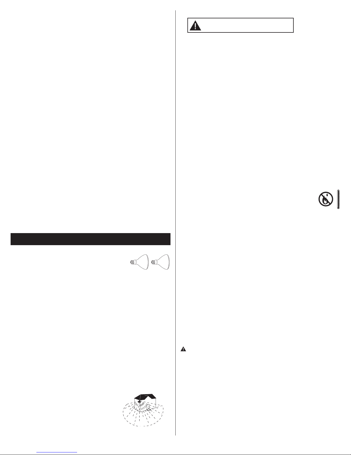
• (2) 100 watt (MAX) PAR 38 floodlight bulbs
NOTE: This fixture was designed to work with up to 150 watt maximum PAR halogen flood
bulbs. For improved energy efficiency, lower wattage PAR halogen flood bulbs may be used.
Compact Fluorescent (CFL) bulbs contain electronics which may interfere with the motion
sensing function of your fixture and are not recommended. To meet ENERGY STAR
requirements, maximum lamp wattage can not exceed 250 watts.
HOW IT WORKS
Your motion activated floodlight senses heat images from
objects such as people, large animals and automobile engines.
When motion is detected, the lights will automatically turn
on. Once motion has stopped, the lights will turn off after a
preselected time delay. Your motion activated floodlight may
also be used as a standard floodlight.
IMPORTANT SAFETY INSTRUCTIONS
When using product, basic precautions should always be followed, including the following:
• Heed all warnings, including below warnings AND those included on product.
• Save these instructions and warnings.
• For outdoor use only.
• cULus LISTED for wet location.
• Disassembly of your fixture will void the warranty.
• Your fixture is prewired and preassembled for easy installation.
®
Up to
70 feet
270 degrees
WARNING
• Read and follow these instructions.
• To reduce the risk of a burn during relamping, disconnect power supply to the unit
before relamping.
• Bulb gets HOT quickly!
• Always replace bulb with the same wattage or lower wattage than marked. Installing
a bulb of a higher wattage could create a fire hazard. Use of a higher wattage bulb
will void the warranty (maximum 150 watt halogen bulb).
CAUTION
• Connect fixture to a 120 volt, 60 Hz power source. Any other connection voids
the warranty.
• Mount fixture to a grounded, recessed-mounted standard junction box marked for use
Instruction Manual/Instrucciones
B. (2) Lampholder gaskets
(2) Juntas obturadoras
del receptáculo
(2) Joints statiques de douille
D. (2) #6 and (2) #8 mounting screws
(use the size that fits your junction box)
(2) Tornillos #6 y (2) tornillos #8 de montaje (utilice el
tamaño que mejor se adecue a su caja de conexión)
(2) vis nº6 et (2 )vis nº8 pour boîte de jonction (choisissez
la dimension convenant à votre boîte de jonction)
in wet locations.
• Suitable for wall mount or eave mount only. NOT suitable for ground mount installation.
• Fixture should be installed by persons with experience in household wiring or by a
qualified electrician. The electrical system, and the method of electrically connecting
the fixture to it, must be in accordance with the National Electrical Code and local
building codes.
• Do not allow sensor head to touch light housing – maintain at least
1 in. space between fixture and sensor.
• Keep away from flammable objects. Do not position fixture within 2 in.
of any combustible materials.
• MINIMUM 90°C SUPPLY CONDUCTORS.
• For proper operation and protection against damage, the motion sensor head
adjustment knobs must be facing the ground.
• This device complies with Part 15 of the FCC Rules. Operation is subject to the
following two conditions: (1) This device may not cause harmful interference, and (2)
this device must accept any interference received, including interference that may cause
undesired operation. Under Part 15 of the FCC Rules, any changes or modifications to
the motion detector described in this instruction sheet that are not expressly approved
by Eaton could void the user’s authority to operate the equipment.
NOTE: This equipment has been tested and found to comply with the limits for
a Class B digital device, pursuant to Part 15 of the FCC Rules. These limits are
designed to provide reasonable protection against harmful interference in a
residential installation. This equipment generates, uses and can radiate radio
frequency energy and if not installed and used in accordance with the instructions,
may cause harmful interference to radio communications. However, there is no
guarantee that interference will not occur in a particular installation. If this
equipment does cause harmful interference to radio or television reception, which
can be determined by turning the equipment off and on, the user is encouraged to
try to correct the interference by one or more of the following measures:
- Reorient or relocate the receiving antenna.
- Increase the separation between the equipment and receiver.
- Connect the equipment into an outlet on a circuit different from that to which the
receiver is connected.
- Consult the dealer or an experienced radio/TV technician for help.
WARNING: FCC Regulations state that any unauthorized changes or
modifications to this equipment not expressly approved by the manufacturer
could void the user’s authorization to operate this equipment.
SAVE THESE INSTRUCTIONS.
FOR BEST RESULTS
• Install the motion sensor/transmitter 8-12 feet
above the ground. (Motion sensor is less sensitive
above 12 feet.)
• Locate motion sensor so motion moves across
detection zone (Fig. 1).
• Locate sensor away from heat producing sources to
C. (3) Wire nuts
(3) Conectores del cables
(3) Capuchons de connexion
E. (2) Reflectors
(2) Reflectores
(2) réflecteurs
1
1
prevent false triggering. Also be very careful not to
include objects such as windows, white walls and
2
1-1/2 in.
1-1/2 in.
water in the detection zone.
• Locate sensor away from moving objects such as
trees, large shrubs and street traffic.
MOUNTING AND WIRING YOUR FIXTURE
WARNING: Risk of electric shock. Disconnect
power at fuse or circuit breaker before installing
or servicing.
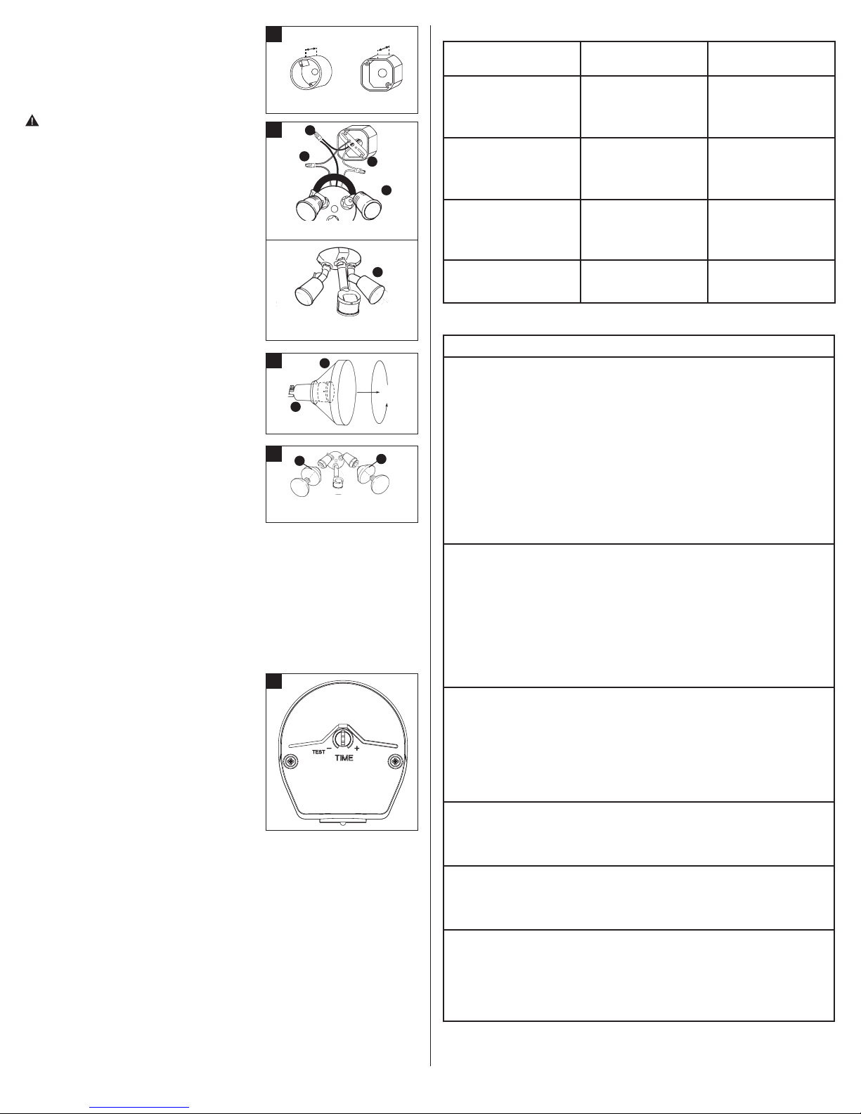
NOTE: Coverplate mounts to recessed mounted
Round
3
C
C
Octagonal
C
standard junction boxes (Fig. 2). Junction box must be
at least 1-1/2 inch in depth for proper installation for
recessed mount application.
A
1. This coverplate has been designed to work with a
variety of different junction boxes (not included).
Wall mount
Line up the holes in the coverplate with the screw
bosses in your junction box.
NOTE: If holes in the coverplate do not match the
screw holes on your junction box, drill holes in the
A
coverplate using an 3/16 inch drill bit to match the
screw holes on the junction box.
2. Connect the black wire from the fixture to the
black house supply wire and the white wire
Eave mount
from the fixture to the white supply wire using
wire nuts (C) (Fig. 3).
3. Attach the ground wire coming from your house
4
E
to the copper ground wire from the fixture (A) using
wire nut (C) (Fig. 3). If no house ground wire is
available, attach the copper ground wire from the
A
fixture to the junction box if it is metal and
grounded. If junction box is not metal and no house
ground wire is available, an alternative ground
source must be used for safe operation.
5
B
B
4. Attach fixture to the junction box with two of the
screws (D) provided. Either (2) #6 or (2) #8 screws
will work with most standard junction boxes. Make
sure that all screws are tightly secured.
5. To prevent moisture from entering the junction box, apply a bead of silicone sealant
around the edge of the coverplate where it attaches to the junction box and any open
holes.
6. Install protective reflectors (E) onto lampholders by lining up the nipples on the covers,
over the lampholder slots. Lock into place by twisting covers counterclockwise (Fig. 4).
7. Insert lampholder gaskets (B) into lampholder assembly, tightly against lampholder, and
screw bulbs into each lampholder (Fig. 5). (Do not overtighten bulbs.)
8. Turn on power at main fuse/breaker box.
OPERATING YOUR FIXTURE
1. Set dial to “TEST” (Fig. 6).
2. Turn on the power to fixture. Allow fixture to warm
up approximately 40 seconds before testing.
3. Aim sensor head toward desired detection area,
maintaining a 5° down angle to allow
moisture to drain.
NOTE: Maintain at least 1 inch of air space between
lamps and sensor head. Make sure sensor
head is positioned with control switches facing to
wards the ground.
4. Walk across the detection zone at the farthest
distance you wish your detector to detect motion.
5. Adjust sensor head angle until you get desired
results.
NOTE: For maximum range performance, allow fixture to operate in any mode (with power to
the unit) for at least 48 hours.
6. Set dial to desired time setting. The higher the time setting, the longer the lamps will be
ON. (Maximum time is 12 minutes.)
6
SELECTING YOUR DESIRED FEATURE
Mode of MODE Knob How to Set
Operation Adjustment Power Switch
Auto Setting (motion activated)
Lights should turn ON with
motion only at night and should
turn OFF according to the
TIME dial setting.
Dusk to Dawn Setting
(activated only at night)
Lights should turn ON for 6 hours
at dusk and then reset to
the Auto Setting.
Test Setting
Lights should turn ON with
motion both day and night.
Lights should turn OFF
after 4 seconds.
Return to Auto Setting
(motion activated)
From any of the above settings
Knob arrow points to
desired time setting
within TIME range.
Knob arrow points to
desired time setting
within TIME range.
TEST
Knob arrow points to
desired time setting
within TIME range.
Turn the power
to the fixture ON.
Turn the power
OFF and ON twice
within 3 seconds.
Turn the power
to the fixture ON.
Turn the power OFF
for at least 40 seconds
and then back ON.
TROUBLESHOOTING
Problem Cause / Solution
Light does not
come ON with
motion at night.
Light comes ON
for no apparent
reason at night.
Light stays ON at
night and does
not turn OFF.
Light
continuously
blinks ON and
OFF at night.
Light is ON
during the day.
Cannot activate
dusk to dawn
mode at night
(override)
No power to the fixture.
• Check if circuit breaker tripped.
• Confirm wall switch is ON.
Bulb is faulty.
• Replace bulb.
Surrounding external ambient light is too bright. (If so, the unit may
think it is daytime.)
• Re-aim the head.
• Relocate or reposition the unit away from the light.
TURN OFF POWER BEFORE CONTINUING
Wiring to the unit is loose.
• Check wiring; reconnect if necessary using wire nuts
(E) provided.
There is motion in the detection zone.
• Make sure the sensor is not picking up moving objects such as
trees, traffic, etc.
TEST FOR YOURSELF.
• Cover the sensor lens with cardboard to prevent sensor from
detecting motion. If the light stays off, something in the detection
zone is triggering the sensor.
* If the light stays on with the sensor lens covered, contact
customer service.
• Reposition the sensor.
There is motion in the detection zone.
• Make sure the sensor is not picking up moving objects such as
trees, traffic, etc.
• Reposition the sensor.
Unit is in Dusk to Dawn setting (if there is no motion).
• Turn the light switch to the OFF position for 40 seconds, and
then turn back to the ON position. This will send the unit back
into the “Auto” mode.
The light given from the unit’s own lamp is affecting the
motion sensor.
• Re-aim the lamp.
• Reposition motion sensor.
The controls on the bottom of the motion sensor are in “TEST” mode.
• Change dial setting (not “TEST” mode).
The motion detector is shadowed.
• Reposition motion sensor.
Surrounding external ambient light is too bright. (If so, the unit may
think it is daytime.)
• Re-aim the head.
• Relocate or reposition the unit away from the light.
Not enough time is allowed to enter the dusk to dawn mode.
• Turn power OFF and ON twice within 3 seconds.
2
3-YEAR LIMITED WARRANTY
THE FOLLOWING WARRANTY IS EXCLUSIVE AND IN LIEU OF ALL OTHER WARRANTIES,
WHETHER EXPRESS, IMPLIED OR STATUTORY INCLUDING, BUT NOT LIMITED TO, ANY
WARRANTY OF MERCHANTABILITY OR FITNESS FOR ANY PARTICULAR PURPOSE.
Eaton warrants to customers that, for a period of three years from the date of purchase, Eaton
products will be free from defects in materials and workmanship. The obligation of Eaton
under this warranty is expressly limited to the provision of replacement products. This
warranty is extended only to the original purchaser of the product. A purchaser’s receipt or
other proof of date of original purchase acceptable to Eaton. This is required before warranty
performance shall be rendered.
This warranty does not apply to Eaton products that have been altered or repaired or that
have been subjected to neglect, abuse, misuse or accident (including shipping damages). This
warranty does not apply to products not manufactured by Eaton which have been supplied,
installed, and/or used in conjunction with Eaton products. Damage to the product caused by
replacement bulbs or corrosion or discoloration of brass components are not covered by this
warranty.
LIMITATION OF LIABILITY:
IN NO EVENT SHALL EATON BE LIABLE FOR SPECIAL, INDIRECT, INCIDENTAL, OR
CONSEQUENTIAL DAMAGES (REGARDLESS OF THE FORM OF ACTION, WHETHER IN CONTRACT,
STRICT LIABILITY, OR IN TORT INCLUDING NEGLIGENCE), NOR FOR LOST PROFITS; NOR SHALL
THE LIABILITY OF EATON FOR ANY CLAIMS OR DAMAGE ARISING OUT OF OR CONNECTED WITH
THESE TERMS OR THE MANUFACTURE, SALE, DELIVERY, USE, MAINTENANCE, REPAIR OR
MODIFICATION OF EATON PRODUCTS, OR SUPPLY OF ANY REPLACEMENT PARTS THEREFORE,
EXCEED THE PURCHASE PRICE OF EATON PRODUCTS GIVING RISE TO A CLAIM. NO LABOR
CHARGES WILL BE ACCEPTED TO REMOVE OR INSTALL FIXTURES.
To obtain warranty service, please contact Eaton at 1-800-334-6871, press
option 2 for Customer Service, or via e-mail ConsumerProducts@eaton.com and include the
following information:
• Name, address and telephone number
• Date and place of purchase
• Catalog and quantity purchase
• Detailed description of problem
All returned products must be accompanied by a Return Goods Authorization Number issued
by the Company and must be returned freight prepaid. Any product received without a Return
Goods Authorization Number from the Company will be refused.
Eaton is not responsible for merchandise damaged in transit. Repaired or replaced products
shall be subject to the terms of this warranty and are inspected when packed. Evident or
concealed damage that is made in transit should be reported at once to the carrier making the
delivery and a claim filed with them.
Reproductions of this document without prior written approval of Cooper Lighting, LLC are strictly prohibited.
For assistance, call 1-800-334-6871 or e-mail us at ConsumerProducts@eaton.com.
Printed in China
FRENCH
ARTICLES REQUIS
(à acheter séparément)
• Tournevis à tête cruciforme
• Calfeutrant résistant aux intempéries en silicone pour extérieur
• (2) ampoules pour projecteurs PAR 38 de 100 W (MAX.)
REMARQUE : Ce luminaire a été conçu pour fonctionner avec des ampoules de projecteur PAR
de 150watts maximum. Pour améliorer l’efficacité énergétique, vous pouvez utiliser des ampoules halogènes PAR d’une puissance inférieure. Les ampoules fluocompactes contiennent
des composants électroniques qui pourraient nuire aux fonctions de détection de mouvement
et de lumière de votre luminaire et ne sont pas recommandées.
FONCTIONNEMENT
PIR Le détecteur infrarouge passif est efficace pour détecter les mouvements latéraux avec
une portée de détection de 180°. Le système Precision Plus Doppler RadarMC détecte très
efficacement les mouvements éloignés à l’avant de l’appareil. Ces deux systèmes combinés
offrent une précision accrue et une couverture complète à l’intérieur de la portée de détection.
Un mouvement provenant de toute direction déclenchera l’allumage du projecteur, même
lorsque la température est extrêmement chaude ou froide.
INSTRUCTIONS DE SÉCURITÉ IMPORTANTES
Lors de l’utilisation d’un produit, des précautions de base doivent être respectées y compris
les suivantes :
• Respectez tous les avertissements incluant les avertissements ci-dessous ET ceux
indiqués sur le produit.
• Conservez ces instructions et ces avertissements.
• Pour utilisation à l’extérieur seulement.
• Homologation cULus pour l’utilisation dans des endroits
humides.
• Le démontage du luminaire annule la garantie.
Jusqu’à
70 pieds
270 degrés
• Le luminaire est câblé et assemblé pour faciliter son installation.
AVERTISSEMENT
• Lisez et suivez ces instructions.
• Mettez l’alimentation électrique du luminaire hors tension avant de changer l’ampoule
afin de réduire le risque de brûlure.
• L’ampoule devient CHAUDE rapidement!
• L’ampoule et le luminaire deviennent extrêmement chauds lors de l’utilisation. Mettez
l’alimentation électrique hors tension et laissez refroidir le luminaire avant de le
manipuler ou de changer l’ampoule.
• Remplacez toujours une ampoule par une ampoule de puissance égale ou inférieure
à celle marquée. L’utilisation d’une ampoule de puissance supérieure représente
un risque d’incendie. L’utilisation d’une ampoule ayant une puissance supérieure
annulera la garantie (ampoule halogène de 150 W max.). La puissance d’une ampoule
ne doit pas excéder un maximum de 150 W afin de répondre aux exigences ENERGY
STAR®.
MISE EN GARDE
• Raccordez le luminaire à une source d’alimentation de 120V, 60Hz. Tout autre
raccordement annule la garantie.
• Raccordez le luminaire à une boîte de jonction encastrée et mise à la terre classique
et marquée pour une utilisation dans des endroits humides.
• Convient uniquement à une installation murale ou sur un avant-toit. NE convient PAS à
une installation au sol.
• Le luminaire doit être installé par des personnes ayant l’expérience du câblage
domestique ou par un électricien qualifié. Le système électrique et la méthode de
raccordement électrique du luminaire doivent être conformes au Code national de
l’électricité et au Code du bâtiment local.
• Évitez tout contact de la tête du détecteur avec le boîtier du luminaire - maintenez un
espace d’au moins 2,5 cm (1 po) entre le luminaire et le détecteur.
• Tenez le luminaire à l’écart des objets inflammables. Ne placez pas le luminaire à
moins de 5 cm (2 po) de matériaux combustibles.
• CONDUCTEURS D’ALIMENTATION DE 90 °C MIN.
• Pour assurer le fonctionnement et la protection contre les dégâts, il faut
diriger les boutons de réglage du détecteur de mouvements vers le sol.
• Only use attachments/accessories specified by the manufacturer.
Ce dispositif est conforme à la section 15 des règlements de la FCC. Son fonctionnement est assujetti aux deux conditions suivantes: 1)cet appareil ne doit pas
provoquer d’interférences nuisibles et 2)cet appareil doit accepter toutes les interférences reçues, même celles qui pourraient provoquer un fonctionnement indésirable.
Conformément à la section 15 des règlements de la FCC, toute modification ou altération apportées au détecteur de mouvements décrit dans les présentes instructions et
non approuvées explicitement par Eaton peut annuler le droit de l’utilisateur à faire
fonctionner l’équipement.
REMARQUE : Après la mise à l’essai, cet équipement a été déclaré conforme aux
limites établies pour un dispositif numérique de catégorieB en vertu de la
section 15 des règlements de la FCC. Ces limites sont conçues pour assurer une
protection raisonnable contre tout brouillage nuisible dans une installation
résidentielle. Cet équipement produit, utilise et peut émettre des ondes
radioélectriques. S’il n’est pas installé et utilisé conformément aux instructions, il
peut créer des parasites nuisibles aux communications radio. Cependant, il n’existe
aucune garantie que les interférences ne se produiront pas avec une installation
particulière. Si cet équipement cause des parasites nuisibles à la réception radio
ou d’émissions de télévision, ce qui peut être vérifié en éteignant l’équipement et
en le rallumant, il est conseillé à l’utilisateur d’essayer de les éliminer en suivant l’une
(ou plusieurs) des mesures suivantes :
Réorientez ou déplacez l’antenne réceptrice.
- Augmentez la distance entre l’équipement et le récepteur.
- Branchez l’équipement sur la prise électrique d’un circuit autre que celui sur lequel
le récepteur est branché.
- Demandez de l’aide au distributeur ou à un technicien radio ou TV qualifié.
AVERTISSEMENT : Les réglementations de la FCC mentionnent que toute modifica-
tion et altération apportées à cet équipement n’étant pas expressément approuvée par
le fabricant peut annuler le droit de l’utilisateur à faire fonctionner cet équipement.
CONSERVEZ CES INSTRUCTIONS.
POUR DES RÉSULTATS OPTIMAUX
• Installez le détecteur de mouvements ou le
transmetteur de 2,4 m à 3,7 m (8 à 12 pi)
audessus du sol (Le détecteur de mouvements est
moins sensible au-dessus de 3,7m ou 12pi.)
• Placez le détecteur de mouvements de manière à ce
qu’il repère les mouvements dans toute la zone de
détection (Fig. 1).
• Choisissez un emplacement éloigné des sources de chaleur afin d’éviter les faux
3
 Loading...