

Eaton FP-25-LV-VSR, AK-2A-25-LV-VSR-425A, AK-2-25-LV-VSR-425A, AK-3A-25-LV-VSR-425A Instruction Book

Instruction Book IB019008EN
Effective
FP-25-LV-VSR
Breaker-To-Motor Starter Conversion
October 2016
FP-25-LV-VSR 425A Shown

FP-25-LV-VSR
Breaker-To-Motor Starter Conversion
DISCLAIMER OF WARRANTIES AND LIMITATION OF LIABILITY
The information, recommendations, descriptions and safety notations in this document are based on Eaton’s experience and judgment and
may not cover all contingencies. If further information is required, an Eaton sales office should be consulted. Sale of the product shown in
this literature is subject to the terms and conditions outlined in appropriate Eaton selling policies or other contractual agreement between
Eaton and the purchaser.
THERE ARE NO UNDERSTANDINGS, AGREEMENTS, WARRANTIES, EXPRESSED OR IMPLIED, INCLUDING WARRANTIES OF FITNESS
FOR A PARTICULAR PURPOSE OR MERCHANTABILITY, OTHER THAN THOSE SPECIFICALLY SET OUT IN ANY EXISTING CONTRACT
BETWEEN THE PARTIES. ANY SUCH CONTRACT STATES THE ENTIRE OBLIGATION OF EATON. THE CONTENTS OF THIS DOCUMENT
SHALL NOT BECOME PART OF OR MODIFY ANY CONTRACT BETWEEN THE PARTIES.
In no event will Eaton be responsible to the purchaser or user in contract, in tort (including negligence), strict liability or other-wise for any
special, indirect, incidental or consequential damage or loss whatsoever, including but not limited to damage or loss of use of equipment,
plant or power system, cost of capital, loss of power, additional expenses in the use of existing power facilities, or claims against the
purchaser or user by its customers resulting from the use of the information, recommendations and descriptions contained herein. The
information contained in this manual is subject to change without notice.
WARNING
IMPROPERLY INSTALLING OR MAINTAINING THESE PRODUCTS CAN
RESULT IN DEATH, SERIOUS PERSONAL INJURY, OR PROPERTY DAMAGE
READ AND UNDERSTAND THESE INSTRUCTIONS BEFORE ATTEMPTING
ANY UNPACKING, ASSEMBLY, OPERATION, OR MAINTENANCE OF THE
VACUUM STARTER REPLACEMENT.
INSTALLATION OR MAINTENANCE SHOULD BE ATTEMPTED ONLY
BY QUALIFIED PERSONNEL. THIS INSTRUCTION BOOK SHOULD NOT
BE CONSIDERED ALL INCLUSIVE REGARDING INSTALLATION OR
MAINTENANCE PROCEDURES. IF FURTHER INFORMATION IS REQUIRED,
YOU SHOULD CONSULT EATON’S ELECTRICAL SERVICES & SYSTEMS
THE VACUUM STARTER REPLACEMENTS DESCRIBED IN THIS BOOK
ARE DESIGNED AND TESTED TO OPERATE WITHIN THEIR NAMEPLATE
RATINGS. OPERATION OUTSIDE OF THESE RATINGS MAY CAUSE THE
EQUIPMENT TO FAIL, RESULTING IN DEATH, BODILY INJURY, AND
PROPERTY DAMAGE.
ALL APPLICABLE SAFETY CODES, SAFETY STANDARDS AND/OR
REGULATIONS RELATED TO THIS TYPE OF EQUIPMENT MUST BE STRICTLY
FOLLOWED.
THESE VACUUM STARTER REPLACEMENTS ARE DESIGNED TO BE
INSTALLED PURSUANT TO THE AMERICAN NATIONAL STANDARDS
INSTITUTE (ANSI) AND THE NATIONAL ELECTRICAL CODE (NEC). SERIOUS
INJURY, INCLUDING DEATH, CAN RESULT FROM FAILURE TO FOLLOW THE
PROCEDURES OUTLINED IN THIS MANUAL.
These products were manufactured by Eaton Corporation at the
Power Breaker Center: 310 Maxwell Avenue, Greenwood, SC 29646.
All possible contingencies that may arise during installation,
operation, or maintenance, and all details and variations of this
equipment do not purport to be covered by these instructions. If
further information is desired by purchaser regarding his particular
installation, operation, or maintenance of particular equipment,
contact a local Eaton representative.
2
Instruction Book IB019008EN October 2016 www.eaton.com

Table of Contents
SECTION 1: INTRODUCTION 4
1.1 AVAILABLE FP-25 -LV-VSR MOTOR STARTER REPLACEMENT 4
SECTION 2 : SAFE PRACTICES 6
SECTION 3 : RECEIVING, HANDLING, AND STOR AGE 7
3.1 RECEIVING 7
3.2 HANDLING 7
3.3 STORAGE 7
3.4 FP-25- LV-VSR APPROXIMATE WEIGHTS 7
SECTION 4: DESCRIPTION AND OPERATION 10
4.1 ELECTRICAL CONTROL 11
4.2 BUSHING AND DISCONNECTING CONTACT ASSEMBLIES 12
4.3 SECONDARY CONNECTION BLOCK 12
4.4 INTERLOCKS 12
SECTION 5: INSTALLATION & INSPECTION 13
5.1 CELL MODIFICATION INSTRUCTIONS 13
5.2 EXAMINATION FOR DAMAGE 14
5.3 ELECTRONIC OVERLOAD RELAY C4 40 15
5.4 INSERTION PROCEDURE 16
5.5 REMOVAL PROCEDURE 18
5.6 MANUAL OPERATIONAL CHECK 18
5.7 VACUUM INTEGRIT Y TEST 18
5.8 LOW FREQUENCY WITHSTAND TEST 18
5.9 CONTACT INSPECTION 18
5.10 ELECTRICAL OPERATIONAL CHECKS 18
5.11 PASSIVE INTERLOCKS 18
FP-25-LV-VSR
Breaker-To-Motor Starter Conversion
SECTION 6: INSPECTION AND MAINTENANCE 19
6.1 INTRODUCTION 19
6.2 FREQUENCY OF INSPECTION 19
6.3 INSPECTION AND MAINTENANCE PROCEDURES 19
6.4 VACUUM INTERRUPTER INTEGRIT Y TEST 20
6.5 INSULATION 20
6.6 INSULATION INTEGRITY CHECK 20
6.8 MECHANISM CHECK 21
6.9 LUBRICATION 21
6.10 PRIMARY CIRCUIT RESISTANCE CHECK 21
6.11 MAGNET OPERATING RANGE 21
SECTION 7: REPL ACEMENT OF COMPONENTS 23
7.1 GENERAL 23
Instruction Book IB019008EN October 2016 www.eaton.com
3

FP-25-LV-VSR
Breaker-To-Motor Starter Conversion
SECTION 1: INTRODUCTION
The purpose of this instruction book is to provide instructions for
receiving, handling, storage, installation, operation, and maintenance
of Type LV-VSR, Low Voltage- Vacuum Starter Replacement Units.
These units are horizontal, draw-out type removable Vacuum Starter
Replacements for existing LV Metal-Enclosed Switchgear with
breakers of the same type and rating. LV-VSRs provide reliable
control, protection, and performance, with ease of handling and
maintenance.
This booklet is intended to be used in conjunction with the technical
information provided with the original equipment order that includes
but is not limited to electrical control schematics and wiring
diagrams, installation plans, and procedures for installation and
maintenance of accessory items.
Satisfactory performance is dependant upon proper application,
correct installation, and adequate maintenance. It is strongly
recommended that this instruction book be carefully read and
followed in order to realize optimum performance and long useful life
of the LV-VSR.
The LV-VSR consists of the following components: Current Limiting
Fuses, Overload Relay, and V201 Vacuum Contactor.
•
The current limiting fuses, class J (sized as required), are primarily
used to provide short circuit protection to the vacuum contactor.
During High-Power testing, the V201 vacuum contactor was
confirmed to properly coordinate with Mersen class J AJT600EIB
current limiting fuses. The contactor successfully withstood the
let-though energy of each fuse for a 200 kA available symmetrical
fault at 600 Vac. Other UL Class J fuses can be specified by the
end user, as required, for proper coordination. Their let-through
current, however, must be less than the short circuit current
rating (SCCR) of the V201 contactor.
•
The overload relay provides longtime overload protection and
single-phase protection. The solid-state Overload Relay provides
high accuracy and enhanced protection through the use of microelectronic packaging technology. The Overload Relay comes
standard with Trip Class 10 and 20 trip characteristics and Manual
or Manual/Automatic Reset. An electro-mechanical overload relay,
Eaton type C306 may be substituted for the electronic overload
relay. This relay is equipped with Class 20 overload relay heaters
sized according to the motor full load current (FLC) and service
factor. This relay has settings to select a trip threshold closest to
the motor FLC; manual and automatic reset modes are selectable.
•
The V201 Vacuum Contactor is designed for the control of
inductive or non-inductive loads at voltages between 200 and 600,
AC.
The fuses have a micro-switch mounted to the body of the fuse that
provides blown/open indication. This switch opens the contactor and
prevents a close operation in the event of a blown/open fuse. This
feature also provides single-phase protection to the motor.
WARNING
MERSEN TYPE AOS-S MICROSWITCHES AND CURRENT LIMITING TYPE
AJT FUSES SIZED AS REQUIRED BY THE APPLICANTION MUST BE USED
TO RETAIN THE IEEE CERTIFICATION. SELECTED FUSE MUST HAVE A LETTHROUGH LESS THAN SCCR OF CONTACTOR.
1.1 Available FP-25-LV-VSR Motor Starter Replacement
Refer to Table 1.
WARNING
SATISFACTORY PERFORMANCE OF THESE VACUUM MOTOR STARTER
REPLACEMENT UNITS IS CONTINGENT UPON PROPER APPLICATION,
CORRECT INSTALLATION, AND ADEQUATE MAINTENANCE. THIS
INSTRUCTION BOOK MUST BE CAREFULLY READ AND FOLLOWED IN
ORDER TO OBTAIN OPTIMUM PERFORMANCE FOR LONG USEFUL LIFE OF
THE VACUUM MOTOR STARTER.
TYPE LV-VSR VACUUM MOTOR STARTER REPLACEMENT UNITS ARE
PROTECTIVE DEVICES, AS SUCH, THEY ARE MAXIMUM RATED DEVICES.
THEREFORE, THEY SHOULD NOT UNDER ANY CIRCUMSTANCE BE APPLIED
OUTSIDE THEIR NAMEPLATE RATINGS
ALL POSSIBLE CONTINGENCIES THAT MIGHT ARISE DURING
INSTALLATION, OPERATION, OR MAINTENANCE, AND ALL DETAILS
AND VARIATIONS OF THIS EQUIPMENT, ARE NOT COVERED BY THESE
INSTRUCTIONS. IF FURTHER INFORMATION IS DESIRED BY THE
PURCHASER REGARDING A PARTICULAR INSTALLATION, OPERATION, OR
MAINTENANCE OF THIS EQUIPMENT, THE LOCAL EATON’S ELECTRICAL
SERVICES & SYSTEMS REPRESENTATIVE SHOULD BE CONTACTED.
Table 1. FP-25-LV-VSR Vacuum Motor Starter Replacement Unit Availability and Interchangeability.
Vacuum Starter Replacement Type Rated Max. Volts
FP-25-LV-VSR-425A
4
Instruction Book IB019008EN October 2016 www.eaton.com
(VAC)
600 425 200 2200
Rated Continuous Current At
60Hz (Amps)
Rated Short Circuit kA RMS
At Rated Max. Voltage
Rated Withstand ANSI Test
Voltage Low Freq. V RMS
FP-25-LV-VSR
Breaker-To-Motor Starter Conversion
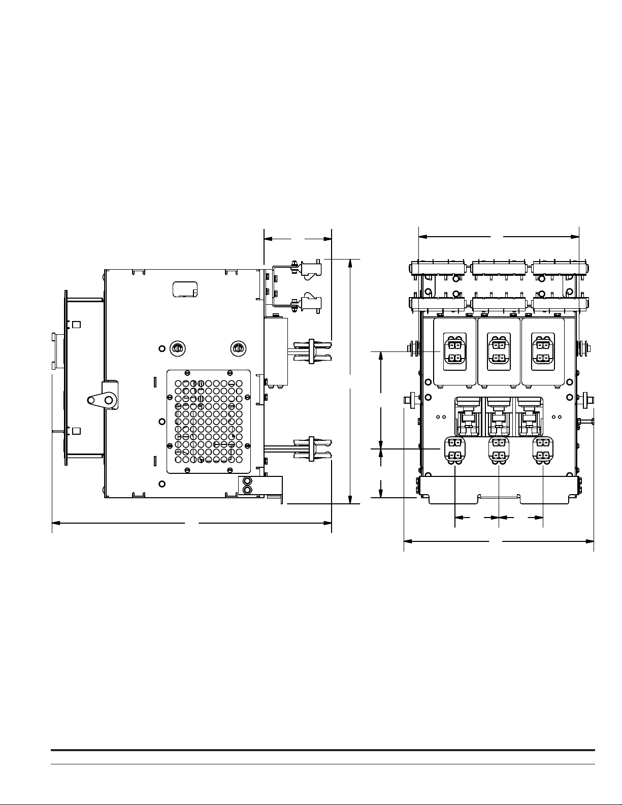
H
A
F
G
C
B
D D
Table 2. FP-25-LV-VSR Dimensions
Existing Breaker
Rated Continuous
Current at 60 Hz
Device Type
FP-25-LV-VSR
(Amps) A B C D E F G H
425A
E
5.55 4.00 8.00 3.63 15.63 13.18 20.09 23.00
Instruction Book IB019008EN October 2016 www.eaton.com
5

FP-25-LV-VSR
Breaker-To-Motor Starter Conversion
SECTION 2: SAFE PRACTICES
Vacuum Starter Replacements are designed with several built-in
interlocks and safety features to provide safe and proper operating
sequences.
WARNING
TO PROTECT THE PERSONNEL ASSOCIATED WITH INSTALLATION,
OPERATION, AND MAINTENANCE OF THE LV-VSR, THE FOLLOWING
PRACTICES MUST BE FOLLOWED:
•
Only qualified persons, as defined in the National Electrical Safety
Code, who are familiar with the installation and maintenance of
low voltage circuits and equipment, should be permitted to work
on the LV-VSR.
•
Read these instructions carefully before attempting any
installation, operation, or maintenance of the LV-VSR
•
Always remove the LV-VSR from the enclosure before performing
any maintenance. Failure to do so could result in electrical shock
leading to death, severe personnel injury, or property damage.
•
Do not work on a LV-VSR with the secondary test coupler
engaged. Failure to disconnect the test coupler could result in
an electrical shock leading to death, personnel injury, or property
damage.
•
Do not use a LV-VSR as the sole means of isolating a circuit.
Withdraw the LV-VSR to the DISCONNECT position and follow all
lockout and tagging rules of the National Electrical Code and any
and all applicable codes, regulations, and work rules.
•
Do not leave the LV-VSR in an intermediate position in the
cell. Always have the LV-VSR either in the DISCONNECT or
CONNECTED position. Failure to do so could result in a flash over
and possible death, personnel injury, or property damage.
•
LV-VSRs are equipped with safety interlocks. Do not defeat them.
This may result in death, bodily injury, or equipment damage.
6
Instruction Book IB019008EN October 2016 www.eaton.com

FP-25-LV-VSR
Breaker-To-Motor Starter Conversion
SECTION 3: RECEIVING, HANDLING, AND
STORAGE
Vacuum Starter Replacements are subjected to complete factory
production tests and inspection before being packed. They are
shipped in packages designed to provide maximum protection to
the equipment during shipment and storage and at same time to
provide convenient handling. The original racking handle can be used
to insert/ remove the LV-VSR.
3.1 Receiving
Until the LV-VSR is ready to be delivered to the switchgear site for
installation, DO NOT remove it from the shipping crate. If the LV-VSR
is to be placed in storage, maximum protection can be obtained by
keeping it in its shipping container.
Upon receipt of the equipment, inspect the crates for any signs of
damage or rough handling. Open the shipping container carefully
to avoid any damage to the contents. Use a nail puller rather than a
crow bar when required.
When opening the crates, be careful that any loose items or
hardware are not discarded with the packing material. Check the
contents of each package against the packing list. Examine the
LV-VSR for any signs of shipping damage such as broken, missing,
or loose hardware, damaged or deformed insulation and other
components. File claims immediately with the carrier if damage or
loss is detected and notify the nearest Eaton’s Electrical Services &
System office.
3.2 Handling
Indoor storage should be in a building with sufficient heat and
circulation to prevent condensation. If the building is not heated, the
same general rule for heat as for outdoor storage should be applied.
Figure 3.1. Proper Lifting of the FP-25-LV-VSR
3.4 FP-25-LV-VSR Approximate Weights
Refer to Table 5.
Table 3. Maximum Weight by Type.
Type Amperes Lbs. (kg)
FP-25-LV-VSR 425A 150 (68.039)
WARNING
DO NOT USE ANY LIFTING DEVICE AS A PLATFORM FOR PERFORMING
MAINTENANCE, REPAIR, OR ADJUSTMENT. THE LV-VSR MAY SLIP
OR FALL CAUSING SEVERE PERSONAL INJURY. ALWAYS PERFORM
MAINTENANCE, REPAIR, AND ADJUSTMENTS ON A WORKBENCH
CAPABLE OF SUPPORTING THE LV-VSR TYPE.
LV-VSR shipping containers are designed to be handled by a forklift
truck. If containers must be skidded for any distance, it is preferable
to use roller conveyors or individual pipe rollers.
Once a LV-VSR has been inspected for shipping damage, it is best to
return it to its original shipping crate until it is ready to be installed in
the Metal-Enclosed Switchgear.
When a LV-VSR is ready for installation, a lifting harness in
conjunction with an overhead lift or portable floor lift can be used
to move a LV-VSR. If the LV-VSR is to be lifted, position the lifting
device (lifting straps should have at least a 1,600 pound capacity)
over the LV-VSR and insert the lifting harness hooks into the LV-VSR
side openings and secure. Be sure the hooks are firmly attached
before lifting the LV-VSR. Stand a safe distance away from the
LV-VSR while lifting and moving.
3.3 Storage
If the LV-VSR is to be placed in storage, maximum protection can be
obtained by keeping it in the original shipping crate. Before placing it
in storage, checks should be made to make sure that the LV-VSR is
free from shipping damage and is in satisfactory operating condition.
Outdoor storage is NOT recommended. If unavoidable, the outdoor
location must be well drained and a temporary shelter from sun,
rain, snow, corrosive fumes, dust, dirt, falling objects, excessive
moisture, etc. must be provided. Containers should be arranged
to permit free circulation of air on all sides and temporary heaters
should be used to minimize condensation. Moisture can cause
rusting of metal parts and deterioration of high voltage insulation.
A heat level of approximately 400 watts for each 100 cubic feet of
volume is recommended with the heaters distributed uniformly
throughout the structure near the floor.
Indoor storage should be in a building with sufficient heat and
circulation to prevent condensation. If the building is not heated, the
same general rule for heat as for outdoor storage should be applied.
Instruction Book IB019008EN October 2016 www.eaton.com
7

FP-25-LV-VSR
Breaker-To-Motor Starter Conversion
Figure 3.2. Front External View of FP-25-LV-VSR
1
2
8
9
3
10
4
5
6
7
Front External View
1
Trip Button
2
Overload Relay Access
3
Position Indicator
4
Contactor Status Indicator
8
5
Crank Access Shutter
6
Lock Out / Lock Tag 10 Racking Arms
7
Contactor Operations Counter
8 Lifting Point
Instruction Book IB019008EN October 2016 www.eaton.com
9
Guide Roller
 Loading...