

Eaton Airflex VC 5000 Installation, Operation And Maintenance Manual
VC 5000
Installation, Operation
and Maintenance of
Airflex
®
VC Element
Assemblies
Copyright Eaton Corp., 1995. All rights reserved.
Caution:
Use Only Genuine Airflex Replacement Parts The
Airflex Division of Eaton Corporation recommends the use of
genuine Airflex replacement parts. The use of non-genuine Airflex
replacement parts could result in substandard product performance,
and may void your Eaton warranty. For optimum performance, contact
August, 1989
(Revised: July, 1995)
203675
Warning
Forward this manual to the person responsible
for Installation, Operation and Maintenance of
the product described herein. Without access
to this information, faulty Installation, Operation
or Maintenance may result in personal injury or
equipment damage.
PDF Format
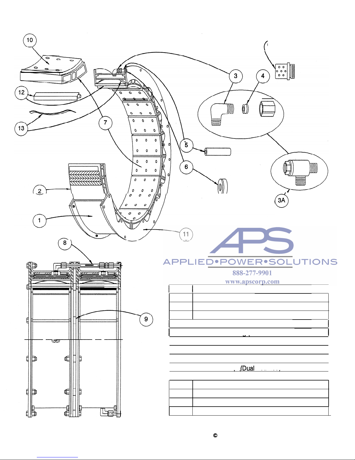
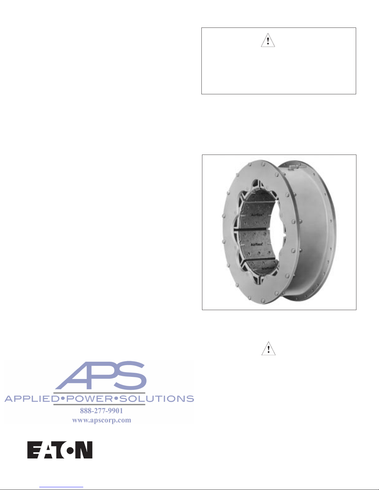
FIG. I- COMPONENT PARTS FOR
AIRFLEX TYPE VC ELEMENT
Optional
Muffler for
(
Quick
Release Valve
0
3A
8
c\
i
ITEM
t
DESCRIPTION
I
1 Rim
2
Tube (w/valve stem snap rings where req’d.)
3
Elbow Assembly
1
3A
Optional - Quick Release Valve Assembly
I
4
Compression Ring (included-with items 3 & 3A)
1
I
5
Air Connection Tube
I
I
6
Air Connection Gasket
I
I
7
Friction Shoe Assembly
I
I
8
I
Air Tube Group
fDual
Mounted)
I
I
9
I
Spacer Group (Dual Mounted)
I
~~ ~-
1O
Replacement Friction Lining & Fasteners
11
Side Plate (2 required)
12
Torque Bar
13
Release Spring
DUAL MOUNTED
1
0
Copyright Eaton Corp., 1989. All rights reserved.
VC 5000
Revised: July, 1995 (PDF format)
1.0 INTRODUCTION
Throughout this manual there are a number of
HAZARD WARNINGS
that must be read and
adhered to in order to prevent possible personal injury and/or damage to equipment.
Three signal words
"DANGER", "WARNING",
and
"CAUTION"
are used to indicate the
severity of a hazard,
and are preceded by the
safety alert symbol
!
A
.
DANGER
- Denotes the most serious
hazard, and is used when serious injury or
death
WILL
result from misuse or failure to
follow specific instructions.
n
!
WARNING
- Used when serious injury
or death
MAY
result from misuse or failure to
follow specific instructions.
n
!
CAUTION
- Used when injury or
product/equipment damage may result from
misuse or failure to follow specific instructions.
It is the responsibility and duty of all personnel
involved in the installation, operation and main-
tenance of the equipment on which this device
is used to fully understand the
P
6
A
I
DANGER,
!
WARNING,
and
!
CAUTION
proce-
dures by which hazards are to be avoided.
11
.
Description
1.1.1
The
Airflex@
air-actuated VC element assembly
is specifically designed and manufactured for
severe clutch or brake applications on heavy
equipment where high starting loads or sustained slippage would normally lower clutch or
brake efficiency and reduce operating life.
Constricting action and ventilated construction
make high torque capacity and rapid heat
dissipation possible.
1.1.2
All Airflex VC element assemblies are supplied
with long wearing, NON-ASBESTOS friction
material.
1
.1
.3
Airflex element assemblies are available
for drum diameters from 11.5 inches through
66 inches. The element size designation indicates the nominal drum diameter in inches, the
clutch model and the width of the friction
material. For example, size “38VC1200"
indicates the element operates on a drum
having a nominal diameter of 38 inches, is an
Airflex “VC” series clutch or brake (the scope’
of this manual) and has friction material which
is 12 inches wide.
VC 5000
Revised: July, 1995 (PDF format)
1.1.4
Where diametral space is limited, or the torque
required is greater than a single element can
transmit, all sizes of Airflex VC elements can
be supplied as dual units.
12
.
1.2.1
How It Works
Referring to Figures 1 and
2,
the neoprene and
cord actuating tube is contained within a steel
rim which is drilled for mounting to the driving
component (or reaction bracket in the case of
a VC brake application). As air pressure is applied to the air actuating tube, the tube inflates,
forcing the friction shoe assemblies uniformly
against the drum which is attached to the
driven component. The friction shoe assemblies, which consist of friction blocks attached to aluminum backing plates, are
guided by torque bars which are secured to
side plates. In the case where the VC element
is being used as a clutch and is attached to
the driving shaft, the torque flow is from the
driving shaft, through the element mounting
component (typically an iron spider), through
the rim/side plate structure, through the torque
bars to the backing plates and friction material,
where the torque is transmitted through the
friction couple to the components mounted
on the driven shaft (clutch drum and drum
mounting component). As actuating air is
exhausted, release springs and centrifugal
force assure positive disengagement.
1.3
1.3.1
Element Adjustment
Airflex VC elements are completely self adjusting and automatically compensate for lining
and drum wear. Lubrication is not required.
The torque developed is dependent upon
rotating speed and applied air pressure. By
limiting the applied pressure, the element will
act as a torque limiting device and provide
overload protection.
1.3.2
To accomplish regulated or cushioned engagement of the element, a flow control valve may
be installed in the element air supply line and
adjusted to restrict air flow to the element
while allowing free flow away from the element
for rapid disengagement. By adjusting the
restricted flow, the rate of engagement may
be varied. Note that the flow control valve
does not regulate air pressure - the supply
pressure must always be adequate to transmit
the maximum required torque. Refer to the
OPERATION section of this manual for air
piping configurations.
2
0
Copyright Eaton Corp., 1989. All rights reserved.
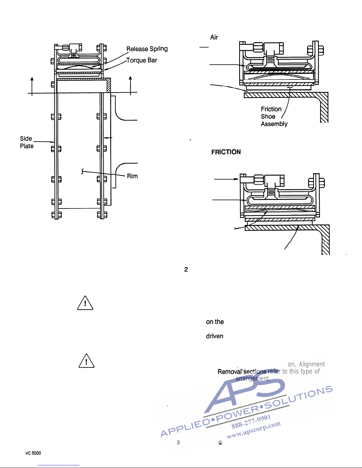
FRICTION SHOE ASSEMBLY
WITHDRAWN
.
Arr
Pressure
Source
2.0 INSTALLATION
2.1
Mounting Arrangements
ing
- Side Plate
F
Rim
n
! Warning:
Only qualified personnel should
install, adjust or repair these units.
Faulty workmanship will result in
exposure to hazardous conditions
or personal injury.
n
! Caution:
Do not inflate the element without
having a drum in place. Inflation of
the element without a drum in place
will result in permanent damage to
the element components.
Y
vc 5000
Tube
Drum
Surface
ICTION MATERIAL CONTACT
Actuating
Z
Air Pressure
Tube
(Inflated)
Release Spring
(Compressed)
r,
Fig.
2
WITH DRUM
Contact
/
With Drum
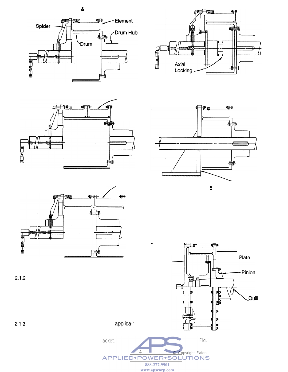
2.1.1
Figure 3 illustrates the gap-mounting arrange-
.
ment. In this arrangement, the element is attached to a spider which is typically mounted
onthe
driving shaft. The drum is attached to a
drum hub which is typically mounted on the
driven shaft. The gap between the two shafts
allows the element and drum to be removed
without disturbing either shaft.
--Note: The text in the Installation, Alignment
and
Removal’Sections
refer to this type of
mounting arrangement.
3
0
Copyright Eaton Corp., 1989. All rights reserved.
. _
Revised: July, 1995 (PDF format)
SINGLE NARROW & SINGLE WIDE
Device
I
J
Fig. 4
DUAL NARROW
Outboard
Element
n-
5\
Brake Reaction
DUAL
WIDE
Outboard Bracket
Fig.
5
/
Element
2.1.4
Figure 6 illustrates a typical marine main
propulsion application. In this arrangement,
the element is attached to a pinion adapter
plate and the drum and drum hub are attached
to a quill shaft. A manifold is attached to the
outboard end of the element for bearing
support of the quill shaft.
*
Pinion
1111
I-
Adapter
t
J
I
Manifold
Fig. 3
2.1.2
Figure 4 illustrates the gap-mounting arrangement with an axial locking device. The axial
locking device restricts the relative axial
motion between the driving and driven shafts.
This arrangement is typically used where a
synchronous motor armature with plain bear-
ings must be held on magnetic center.
\Quill
Shaft
2.1.3
Figure 5 illustrates a typical VC brake
applicao9
tion. The drum and drum hub are attached to
the shaft which is to be stopped. The element
is attached to a rigid reaction bracket.
Fig. 6
4
0
Copyright Eaton Corp., 1989. All rights reserved.
VC 5000
Revised: July, 1995 (PDF format)
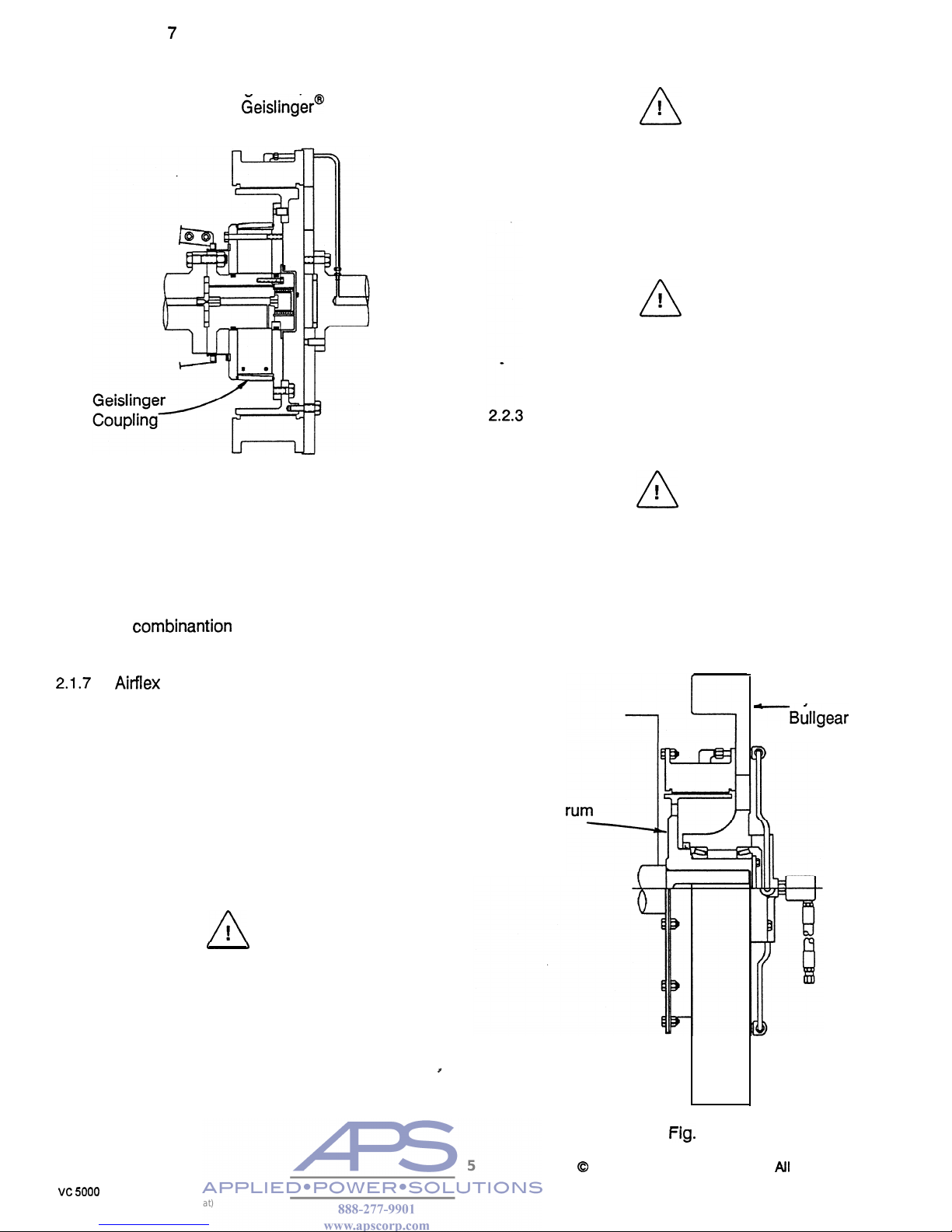
2.15
Figure 7 illustrates a typical marine main
propulsion application where the clutch is
mounted between the engine and reduction
gear. In this arrangement, the VC clutch is
combined with a Geislinger* flexible torsional
coupling.
Fig.
7
2.1.6
Figure 8 illustrates a VC clutch mounting for
punch press applications. The drum and
drum hub are attached to the crankshaft or
backshaft and the element is attached to a
bearing-supported flywheel or bullgear. VC
clutches on punch presses are typically used
in combinantion with Air-flex type CTE and DBA
brakes.
2.1.7
Airflex can provide specific drawings covering
the different mounting arrangements mentioned. The maintenance of the element as-
sembly, tolerances and wear limits of friction
material, and alignment specifications in this
manual apply to all VC applications.
22
.
Mounting Considerations
2.2.1
For clutch and brake applications, shaft align-
ment must be within the tolerances indicated
in the Alignment section of this manual.
A
! Caution:
2.2.2
The element must be protected from con-
tamination from oil, grease or excessive
amounts of dust.
n
! Caution:
Oil or grease contamination will
result in a reduction of developed
clutch or brake torque. Excessive
dust contamination may result in
incomplete disengagement. Either of
these conditions will result in clutch
or brake slippage and overheating.
n
! Caution:
All rotating equipment must be
guarded to comply with applicable
safety standards.
All mounting fasteners must be of the proper
size and grade, and torqued to the appropriate
value. See Table
1.
n
! Warning:
Use only the proper grade and
number of mounting fasteners. Using
commercial grade fasteners (Grade
2)
in place of Grade 8 fasteners (where
called for) may result in failure under
load, causing personal injury or equipment damage.
-Clutch D
and Hub
Operation with shaft misalignment
exceeding the limits indicated in the
Alignment section of this manual will
result in accelerated wear of the element components. Severe misalignment will result in excessive vibration
g
and/or overheating when disengaged
due to dragging of the friction shoes.
t-lg.
8
Flywheel or
-Bullgear
5
0
Copyright Eaton Corp., 1989.
All
rights reserved.
vc 5000
Revised: July, 1995 (PDF format)

TABLE1-FASTENERASSEMBLYTORQUE
SN=SINGLENARROW
SW=SINGLEWIDE
DN=DUALNARROW
DW=DUALWIDE
L=LUBEDTORQUE-FT.-LB.(Nm)(30WT.MOTOROILORANTI-SEIZE)
D=DRYTORQUE-FT.-LB.(Nm)
SIZE
ELEMENTTOSPIDER/
SIDEPLATETORIM TORQUE DRUMTOHUB TORQUE
SN11.5VC500 3/8-16NCGR2 D15(20) 1/2-13NCGR2 D38(51)
SN14VC500 1/2-13NCGR2 D38(51) 1/2-13NCGR2 D38(51)
SN16VC600 1/2-13NCGR2 D38(51) 3/4-10NCGR2 L93(126)
SN20VC600 1/2-13NCGR2 D38(51) 3/4-10NCGR2 L93(126)
SN24VC650 5/8-11NCGR2 D77(104) 3/4-10NCGR2 L93(126)
SN28VC650 5/8-11NCGR2 D77(104) 3/4-10NCGR2 L93(126)
SN33VC650 3/4-10NCGR2 L93(126) 3/4-10NCGR2 L93(126)
SN37VC650 3/4-10NCGR2 L93(126) 3/4-10NCGR2 L93(126)
SN42VC650 3/4-10NCGR2 L93(126) 3/4-10NCGR2 L93(126)
DN11.5VC500 3/8-16NCGR2 D15(20) 1/2-13NCGR8 D109(148)
DN14VC500 1/2-13NCGR8 D87(118) 1/2-13NCGR2 D38(51)
DN16VC600 1/2-13NCGR2 D38(51) 3/4-10NCGR8 L245(332)
DN20VC600 1/2-13NCGR8 D87(118) 3/4-10NCGR8 L211(286)
DN24VC650 5/8-11NCGR2 D77(104) 3/4-10NCGR2 L93(126)
DN28VC650 5/8-11NCGR2 D77(104) 3/4-10NCGR2 L93(126)
DN33VC650 3/4-10NCGR2 L93(126) 3/4-10NCGR2 L93(126)
DN37VC650 3/4-10NCGR2 L93(126) 3/4-10NCGR2 L93(126)
DN42VC650 3/4-10NCGR2 L93(126) 3/4-10NCGR2 L93(126)
SW14VC1000 1/2-13NCGR2 D38(51) 1/2-13NCGR8 L109(148)
SW16VC1000 1/2-13NCGR2 D38(51) 3/4-10NCGR2 L93(126)
SW20VC1000 1/2-13NCGR2 D38(51) 3/4-10NCGR2 L93(126)
SW24VC1000 5/8-11NCGR2 D77(104) 3/4-10NCGR2 L93(126)
SW28VC1000 5/8-11NCGR2 D77(104) 3/4-10NCGR2 L93(126)
SW32VC1000 5/8-11NCGR2 D77(104) 3/4-10NCGR2 L93(126)
SW38VC1200 3/4-10NCGR2 L93(126) 3/4-10NCGR2 L93(126)
SW42VC1200 3/4-10NCGR2 L93(126) 3/4-10NCGR2 L93(126)
SW46VC1200 7/8-9NCGR2 L109(148) 1-8NCGR2 L163(221)
SW52VC1200 7/8-9NCGR2 L109(148) 1-8NCGR2 L163(221)
SW51VC1600 7/8-9NCGR2 L109(148) 1-8NCGR2 L163(221)
SW60VC1600 1-8NCGR2 L163(221) 11/2-6NCGR2 L566(767)
SW66VC1600 11/4-7NCGR2 L325(441) 11/2-6NCGR2 L566(767)
DW16VC1000 1/2-13NCGR8 D87(118) 3/4-10NCGR8 L245(332)
DW20VC1000 1/2-13NCGR8 D87(118) 3/4-10NCGR8 L245(332)
DW24VC1000 5/8-11NCGR8 D174(236) 3/4-10NCGR8 L245(332)
DW28VC1000 5/8-11NCGR8 D174(236) 3/4-10NCGR8 L245(332)
DW32VC1000 5/8-11NCGR8 D174(236) 3/4-10NCGR8 L245(332)
DW38VC1200 3/4-10NCGR8 L245(332) 3/4-10NCGR8 L245(332)
DW42VC1200 3/4-10NCGR8 L245(332) 3/4-10NCGR8 L245(332)
DW46VC1200 7/8-9NCGR2 L109(148) 1-8NCGR8 L510(692)
DW52VC1200 7/8-9NCGR2 L109(148) 1-8NCGR8 L510(692)
DW51VC1600 7/8-9NCGR2 L109(148) 1-8NCGR8 L510(692)
DW60VC1600 1-8NCGR2 L163(221) 11/2-6NCGR2 L566(767)
DW66VC1600 11/4-7NCGR2 L325(441) 11/2-6NCGR2 L566(767)
HEXSIZES(in.)
SIZE BOLT NUT SIZE BOLT NUT SIZE BOLT NUT
3/8NC 9/16 9/16 3/4NC 1-1/8 1-1/16 1-1/4NC 1-7/8 1-13/16
1/2NC 3/4 3/4 7/8NC 1-5/16 1-1/4 1-1/2NC 2-1/4 2-3/16
5/8NC 15/16 15/16 1NC 1-1/2 1-7/16
VC5000 Revised:July,1995(PDFFormat)
6
23
.
Mounting Spider and Drum Hub
2.3.1
The spider and drum hub are bored for a
press fit onto their respective shafts. The inter-
ference is approximately .0005 in. per inch
(.0005mm/mm) of shaft diameter.
2.3.1 .1
Ensure the shaft is clean and free of nicks or
burrs and check the shaft and bore diameters
for proper fit.
2.3.1.2
Tap the key into the keyway, making sure it
bottoms.
2.3.1.3
Apply a light coat of anti-seizing compound to
the shaft and key.
2.3.1.4
Heat the drum hub or spider uniformly to
25O*F
(121*C)
to expand the bore.
1
n
! Caution:
It is recommended the drum hub
or spider be heated in oil or an oven;
however, since this is not always
possible, torches may be used. When
using torches, use several with
“rosebud” (broad-flame) tips and keep
them moving to avoid “hot spots”.
Check bore temperature frequently to
avoid overheating.
2.3.1.5
Slide the heated drum hub or spider onto the
shaft until the hub face is flush with the end of
the shaft. Hold in position and allow to cool.
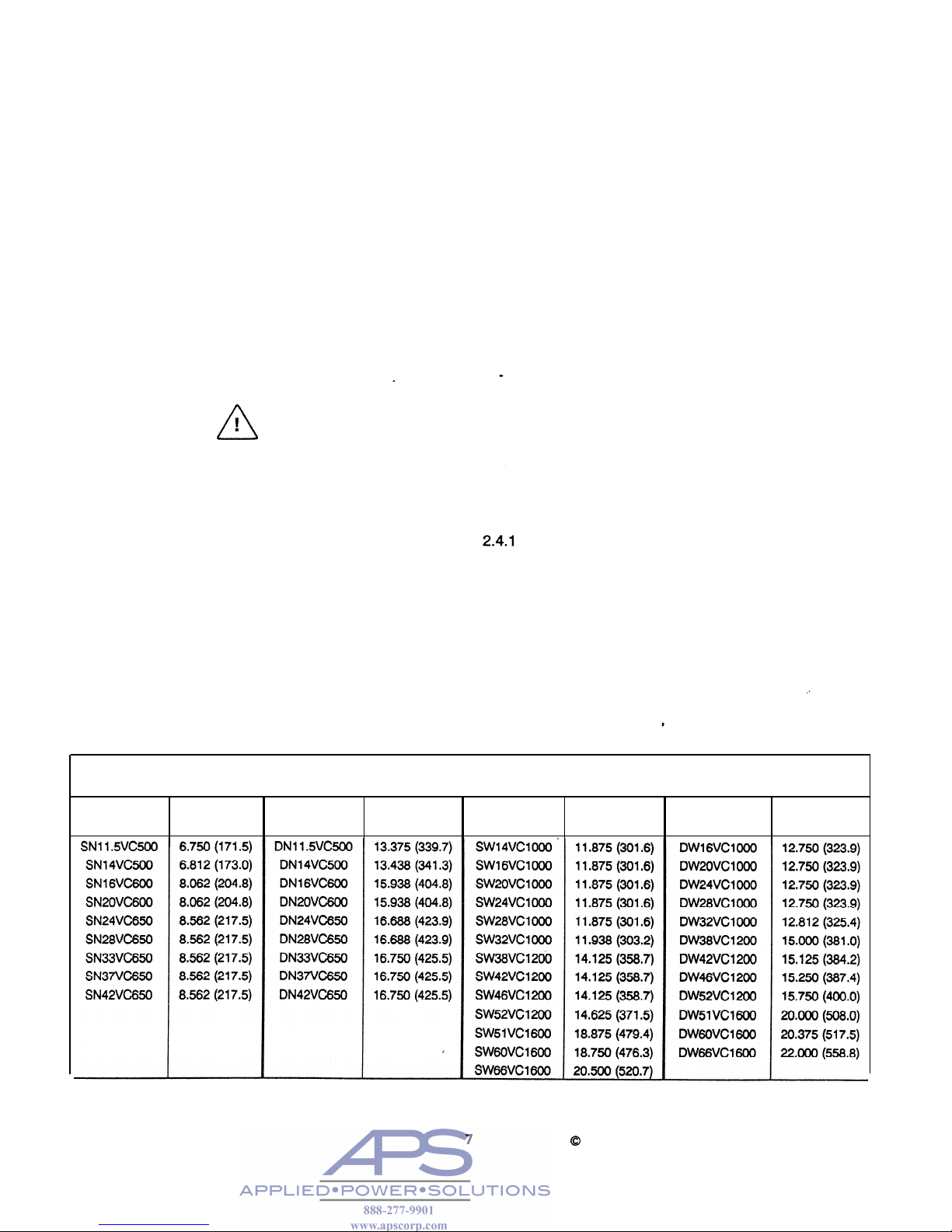
24
.
Shaft Alignment
Note: The text in this section applies to gapmounted applications; however, the alignment
tolerances apply to all types of mountings.
Parallel Alignment Tolerance
(Off set):
Not to exceed 0.010 inch (.254mm) Total
Indicator Reading (0.005 in. (.127mm)
maximum offset).
Angular Alignment Tolerance (Gap):
Not to exceed 0.0005 inch per inch
(.0005mm/mm) diameter at which readings
are taken ("D” on Fig. 9).
Note: The alignment procedure described
below has been used successfully on many
VC clutch and brake applications. Other
procedures, of course, may be used; however,
the alignment tolerances are the same regardless of the technique used.
Foundations must be set so distance "X”,
shown on Figure 9, is established. If the clutch
is mounted on a shaft having plain bearings,
make sure the shaft is centered within the bearings when establishing the “x” dimension.
Refer to Table 2 for appropriate "X" dimensions.
Note: It is presumed that one of the shafts has
been properly located and anchored.
_*
TABLE 2 - “X” DIMENSIONS (FIG. 9)
SIZE
“X" in.
SIZE
"X" in.
SIZE
"X" in.
SIZE
"X” in.
(mm)
(mm)
(mm)
(mm)
7
0
Copyright Eaton Corp., 1989. All rights reserved.
VC 5000
Revised: July, 1995 (PDF format)
 Loading...