

Eaton AirFlex TLC 5004 Installation, Operation And Maintenance Manual
TLC 5004 - Installation, Operation and Maintenance Manual
®
Airex
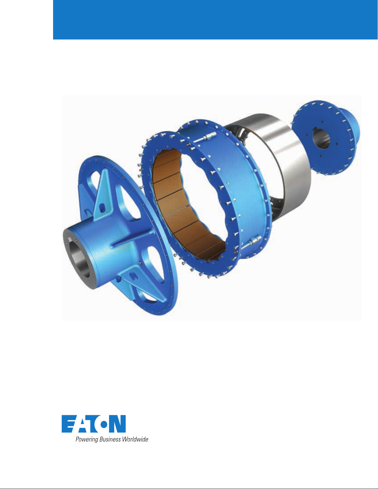
Torque Limiting Coupling

Torque Limiting Coupling
General information
Warning
Forward this manual to the person responsible for Installation,
Operation and Maintenance of the product described herein.
Without access to this information, faulty Installation,
Operation or Maintenance may result in personal injury or
equipment damage.
Caution
Use Only Genuine Airex Replacement Parts.
The Airex Division of Eaton Corporation recommends
the use of genuine Airex replacement parts. The use of
non-genuine Airex replacement parts could result in
substandard product performance, and may void your
Eaton warranty.
For optimum performance, contact Airex:
In the U.S.A. and Canada: (800) 233-5890
Outside the U.S.A. and Canada: (216) 281-2211
EATON Torque Limiting Coupling Installation, Operation and Maintenance Manual E-MEQD-II002-E September 20152

Table of contents
Section Description Page no
1.0 Introduction 6
1.1 Description 6
1.2 How it works 6
1.3 TLC adjustment 7
2.0 Installation 7
2.1 Mounting arrangements 7
2.2 Mounting considerations 7
2.3 Mounting spider and drum hub 8
2.4 Shaft alignment 9
2.5 Axial locking device adjustment 10
2.6 Installation of single wide element and drum 11
2.7 Air control system 11
2.8 Electrical controls 11
3.0 Operation 12
3.1 Torque, RPM and Pressure Limits 12
3.2 Control component adjustment 12
4.0 Maintenance 12
4.1 Periodic inspection 12
4.2 Removal of element assembly and drum 14
4.3 Removal of spider and drum hub 14
4.4 Disassembly of the element 14
4.5 Friction shoe assembly replacement 14
4.6 Assembly of the element 15
5.0 Spare parts storage 15
5.1 Element assemblies 15
5.2 Drums 15
5.3 Air actuating tubes 15
6.0 Ordering information/technical assistance 15
6.1 Equipment reference 15
7.1 Parts breakdown of TLC element assemblies gures 1 and 10 16
8.1 Parts breakdown of TLC hub, spider, drum, axial locking assy. and rotorseal gure 2 16
9.1 (Standard) Torque bar kit 17
9.2 (Standard) Friction shoe assembly, torque bar and release spring kit 17
10.1 Description axial locking assembly 17
EATON Torque Limiting Coupling Installation, Operation and Maintenance Manual E-MEQD-II002-E September 2015 3
Torque Limiting Coupling
4
5
See Figure 10
3
9
10
7
2
1
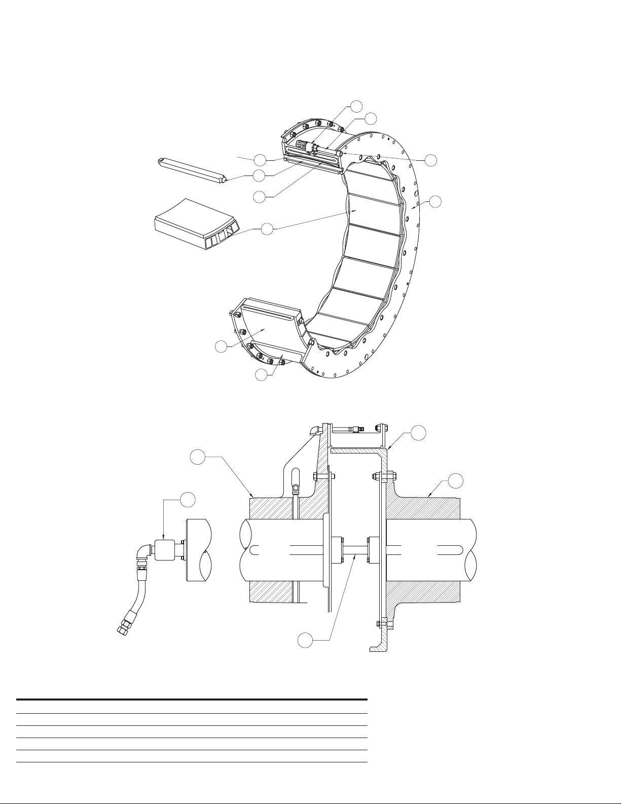
Figure 1
6
8
13
Item Description
1 Rim
2 Tube
3 Snap rings
4 QRV
5 Air tube
12
15
Item Description
6 Rubber washer
7 Friction shoe assembly
8 Side plate (2 required)
9 Torque bar
10 Release spring
11
14
Figure 2
Item Description
11 Hub
12 Spider
13 Drum
14 Axial locking assembly
15 Rotorseal
EATON Torque Limiting Coupling Installation, Operation and Maintenance Manual E-MEQD-II002-E September 20154
Torque Limiting Coupling
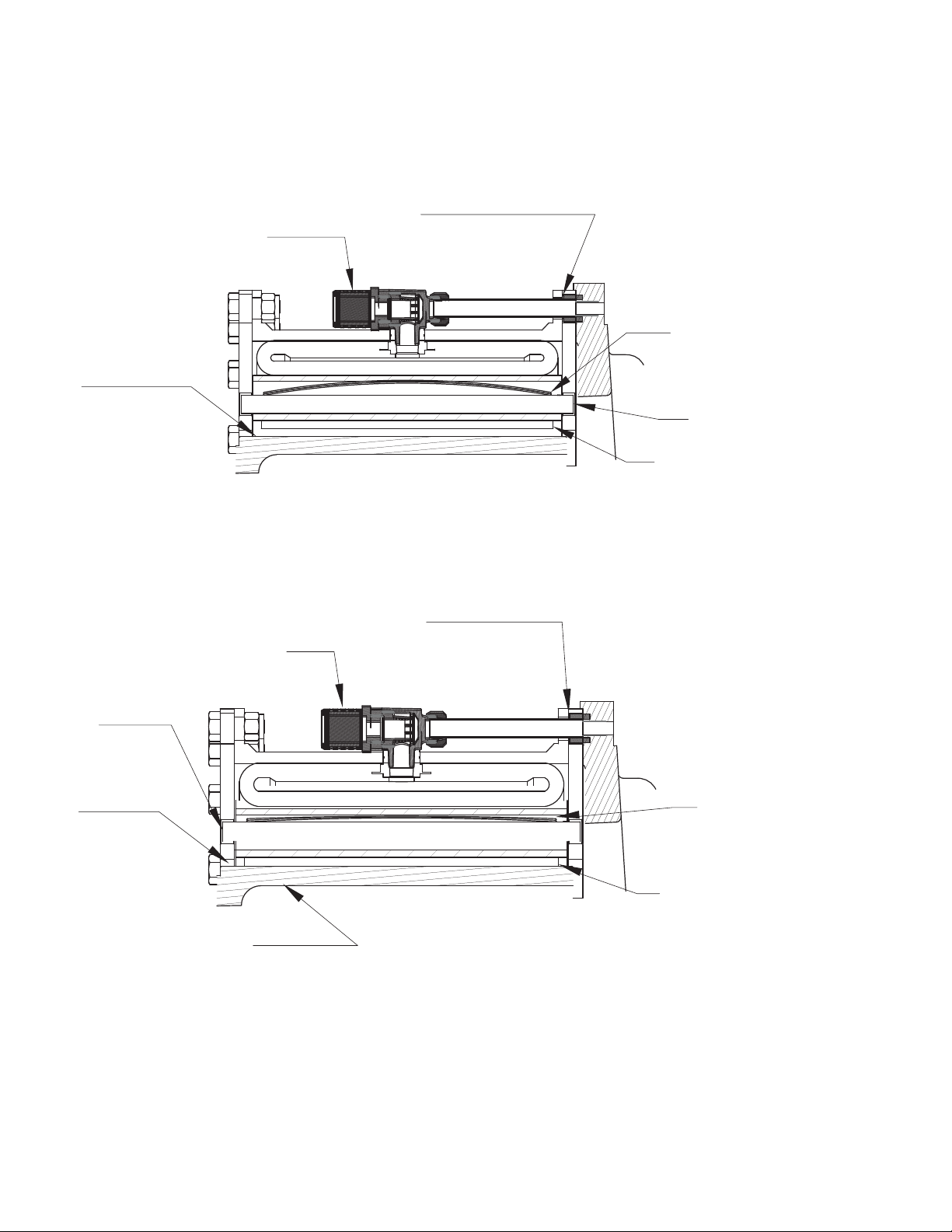
Friction Material in contact with the drum
Drum surface
Friction shoe assembly retracted
QRV
Drum surface
Rubber backed washer
Release spring
Torque bar
Friction shoe assembly
Figure 3
QRV
Torque bar
Drum surface
Rubber backed washer
Release spring
(Compressed)
Contact with drum
Figure 4
EATON Torque Limiting Coupling Installation, Operation and Maintenance Manual E-MEQD-II002-E September 2015 5

Torque Limiting Coupling
1.0 Introduction
Throughout this manual there are a number of
HAZARD Warnings that must be read and adhered
to in order to prevent possible personal injury and/
or damage to equipment. Three signal words
Danger, Warning and Caution are used
to indicate the severity of a hazard, and are preceded
by the safety alert symbol
Danger
Denotes the most serious hazard, and is used
when serious injury or death WILL result from
misuse or failure to follow specic instructions.
Warning
Used when serious injury or death MAY
result from misuse or failure to follow
specic instructions.
Caution
Used when injury or product/ equipment
damage may result from misuse or failure to
follow specic instructions.
It is the responsibility and duty of all personnel
involved in the installation, operation, and
maintenance of the equipment on which this device
is used to fully understand the Danger, the
Warning and the Caution procedures by which
hazards are to be avoided.
1.1 Description
1.1.1 The Airex Torque Limiting Coupling (TLC) is air
actuated and specically designed and manufactured
for service in grinding mill and other torque limiting
applications. Torque limiting is required by variable
speed grinding mills directly coupled by the TLC
to the mill drive train to prevent damage to the entire
drive system from unintended torque spikes or
overloading conditions. The TLC provides a means to
immediately disengage the mill from the motor(s)
when the torque required to drive the mill is
excessive and detected by the TLC system. The
constricting design and construction make the TLC
high torque capacity possible.
In these applications, the TLC will be engaged by
applying the specied air pressure when the
drive system is at rest. The mill is started from this
static condition by the drive(s) and over time
brought up to the nominal operational speed. For
overload conditions above the rated set point of
the TLC it begins to slip resulting in a differential
of speeds between the driving and driven shafts.
At a predetermined level of slippage based on
rpm, the TLC controls disengage the TLC element(s)
instantaneously by releasing the applied air pressure.
1.1.2 All Airex TLC elements are supplied with long
wearing, NON-ASBESTOS high coefcient friction
material. The material is capable of withstanding
the energy input that is developed during the short
overload condition when slippage occurs
between the driving and driven shaft before the
automatic disengagement of the element(s) by the
control system.
1.1.3 Airex TLC element assemblies are now available in
sizes from a 51TLC1600 through a 76TLC2000.
The element size designation indicates the nominal
drum diameter in inches, the TLC model and the
width of the high coefcient friction material. For
example, size “51TLC1600” indicates the element
operates on a drum having a nominal diameter of
51 inches and has friction material which is 16 inches
in width.
1.2 How it works
1.2.1 Referring to Figures 1, 2, 3 and 4, the neoprene and
cord actuating tube is contained within a steel rim
which is drilled for mounting to the driving
component. As air pressure is applied to the air
actuating tube, the tube inates, forcing the
friction shoe assemblies uniformly against the
drum, which is attached to the driven component.
The friction shoe assemblies, which consist of the
special high coefcient friction pads bonded to
aluminum backing plates, are guided by torque bars
which are inserted into the element side plates.
The torque path is from the driving shaft, through
the element mounting component (typically an iron
spider), through the element rim and side plates and
the torque bars, backing plates and friction material.
The torque is then transmitted through the friction
couple to the driven shaft. When the specied
applied air pressure is exhausted, release springs
and centrifugal force assure immediate and
positive disengagement.
1.2.1.1 In some cases, the spider and element assembly
may be mounted to the driven shaft rather than
the driving shaft. This “reverse-mounted”
arrangement is typically used when retrotting a mill
drive and it is more practical to drill the pinion shaft
for the air supply rather than the motor shaft. In
these cases, the operation and torque ow
description is opposite to what is stated above.
1.2.1.2 For TLC applications that are mounted to the
drive motor(s) an axial locking device is used to hold
the motor on magnetic center during operation.
Refer to the INSTALLATION section for axial locking
device adjustment.
EATON Torque Limiting Coupling Installation, Operation and Maintenance Manual E-MEQD-II002-E September 20156
 Loading...