

Eaton Aeroquip Rynglok Fitting System Installation Manual
Aeroquip
Rynglok
®
®
Fittings
Rynglok
Fitting System
Installation Guide

Rynglok Fitting System Installation Guide
1.0 Initial Preparation .................................................................................... 3
1.1 Cutting Tubes
1.2 Tube End Preparation
1.2.1 Painted Tube End Preparation
1.3 Pre-applied Tube End Marking
1.4 Marking Gauge Positioning
2.0 Fitting Installation ................................................................................... 4
2.1 Positioning Mark
2.1.1 End Fittings
3.0 Fitting Assembly ..................................................................................... 5
3.1 Assembly Tool Selection
3.1.1 Assembly Tool/Fitting Compatibility
3.2 Assembly Tool Pressure Connection
3.3 Tool Installation
3.4 Tool Pressure
3.4.1 Pressure Level
4.0 Assembled Fitting Inspection ................................................................. 6
4.1 Ring Advancement Inspection
4.1.1 Insertion Inspection Mark Position
4.2 Shared Insertion - Unions
4.2.1 Over Insertion Condition - Fittings Other Than Unions
5.0 Tubing Repair With Rynglok Unions ........................................................ 7
5.1 Single Union Repair
5.1.1 Cutting Through Center Of Defect
5.1.2 Cutting Out Defect
5.2 Two Union Repair
6.0 Special Considerations ........................................................................... 8
6.1 Using The “Reversed Tool”
6.2 Special Considerations When Using The “Reversed Tool”
6.3 Special Considerations When Using The -20 and -24 Tools
7.0 Tube Cut Dimensions ............................................................................. 9
7.1 Female Arcseal™ Fitting
7.2 Female Flareless Fitting
7.3 Female Flared Fitting
8.0 Fitting Selection Chart ........................................................................10 – 11
2 EATON Aerospace Group TF100-67A March 2013

Rynglok Fitting System Installation Guide
1.0 Initial Preparation
1.1 Cutting Tubes
Tubes may be cut using any appropriate cutting tool whether by
hand or by a production method. Tube ends should be reasonably
square, recognizing that any out-of-squareness condition will detract
from the amount of positioning tolerance allowed. (See paragraph
1.4)
1.2 Tube End Preparation
The tube ends should be deburred with appropriate deburring tools
on the O.D. and I.D. to prevent damage of the fitting I.D. during tube
insertion and to prevent FOD (Foreign Object Damage) from entering
and contaminating the fluid system.
1.2.1 Painted Tube End Preparation
Painted tube ends shall be deburred in accordance with paragraph
1.2. Painted tube ends do not require the paint to be removed when
the tubing O.D. is in accordance with Table 1. The max. tubing O.D.
(dim. A) must be held a min. distance (dim. B) per Table 1 for proper
fitting installation. If paint removal is necessary, the tube shall be
sanded in a radial direction using a mild grit paper. Care should be
taken to prevent longitudinal marks. It will be necessary to reclean
and remark tube ends. It is recommended to repaint the exposed
tubing after installation. Please contact Eaton’s Jackson, MI facility at
(517) 787-8121 if there are any questions regarding this procedure.
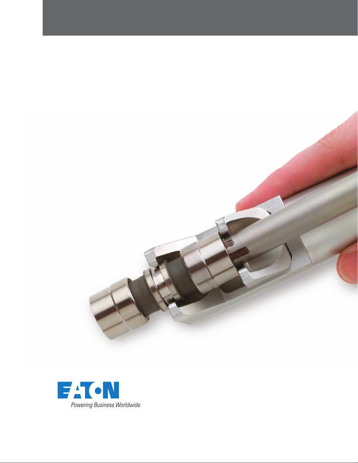
1.3 Pre-applied Tube End Marking
A pair or pairs of marks, (positioning marks and inspection marks) as
shown in Figure 1, should be pre-applied with the given dimensions
from Table 1 to each prepared tube end prior to fitting installation.
A suitable method such as ink stamp, electro-etch, laser, etc. may
be used. Should the tube ends be unmarked, the appropriate marks
should be applied using Eaton’s Aeroquip brand tube marking gauge
P/N RTSG0-01-SIZE as shown in Figure 2, and using a suitable permanent ink felt tipped pen.
Notice: Due to the possibility of contaminating titanium tubing, inks
which contain lead or free halogens should not be used for marking.
Table 1
Dimensions for electro-etch, ink stamp, or laser marking.
Dash
Size
-03 .190 .453 .300 .453 .644
-04 .254 .525 .300 .525 .717
-05 .316 .588 .300 .588 .780
-06 .379 .656 .300 .656 .843
-07 .441 .730 .300 .730 .918
-08 .505 .773 .350 .773 .963
-09 .567 .836 .350 .836 1.026
-10 .630 .899 .350 .899 1.088
-11 .692 .983 .350 .983 1.175
-12 .755 1.042 .350 1.042 1.232
-13 .817 1.110 .350 1.110 1.303
-14 .880 1.178 .350 1.178 1.369
-15 .942 1.249 .400 1.249 1.448
-16 1.006 1.299 .400 1.299 1.498
-20 1.256 1.572 .400 1.572 1.781
-24 1.507 1.882 .400 1.862 2.086
A
Max.
B
Min.
C
± .005D ± .005E ± .005
Figure 1
Tube marking using electro-etch, ink stamp, or laser marking.
1.4 Marking Gauge Positioning
The RTSG0-01-SIZE series of marking gauges is common for all
pressure classes of Rynglok fittings. The marking gauge should be
bottomed on the end of the cut tube. If an out-of-square condition
exists, the marking gauge should be positioned toward the end that
is most square. This is only for fittings which require shared insertion, such as in the case of a union fitting. This allows minimum tube
insertion on the opposite end of a union configuration should the
skew end be inserted to the maximum tube insertion condition. (See
paragraph 4.1.1 and Figure 7).
(All tubes should be marked prior to assembly in insure proper tube
insertions.)
Figure 2
Application of tube insertion marks using RSTG0-01-SIZE marking gauge and
pen.
EATON Aerospace Group TF100-67A March 2013 3
Rynglok Fitting System Installation Guide
2.0 Fitting Installation
2.1 Positioning Mark
The installer must use this positioning mark to position the edge of
the unswaged fitting “ring” over the marks as shown in Figure 3.
The length of the positioning mark is the amount of positioning tolerance allowed. The edge of the fitting “ring” may be anywhere along
the length of the positioning mark.
Figure 3
Fitting position for tube insertion
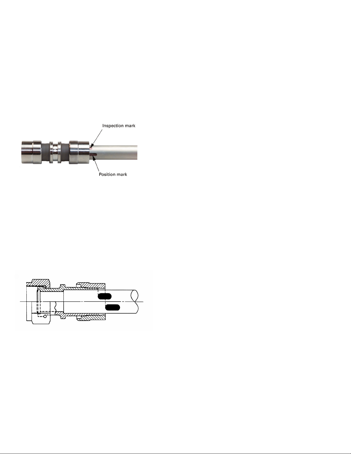
2.1.1 End Fittings
In general, end fittings are designed to have the tube end bottomed
into the fitting, and do not have as much positioning allowance. See
Figure 5. Even with this condition, the tube end should be marked
for inspection purposes to verify that the tube was inserted to at
least the minimum insertion depth. Refer to section 7.0 when installing fittings of this type.
Figure 4
End fitting tube positioning. Note: Tube is bottomed into fitting.
4 EATON Aerospace Group TF100-67A March 2013
 Loading...