


Eaton Aeroquip AE246 Assembly And Disassembly Instructions For Hand And Machine Assembly
Aeroquip
®
AE246 High Pressure
PTFE Hose
and “super gem”™
Reusable Fittings
Assembly and disassembly instructions
for hand and machine assembly

Table of Contents
Section I Introduction 1
1. Purpose 1
2. Scope — “super gem” Fittings 1
3. Description 1
Section II Identification 2-4
1. Identification and Construction of AE246 PTFE Hose 2
2. Fire Sleeve 2
3. Fittings - “super gem” Fittings 3
4. Hose Assemblies 3
Section III Disassembly 5
Section IV Cleaning 6
Section V Repair and Replacement 7
1. General 7
2. Fire Sleeved Hose Lines 7
Section VI Assembly Procedure — Hand Tool Method 8-11
Section VII Assembly Procedure — Machine Tool Method 12
1. General 12
2. Assembly of Fitting to Hose 12
Section VIII Proof Test Procedures 13
1. Equipment 13
2. Recommended Hydrostatic and Pneumatic Proof Test Pressures 13
3. Hydraulic Proof Test 13
4. Pneumatic Proof Test 13
5. Disposition If Fitting Leakage Is Noted 13
6. After Proof Test Operation 13
Section IX Removal of Hose Assemblies from Installation 14
1. Inspection 14
2. AN-MS Flared and Flareless Connections 14
3. Handling General 14
Section X Installation of Hose Assemblies 15-16
1. Installation, General 15
2. Routing and Clamping 15
3. Torque Values, Installations 16
4. “super gem” Fittings Used on Aeroquip AE246 Hose 16
Section XI Inspection Procedures 17-18
1. External Inspection of Hose Lines Removed from Service 17
2. Internal Inspection of Hose Lines Removed from Service 17
3. Hose End Fittings 17
4. Inspection of Component Parts 18
Section XII Permissible Rework 19
1. Hose Assemblies 19
2. Hose 19
3. Fittings 19
4. Fire Sleeves 19
Section XIII Storage of Hose and Hose Assemblies 20
1. Age Limitations 20
2. Bulk Hose 20
3. Hose Assemblies 20
Section XIV Disposition 20
Section XV Assembly Equipment, Special Tools, Fixtures and Service 21
1. Purpose
This manual provides specific instructions for
maintenance and overhaul of Eaton’s Aeroquip hose
assemblies made of high-pressure tetrafluoroethylene
(PTFE) hose. Eaton’s Jackson, Michigan facility
manufactures Aeroquip products (Federal Code
Number 00624). The manual is divided into three
areas of maintenance to enable each maintenance
group to complete its service within a sequence
of sections. The first area, following “Introduction”
and “Identification” which are common to all levels,
contains the maintenance and overhaul procedures for
hose assemblies removed from service (Sections III
through VIII). The second area provides maintenance
and replacement instructions for hose assemblies which
are in service (Sections IX through X). The last area of
the manual is devoted specifically to inspection, storage
and disposition of hose assemblies (Sections XI through
XIV).
2. Scope
Hose assemblies fabricated in accordance with this
manual will conform to the requirements listed in
Specification MIL-H-38360 and are suitable for use in
high temperature, 3,000 psi hydraulic and pneumatic
systems. Use in other systems is permissible where
pressure and fluid are compatible with the requirements
of the specifications and as further specified in
paragraph 6.1 of MIL-H-38360 or when specifically
approved by Eaton.
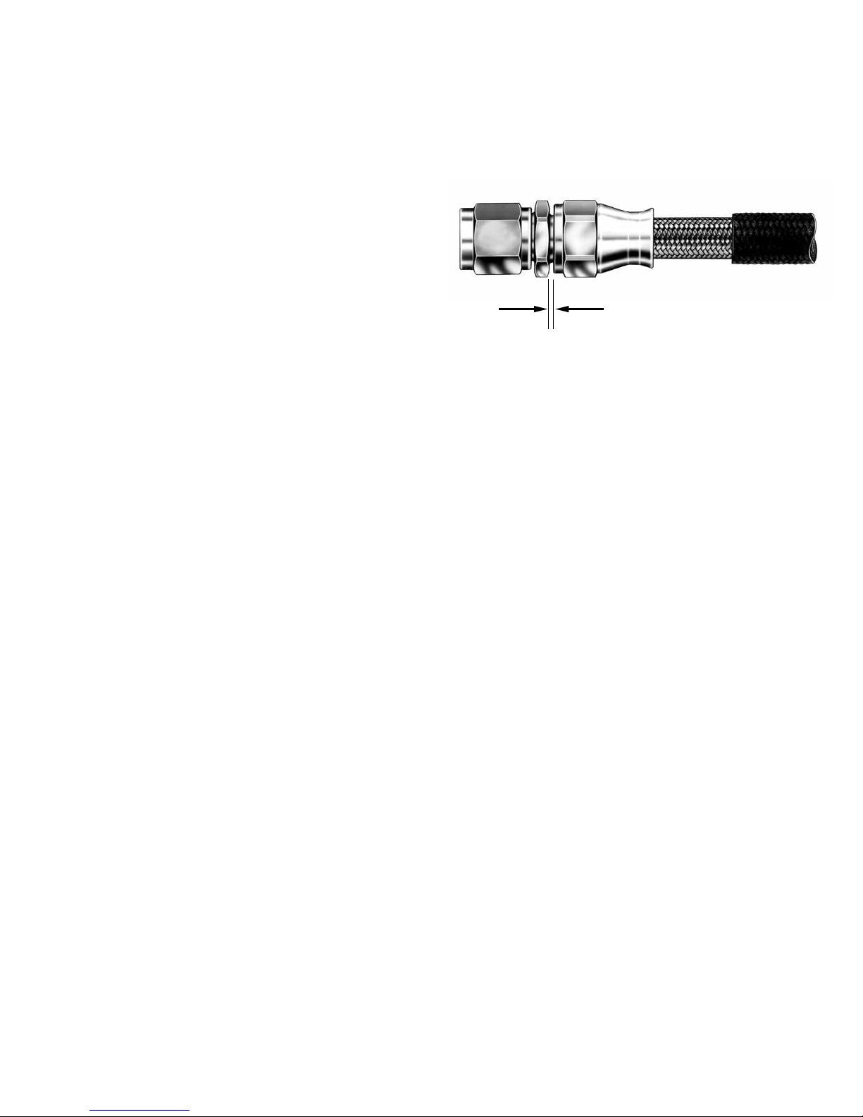
One gap - all sizes
1/32 inch (.793 mm)
Section I
Introduction
+ .015
- .008
3. Description
AE246 High Pressure PTFE Hose and reusable “super
gem” fittings are manufactured by Eaton. Where
applicable, supplementary information covering these
hose lines protected with Eaton’s Aeroquip fire sleeve is
included.
EATON Aerospace Group TF100-63B October 2018 1
Section II
Identification
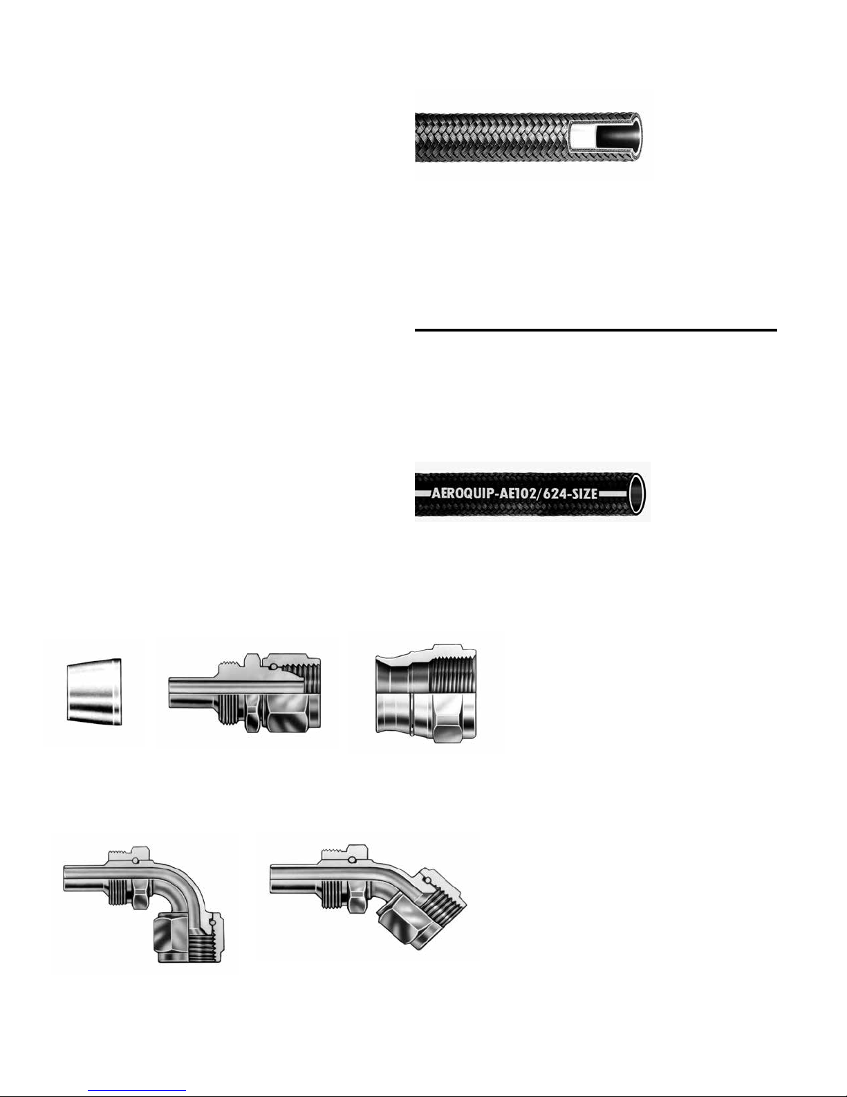
1. Identification and Construction of AE246 High Pressure
PTFE Hose
A. AE246 PTFE hose (Figure 1) conforming to the
requirements of MIL-H-38360 has a corrosion resistant
steel wire braid reinforcement covering an extruded
PTFE inner tube. See Table 1.
B. Identification of AE246 PTFE Hose
1) Bulk hose Identification — Bulk hose has a tape
with black letters specifying Aeroquip hose – size,
operating pressure, lot number and hose manufacturer’s code. Tape is located at each end and in
middle of hose.
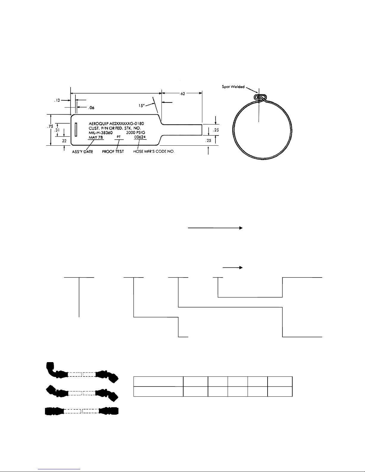
2) Hose Assembly Tag Identification — All factory
assembled hose assemblies are identified with
a metal band. Identification may include such
information as customer part number, Federal Stock
Number if required, hose assembly specification
number, operating pressure in psig, manufacturer’s
assembly part number, proof test symbol, date of
assembly, and hose manufacturer’s Federal Code
Number. See Figure 5.
Figure 1 - AE246 Bulk Hose
Table I
General Specifications — Aeroquip AE246 PTFE Hose
Hose Size Tube Size
O. D.
inches (mm)
- 4 1/4 (6.35) 3000 (206.84) 16000 (1103.16) 1.50 (38.09)
- 6 3/8 (9.52) 3000 (206.84) 14000 (965.26) 2.50 (63.50)
- 8 1/2 (12.70) 3000 (206.84) 14000 (965.26) 2.88 (73.15)
- 10 5/8 (15.87) 3000 (206.84) 12000 (827.37) 3.25 (82.55)
- 12 3/4 (19.05) 3000 (206.84) 12000 (827.37) 3.88 (98.55)
Operating
Pressure
psig (bar)
Min. Burst
Pressure
psig (bar)
Min. Bend
Radius
inches (mm)
2. Fire Sleeve
AE102/624 firesleeve is identified by a red silicone
impregnated, braided asbestos sleeve having a black lay
line with “Aeroquip AE102/624”– size repeated at 10 inch
intervals.
Figure 2 - Fire Sleeve
3. Fittings
All component parts of fittings are impression-stamped
with the part number.
Sleeve Nipple Assembly Socket
Figure 3. “super gem” fitting consists of 3 pieces: socket, sleeve and nipple assembly.
90º Adjustable Elbow 45º Adjustable Elbow
Figure 4. “super gem” elbow fittings
2 EATON Aerospace Group TF100-63B October 2018
4. Hose Assemblies
AE2460500 E 0184
Complete assembly number
(hose assembly with straight fittings
or elbow on one end only)
Complete assembly number
AE4108 E 0184 225
(hose assembly with elbow or
BASIC STYLE NUMBER
HOSE SIZE (letter code)
Hose size is expressed as a letter code which designates
following the basic style.
Hose dash size -4 -6 -8 -10 -12
Letter code E G H J K
All factory assembled hose lines are identified with a metal
band (Figure 5) containing part numbers, date of assembly,
etc. A detailed explanation of the different elements of a
hose assembly part number is shown in Figure 6.
Figure 5. Identifying Metal Band
How To Complete Assembly Part Number
Basic types of hose assembly numbers are shown below.
A detailed explanation of the different elements of the part
numbers are given on these pages.
Section II
Identification
Select hose required and choose correct assembly part
number – basic style number – covering desired
configuration. Use Aeroquip Aerospace Engineering Bulletin
AEB 212 as a reference guide.
Figure 6 - Assembly Part Number Explanation
special fitting on each end)
the tube O.D. in 1/16’s of an inch, for example, ½ - inch = 8 or letter code H. This code is added immediately
EATON Aerospace Group TF100-63B October 2018 3
Section II
Identification
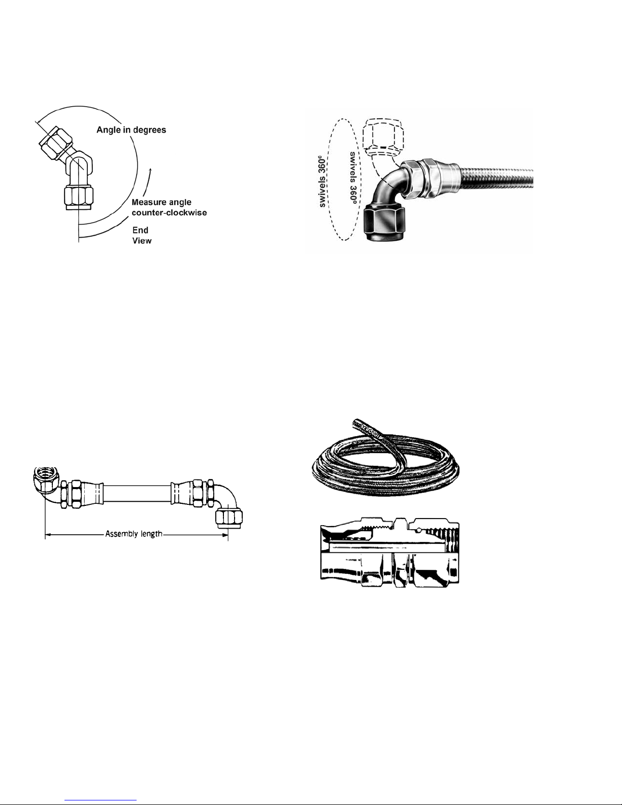
Position Angle (Angle of Rotation)
For assemblies with an elbow fitting on each end, measure the
position angle as shown and suffix the angle to the basic style
number. The angle is expressed in three digits. For example: 35°
would be written as 035. If the angle desired is 0°, specify as
000. The angle shown in the example is 225°.
Assembly Length
Assembly length is measured from sealing surface to sealing
surface. On elbow fittings the measuring point is the intersection of the centerline of the elbow with the face of the sealing
surface. Assembly length will always be expressed in four digits.
Last digit shall always indicate fractional length in 1/8’s of an
inch. Thus, an assembly 18-1/2 long will be indicated as 0184.
Assembly Length Tolerances (PTFE Hose)
18 inches or less ± 1/8 inch
18 inches to 36 inches ± 1/4 inch
36 inches or longer ± 1% length
Adjustable elbow fittings are easily positioned through 360°
to the desired relative angle between opposite elbow fittings.
Mock-up and prototype installation changes are simplified as the
position angle can be determined on the actual installation.
Bulk Hose
300 ft., AE246-8 Hose (random lengths)
300 pcs., AE246-8-0120 (specific lengths)
PTFE hose will be shipped in random lengths. If specific lengths
are required, order as shown in the example above. An additional
charge is made on orders for specific lengths.
Typical Straight Flareless Fitting Assembly
For complete configuration and style information, use Eaton Bulletin AEB 212
as a reference guide.
4 EATON Aerospace Group TF100-63B October 2018
1. Complete Assembly Tear-Down
Procedure for salvage of hose assembly components:
Section III
Disassembly
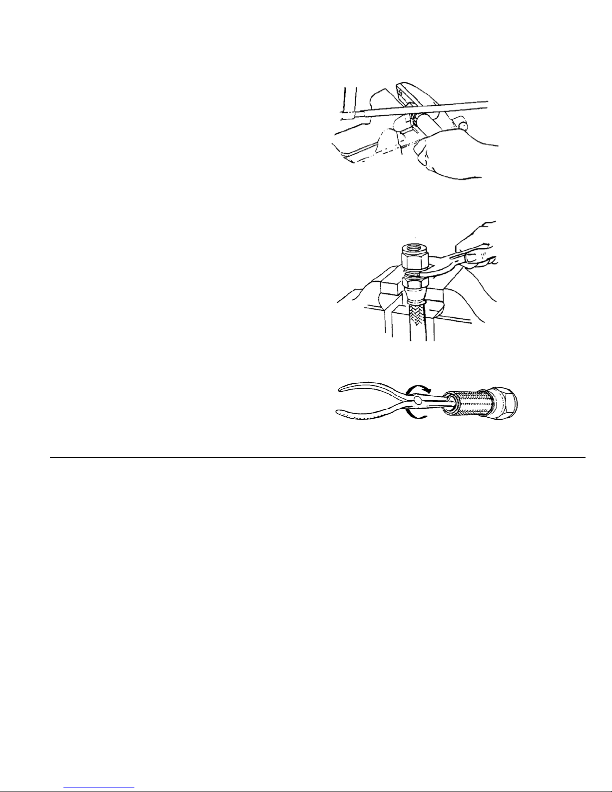
Step 1. (Fire-sleeved hose lines only). Remove band
clamps by cutting clamp “buckles” with hack
saw. Remove fire sleeve from hose assembly.
(See Figure 7.)
Step 2. Place socket in vise and remove nipple
assembly by applying wrench to nipple hex.
(See Figure 8.)
Step 3. Cut hose approximately 1-inch from socket
skirt.
Step 4. Hold socket firmly in vise. Do not damage
socket. Using needle nose pliers, remove the
tube from the sleeve and hose reinforcement.
(See Figure 8A). The tube may be removed by
folding longitudinally and pulling it out of the
socket.
Step 5. With the socket still in the vise, separate the
sleeve from the socket and hose reinforcement.
The reinforcement can then be pulled out of
the socket.
Step 6. Remove hose fitting from opposite end of
assembly, using the same procedures, step 2
through step 5.
Step 7. Disposition of Component Parts — All hose
shall be scrapped and component parts of
fittings shall be inspected in accordance with
inspection procedures. See Section XI.
Figure 7. Removing Fire Sleeve From Hose Assembly
Figure 8. Removing Nipple From Socket
Figure 8A. Removing Tube From Sleeve
EATON Aerospace Group TF100-63B October 2018 5

Section IV
Cleaning
1. General
It is recommended that all hose assemblies and
component parts be thoroughly cleaned and
degreased before inspection.
A.
Cleaning Hose Assemblies with AE102/624 Fire
Sleeve
— It is suggested that the fire sleeve
be completely removed before cleaning. When
cleaning after proof test, installation of the fire
sleeve should be the last operation performed.
B. Cleaning Hose Assemblies without Fire Sleeve
— Flush hose assembly in cleaning fluid and
brush, if necessary, to dislodge deposits. (For
information covering F-2244 Hose Wash Stand,
contact Eaton’s facility, Jackson, MI.
C. Cleaning Fitting Component Parts — Dip
components parts and blow dry with clean air.
Caution: Do not wire brush parts.
D. Cleaning Fluids — The following fluids may be
used for cleaning PTFE hose assemblies.
Table II
Fluids for Cleaning PTFE Hose Assemblies
Fluid Specification
Hose Assemblies:
Oleum Spirits Commercial
Kerosene P-S-661
Trichloroethylene MIL-T-7003 or OT634-A. Type II
*Synthetic Detergents MIL-D-16791
Fitting Components:
Trichloroethylene MIL-T-7003 or OT634-A. Type II
Caution: All dry filmed parts should be thoroughly
dried after cleaning and before reuse.
E. Hose Assemblies After Proof Test — Flush
hose assembly in cleaning fluid and blow dry
with filtered air or dry nitrogen.
6 EATON Aerospace Group TF100-63B October 2018