

Eaton Aegis AGPHxxxxx series, Aegis AGPVxxxxx series Instruction Manual
Instruction Manual IM01005021E
Effective April 2014
Installation Instructions for Eaton’s Aegis Surge
Protective Device AGPHxxxxx and AGPVxxxxx
Contents
Description Page
Introduction ..............................2
Safety Precautions .........................2
Operation ................................2
Preparation ..............................2
Installation Procedures .....................3
Enclosure Mounting (New Applications -
Aegis PH and Aegis PV) ..................3
Enclosure Mounting (Existing Aegis HW
Aegis PH
applications) ...........................3
Wiring Instructions Aegis PH. . . . . . . . . . . . . . . . .3
Enclosure Mounting (Existing Aegis VL
applications) ...........................5
Wiring Instructions Aegis PV .................5
Specifications ............................7
Diagnostics ..............................7
Maintenance .............................7
Terms and Conditions ......................7
Warranty ................................8
Aegis PV

Instruction Manual IM01005021E
Effective April 2014
Installation Instructions for Eaton’s Aegis Surge
Protective Device AGPHxxxxx and AGPVxxxxx
Introduction
Eaton’s Aegis PH and PV products are premium Surge Protective
Devices (SPDs) with filtering. They are applied to protect sensitive
electronic equipment (critical loads) from transients and electrical
line noise. Correct installation is critical for the proper operation of
the Aegis PH and PV units. Please read the installation and operating instructions prior to installing the Aegis PH or PV.
Safety Precautions
WARNING
IMPROPER INSTALLATION COULD CAUSE DEATH, INJURY AND
EQUIPMENT DAMAGE. FOLLOW ALL WARNINGS AND CAUTIONS.
COMPLETELY READ AND UNDERSTAND THE INFORMATION IN THIS
MANUAL BEFORE ATTEMPTING TO INSTALL OR OPERATE THIS
EQUIPMENT.
WARNING
IMPROPER WIRING COULD CAUSE DEATH, INJURY AND/OR EQUIPMENT
DAMAGE. ONLY LICENSED/QUALIFIED ELECTRICIANS WHO ARE TRAINED
IN THE INSTALLATION AND SERVICE OF ELECTRICAL SERVICES ARE TO
INSTALL AND SERVICE THIS EQUIPMENT.
WARNING
HAZARDOUS VOLTAGES ARE PRESENT INSIDE THE SPD DURING NORMAL
OPERATION. FOLLOW ALL SAFE PRACTICES TO AVOID ELECTRICAL
SHOCK.
Operation
Properly installed, Aegis PH and PV products will protect electronic
equipment from surges and electrical line noise. They are installed
in series with the load to be protected. Under normal conditions,
the Aegis PH and PV will only draw a small capacitive current from
the line. When electrical surges or line noise exists, the Aegis PH
and PV will remove that portion of the disturbance.
Preparation
Before installation, verify that the amperage and voltage ratings of
the Aegis PH or PV match the application. The maximum amperage rating of the Aegis PH and PV are identified on the nameplate
located on the side of the enclosure. The maximum amperage of the
critical load must be equal to or less than the Aegis PH or PV being
installed. If the amperage rating is exceeded, the unit can overheat
and fail.
To verify the voltage rating, check the nameplate on the side of the
Aegis enclosure. The maximum voltage will be the same from Line
to Neutral (L-N), Line to Ground (L-G), and Neutral to Ground (N-G).
This makes the Aegis PH and PV suitable for bonded systems that
are L, N, G as shown in Figures 1 and 3 or for Unbonded systems
that utilize L, L, G as shown in Figures 2 and 4. The amperage and
voltage rating is also indicated in the catalog number. The catalog
number can also be found on the nameplate.
Review the application to ensure physical space exists for the Aegis
product installation. Review and check the grounding system. All
grounding and bonding systems must meet NEC, CEC and/or applicable local codes. A poor ground or grounding and bonding violations will seriously affect the ability of the Aegis PH and PV to function as specified.
The Aegis PH and PV input ground and output ground are internally
wired together. Loads that require a separate ground must use the
output ground from the Aegis PH and PV. Loads that are grounded
to the chassis of the equipment do not require the output ground
from the Aegis PH and PV to prevent ground loops. The Aegis PH
and PV input ground should be connected to the local ground point
in all installations.
Overcurrent protection is required to protect the distribution system
from an unlikely failure of the Aegis PH and PV or downstream load.
Overcurrent protection must be sized according to the downstream
load with an additional 1, 1.5, or 2.5 ampere margin for the Aegis
PH and PV capacitive current draw as shown in Table 1. The circuit
breaker sizes shown in Table 2 are based on safety testing of the
Aegis units and represent the maximum allowable sizes.
Table 1. Capacitive Current
Voltage Frequency Capacitive Current
120V 50 to 60 Hz 1 amp
120V 400 Hz 2.5 amp
220V 50 to 60 Hz 1.5 amp
2
EATON www.eaton.com
This ampere margin is especially important for loads under five (5)
amperes. The ampere current draw of the Aegis is capacitive and
may increase if there is significant noise on the power line. This will
not detract from the output current rating of the Aegis PH and PV
as the current rating of the Aegis PH and PV is based on the output
current only.
An external circuit breaker in series with the load is required for a
permanently connected two-port SPD and shall be suitably rated for
branch-circuit protection in accordance with the National Electrical
Code, ANSI/NFPA-70 and Canadian Electrical Code (CEC). See
Table 2. Circuit Breaker Requirements.
Table 2. Circuit Breaker Requirements
Aegis Model Circuit Breaker Ratings
Aegis PV
Aegis PH
7A, 240V/415V, 10kA Min. AIC Rating
25A, 240V/415V, 10kA Min. AIC Rating
Installation Instructions for Eaton’s Aegis Surge
Protective Device AGPHxxxxx and AGPVxxxxx
Instruction Manual IM01005021E
Effective April 2014
Installation
WARNING
INSTALLING AN SPD THAT IS IMPROPERLY RATED FOR THE ELECTRICAL
SYSTEM VOLTAGE COULD CREATE A POTENTIALLY HAZARDOUS
CONDITION, RESULTING IN INJURY OR EQUIPMENT DAMAGE.
CAUTION
EATON SPD PRODUCTS MUST BE INSTALLED OR REPLACED BY A
QUALIFIED ELECTRICIAN TO AVOID INJURY OR EQUIPMENT DAMAGE.
WARNING
TURN OFF THE POWER SUPPLY BEFORE WORKING IN ANY ELECTRICAL
CABINET OR ON ANY CIRCUIT BREAKER PANEL. FAILURE TO DO SO
COULD RESULT IN INJURY OR DEATH FROM ELECTRICAL SHOCK.
NOTICE
A POOR GROUND, OR GROUNDING/BONDING VIOLATIONS, COULD
PREVENT THE SPD FROM PERFORMING AS SPECIFIED.
For optimal protection, place the Aegis PH and PV as close as possible to the load being protected. Eaton recommends that the wiring
from the Aegis PH and PV output terminals to the input terminals of
the electronic equipment be kept as short and straight as possible.
This will prevent the wiring from acting as an antenna that picks up
high frequency noise from the environment. Wiring length to the
input terminals of the Aegis PH and PV is not critical.
•
To prevent the risk of electrical shock, TURN OFF and Lock Out
all power sources to the electrical circuit where the Aegis PH and
PV is to be installed.
•
Verify that the power has been disconnected with a portable voltmeter or other measuring device.
Enclosure Mounting (Existing Aegis HW
applications)
Aegis HW devices were mounted either with the use of a DIN Rail
or by the enclosure’s base feet with two screws. If the device was
mounted using the enclosure’s base feet, uninstall the Aegis HW
and dispose of the old hardware. If the Aegis HW was mounted
using the DIN Rail feature, place a screwdriver in the slot on the DIN
Clip (Output side at bottom of enclosure), pulling the DIN Clip out
to release the enclosure from the DIN Rail. If the previous device
was DIN Rail mounted you can reuse the existing DIN Rail to mount
the new Aegis PH device. Engage the Aegis PH base (Output side,
enclosure bottom) of the DIN Clip to the DIN Rail and compress
DIN clip spring by pushing the enclosure towards the Input terminal
side of the enclosure until the opposite side of the DIN Clip hook
engages. Then slowly release the spring pressure securing the Aegis
PH enclosure to the DIN Rail.
Wiring Instructions Aegis PH - Install an overcurrent protection
device on the input side of the Aegis PH. Wire from the overcurrent protection device to the input terminal(s) of the Aegis PH. The
terminals are marked L, N, and G. Wire gauge should be selected
to match the amperage of the overcurrent protection device. Ensure
that the proper color wire is used (green or green/yellow – ground,
white or light blue – neutral, black and/or red – phase). Tighten all
input and output terminal connections to 9 lb-in. Wire from the
Aegis PH output terminals to the input terminals of the protected
load. Tighten all input and output terminal connections to 9 lb-in.
Install terminal block covers by pressing into place on both the input
and output terminals. If the Form C contact is used for remote
monitoring there will be one – N.O. and one – N.C. contact. The
terminal connections are labeled on the top of the enclosure. To
activate, connect the Form C output terminals to an alarm, light or
building monitoring system. Tighten all Form C terminal connections
to 4 lb-in. The relay is rated for a maximum of 250V and 8 amperes.
Recheck all connections. Restore power to the electrical circuit.
Check that the status indicator (green LED) is illuminated. If using
the Form C relay contact, check to see that it is operating as desired.
Enclosure Mounting (New applications)
Every Aegis PH and PV includes a DIN Rail and two mounting
screws (#8 Sheet metal screw) to mount the device. Drill appropriate hole sizes, based on material and thickness, at desired spacing
using the DIN Rail slots as a template. After the DIN Rail has been
secured, engage the Aegis PH or PV base (Output side, enclosure
bottom) of the DIN Clip onto the DIN Rail and compress DIN clip
spring by pushing the enclosure towards the Input terminal side of
the enclosure bottom until the opposite side of the DIN Clip hook
engages the DIN Rail. Then slowly release the spring pressure of the
DIN clip securing the Aegis enclosure to the DIN Rail. Proceed to
the appropriate Wiring Instructions.
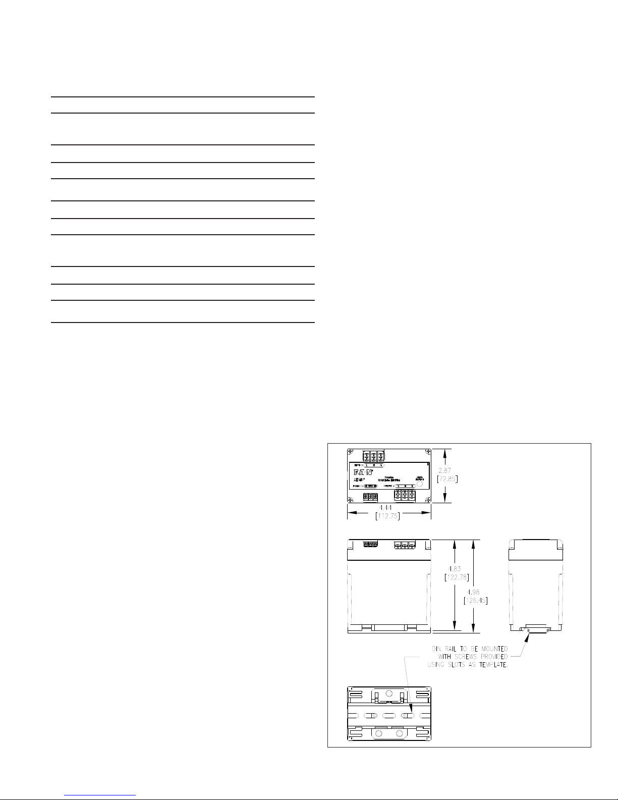
Figure 1. Aegis PH Dimensions.
EATON www.eaton.com
3
 Loading...