

Page 1
CN 中国的: “如果有必要,請問您的代理庫珀卡普里SAS這些指令的另
一種語言”
CZ český:"Tento návod k použití si můžete vyžádat ve svém mateřském jazyce u
příslušného zastoupení společnosti Cooper Capri SAS ve vaší zemi."
DK dansk:"Montagevejledningen kan oversættes til andre EU-sprog og rekvireres
hos Deres Cooper Capri SAS leverandør"
EE Estonian:"Seda kasutusjuhendit oma riigikeeles võite küsida oma riigis asuvast
asjaomasest Cooper Capri SAS esindusest."
ES Español:"En caso necesario podrá solicitar de su representante Cooper Capri
SAS estas instrucciones de servicio en otro idioma de la Union Europea"
FI suomi:"Tarvittaessa tämän käyttöohjeen käännös on saatavissa toisella EU:n
kielellä Teidän Cooper Capri SAS - edustajaltanne"
GR ελληνικά: «Εάν είναι απαραίτητο, να ζητήσει από τον πράκτορά σας Cooper Capri
SAS αυτές τις οδηγίες σε μια άλλη γλώσσα της Ευρωπαϊκής Κοινότητας"
HU magyar:"A kezelési útmutatót az adott ország nyelvén a Cooper Capri SAS
cég helyi képviseletén igényelheti meg."
IT italiano:"Se desiderate la traduzione del manuale operativo in un´altra lingua della
Comunit à Europea potete richiederla al vostro rappresentante Cooper Capri SAS"
LT Lietuvos:"Šios naudojimo instrukcijos, išverstos į Jūsų gimtąją kalbą, galite
pareikalauti atsakingoje Cooper Capri SAS atstovybėje savo šalyje."
LV Latvijas:"Šo ekspluatācijas instrukciju valsts valodā varat pieprasīt jūsu valsts
atbildīgajā Cooper Capri SAS pārstāvniecībā."
MT Malti:"Jistgħu jitolbu dan il-manwal fil-lingwa nazzjonali tagħhom mingħand ir-
rappreżentant ta' Cooper Capri SAS f'pajjiżhom."
NL Nederlands:"Indien noodzakelijk kan de vertaling van deze gebruiksinstructie in een
andere EU-taal worden opgevraagd bij Uw Cooper Capri SAS vertegenwoordiging"
PL polski:"Niniejszą instrukcję obsługi w odpowiedniej wersji językowej można
zamówić w przedstawicielstwie firmy Cooper Capri SAS na dany kraj."
RU Русский: "Если необходимо, попросите вашего агента Купера Капри SAS
эти инструкции на другом язык
SE svenska:"En översättning av denna montage- och skötselinstruktion till annat EU -
språk kan vid behov beställas från Er Cooper Capri SAS - representant"
SI slovenske:"Navodila za uporabo v Vašem jeziku lahko zahtevate pri pristojnem
zastopništvu podjetja Cooper Capri SAS v Vaši državi.
SK slovenčina:"Tento návod na obsluhu Vám vo Vašom rodnom jazyku poskytne
zastúpenie spoločnosti Cooper Capri SAS vo Vašej krajine."
FRANCAIS
CROUSE-HINDS
SERIES
ADE
Instruction Réglementaire
CAP184249
FR-GB / BR-DE/ KOR édition 2016/06/b- 1/2
Entrées de câbles produites par
COOPER CAPRI SAS
36-40 rue des Fontenils,
41600 Nouan-le-Fuzelier FRANCE
Tel. +33 (0)2 54 83 49 00
Voir Instruction d’Assemblage 2/2, spécifique pour chaque version : ADE-1F2,
ADE-1F2 A, ADE-1F2 DS, ADE-1FC, ADE-4F, ADE-5F, ADE-6F, ADE-6FC
Déclaration de conformité UE / IEC
Les entrées de câbles Ex de type ADE satisfont aux exigences essentielles de santé et
de sécurité de la directive 2014/34/EU “Directive ATEX ” en conformité avec les normes :
- IEC 60079-0:2011& EN 60079-0:2012 Exigences générales
- IEC/EN 60079-1:2014 Enveloppes antidéflagrantes 'd"
- IEC/EN 60079-7:2015 Sécurité augmentée "e"
- IEC/EN 60079-15:2010 Mode de protection "n"
- IEC 60079-31:2013 & EN 60079-31:2014 Protection poussière par enveloppe "t"
Les normes EN 60079-1:2007, EN 60079-7:2007 et EN 60079-31: 2009 utilisées pour la
certification ont été comparées aux dernières versions en vigueur : les entrées de câbles
Ex de type ADE ne sont impactées par aucune modification technique majeure.
Elles sont prévues pour une utilisation dans les zones suivantes :
Zones 1 et 2, en atmosphères explosives gazeuses, sur des équipements électriques de
Groupe I (Mine) ; et Groupes IIA, IIB et IIC,
Zones 21 and 22, en atmosphères explosives poussiéreuses, sur des équipements
électriques de Groupes IIIA, IIIB et IIIC
Code de marquage ATEX :
II2GD / Ex db IIC/ Ex eb IIC / Ex tb IIIC
II3G Ex nRc IIC
IM2 Ex db I Ex eb I (pour application mine)
Certificat CE de type N° INERIS12ATEX0032X
Notification Qualité N° LCIE 00 ATEX Q 8005
L'attestation CE de type et la notification qualité ne s'appliquent pas à la catégorie 3.
Code marquage IECEx :
Ex db IIC / Ex eb IIC / Ex nRc IIC / Ex tb IIIC
Ex db I Ex eb I (pour application mine)
certificat IECEx N° IECEx INE 12.0025X
Notification Qualité N° FR/LCI/QAR 07.0002/03
Personne autorisée ATEX Capri, MAUGER, 2016/07
Directive INMETRO n° 179/2010
CEPEL 05.0558X avec câble non armé
CEPEL 05.0559X avec câble MTA, SWA ou tressé
KOSHA AV4BO.0245-0256 et 0479-0494
NANIO-CCVE ТС RU С-FR.ГБ05.В.00858
NEPSI GYJ13.1082X
CCoE NoP360379-1
SABS MS/15-0314X
ABS N°14-HS1274083-PDA
BV 40910/A0 BV
DNV N° TAE000010X
Lloyds N° 11/00072
Entrées de câble prévues pour utilisation en atmosphères potentiellement explosives,
conçues et fabriquées selon le Code électrique américain (NEC) et le Code électrique
canadien (CEC) conformément aux normes UL2225 et C22.2 No 1.
E310130; IP68
Série ADE pour utilisation avec ITC (InstrumentationTray Cable / câble d’instrumentation
pour chemin de câble), MV (Medium Voltage / moyenne tension), PLTC (Power Limited
Tray Cable / câble à puissance limitée pour chemin de câble), TC-ER-HL, TC-ER, TC
(Tray Cable / câble pour chemin de câble).
Zones dangereuses Classe I, Zone 1, AEx e II pour :
- ADE-1F2, -1F2 A, -1F2 DS et 1FC n°3 à n°8, NPT 1/2 à 1"1/4 ou M20 à M40 avec
câble non armé TC-ER-HL de diamètre jusqu’à 1".
Zones dangereuses Classe I, Zone 2, AEx e II, Ex e II pour :
- ADE-1F2, -1F2 A et -1F2 DS n°3 à 17, NPT1/2 à 4" ou M20 à M110 avec câble non
armé ITC, MV, PLTC, TC-ER-HL, TC-ER et TC.
- ADE-4F et -5F n°4 à 17, NPT1/2 à 4" ou M20 à M110 avec câble armé ITC, MV,
PLTC, TC-ER-HL, TC-ER et TC.
- ADE-6F n°5 à 11, NPT1/2 à 2" ou M20 à M63 avec câble armé ITC, MV, PLTC, TCER-HL, TC-ER et TC.
Zones dangereuses Classe I, Zone 2, AEx de II, Ex de II
- ADE-1FC n°4 à 16, NPT1/2 à 4" ou M20 à M110 avec câble non armé ITC, MV,
PLTC, TC-ER-HL, TC-ER, TC et compound TSC.
- ADE-6FC n°5 à 17, NPT1/2 à 4" ou M20 à M110 avec câble armé ITC, MV, PLTC,
TC-ER-HL, TC-ER, TC et compound TSC.
Zones dangereuses Classe I, Division 1, Groupes A, B, C et D pour :
- ADE-1FC n°4 à 9, NPT1/2 à 1”1/4 ou M20 à M40 avec câble TC-ER-HL, ITC-HL et
compound TSC.
- ADE-6FC n°5 à 9, NPT1/2 à 1”1/4 ou M20 à M40 avec câble TC-ER-HL, ITC-HL et
compound TSC
Zones dangereuses Classe I, Division 2, Groupes A, B, C et D pour :
- ADE-1FC n°4 à 16, NPT1/2 à 4" ou M20 à M110 avec câble non armé PLTC, PLTCER, ITC, ITC-ER, TC, TC-ER et compound TSC.
- ADE-6FC n°5 à 17, NPT1/2 à 4" ou M20 à M110 avec câble armé PLTC, PLTC-ER,
ITC, ITC-ER, TC, TC-ER et compound TSC.
E314047; IP68
Zones dangereuses Classe I, Zone 2, AEx e II, Ex e II pour :
- ADE-1F2, -1F2 A et -1F2 DS n°3 à 17, NPT1/2 à 4" ou M20 à M110 avec câble
Marine non armé.
Zones dangereuses Classe I, Zone 1, AEx e II, Ex e II pour:
- ADE-4F et -5F n°4 à 17, NPT1/2 à 4" ou M20 à M110 avec câble Marine armé.
- ADE-6F n°5 à 11, NPT1/2 à 2" ou M20 à M63 avec câble Marine armé.
Le marquage Zone 1 et 2 permet l’installation dans toutes les atmosphères gazeuses
autorisées par l'article 505 du code NEC et la section 18 du code CEC.
En application de l’article NEC 501.5, les entrées de câble disposant du marquage zone 1
ou zone 2 sont utilisables en Division 2 pourvu qu’elles soient montées sur des
enveloppes ne produisant pas de sources d’inflammation en service normal.
E324850; IP68
Zones dangereuses Classe I, Division 2, Groupes A, B, C et D pour :
- ADE-1FC n°4 à 16, NPT1/2 à 4" ou M20 à M110 avec câble Marine non armé, et
compound TSC.
Zones dangereuses Classe I, Division 1, Groupes A, B, C and D pour :
- ADE-6FC n°5 à 17, NPT1/2 à 4" ou M20 à M110 avec câble Marine armé et
compound TSC.
Le marquage marine Div1 et 2 permet l'installation dans toutes les atmosphères gazeuses
autorisées par l'article 111.60 de la règlementation en génie électrique des gardes côtes
des États-Unis, sous-Chapitre J (titre 46 de la réglementation fédérale, parties 110 à 113
incluses) norme électrique régissant les Navires, TP 127F, article 26, paragraphes 7 (a) et
7 (b).
1. Exigences d'installation :
1,1. Exigences générales Ex :
a La sélection et le montage doivent être effectués uniquement par un
personnel qualifié Ex
b Les câbles doivent être gainés d'une matière thermoplastique,
thermodurcissable ou élastomère. Ils doivent être ronds, compacts, avoir un
matelas et un bourrage extrudés, le cas échéant ne pas être hygroscopiques.
c Les câbles doivent être sélectionnés selon leur capacité à réduire les effets
du fluage à froid « coldflow ».
d Les câbles à faible résistance à la traction (communément appelés « easy
tear ») ne doivent pas être utilisés en zones dangereuses sauf s'ils sont dans
des conduits.
e Les entrées de câble équipées d'un dispositif d'amarrage qui serre la tresse
ou l'armure du câble peuvent être utilisées pour fournir la liaison
équipotentielle.
f Les entrées de câbles à filetages coniques ne doivent pas être utilisées sur
des enveloppes ayant des entrées non filetées ; les filetages coniques
incluent les filetages NPT.
g Un lubrifiant adapté peut être utilisé sur les filetages, à condition qu'il soit
non-durcissant, non métallique et non-combustible et que toute mise à la
terre soit conservée.
1.2. Exigences supplémentaires pour «d» :
Dans le cas d’utilisation de la norme EN/IEC 60079-14 pour l’installation,
veuillez suivre les recommandations afférentes à la sélection et à l'utilisation
des entrées de câble.
2 Règles de construction :
2.1 Étanchéité du câble :
- Les ADE-1F2, 1F2 A, 1F2 DS, 4F, 5F et 6F n'admettent qu'une seule bague
d'étanchéité interne spécifique en élastomère. Cette bague non comprimée a
une hauteur axiale minimale de 5 mm.
- Les ADE-1FC et 6FC assurent l’étanchéité interne par compound.
- Tous les ADE assurent un IP68 avec le câble.
2.2 Fixation à l’équipement :
Le filetage de fixation peut être réalisé comme suit :
- Métrique selon ISO 965-1 et 965-3, qualité moyenne ou fine, permettant une
profondeur de vissage d’au moins 8mm et 5 filets engagés, selon EN et CEI
60079-1.
- NPT selon ANSI/ASME B1.20.1. avec L2 et L4 selon EN et CEI 60079-1,
permettant plus de 4,5 filets engagés.
2.3 Indice de Protection avec l’enveloppe "IP":
2.3.1. Minimum requis :
- IP54 pour Groupes I et II, protection "d", "e", "i", "m", "n", "o", “p” et "q".
- IP6X pour Groupe IIIC, EPL Dc, protection "t", "i", "m" et "p".
2.3.2 Version filetage Métrique certifiée :
- Installé sur équipement avec surface de contact plane, sur trou fileté, ou sur
trou lisse (utilisation “d” exclue) fixé par un écrou qualifié avec tous les filets
engagés :
* IP64 et IP66 sans joint plat, monté sur trou lisse et surface Ra 0,4µm ou
monté sur trou fileté et surface Ra 1,6µm maxi.
* IP64 et IP66 avec tous les joints plats Capri (Fibre Rouge, Fibre Verte,
Néoprène, Nylon ou PTFE) sur surface Ra 6.3μm maxi.
* IP68 testé 30m/7jours avec joint plat Capri Fibre Rouge ou Fibre Verte sur
surface Ra 6.3μm maxi.
- La longueur de l'entrée filetée permet de respecter l'engagement de filetage
applicable avec l'ajout d'un joint-plat (épaisseur 1,5 ou 2mm) entre le presseétoupe et l’enveloppe.
- Sur équipement avec trou fileté ou lisse, un ADE spécifique avec un joint Oring intégré dans une gorge d’un corps spécifique permet IP68.
2.3.3 Version filetage NPT certifiée ;
Toujours sur équipement avec trou fileté, testée IP66 et IP68 30m/7jours. Le
lubrifiant Crouse Hinds de type HTL peut être nécessaire.
2.3.4 Les conditions spécifiques IP68 sont soumises à un accord entre Capri
et l'utilisateur.
2.3.5 Ces entrées de câble permettent l’utilisation avec appareil à respiration
limitée, type de protection "nR".
3. Marquage :
3.1 Marquage des entrées de câble :
- Toutes les informations Ex sont marquées sur le corps et/ou sur le chapeau.
- Lorsque la place est limitée le Symbole Ex + Mode de protection + Groupe ne
sont pas marqués.
- Le marquage de la classe de température et du numéro de fabrication ne
sont pas nécessaires pour les entrées de câble.
- Les entrées de câble marquées "d" conviennent pour "d", "e", "ia", "ib", "ic",
"ma", "mb", "mc", "nA", "nC", "nR, "o", “pv”, "px", "py", "pz" et "q".
- Les entrées de câble marquées "tb" conviennent pour "tb", "tc", "ia", "ib",
"ma", "mb", "mc" et "p".
- Les entrées de câble marquées «IIC» conviennent pour «IIA» et «IIB».
- Les entrées de câble marquées «IIIC» conviennent pour «IIIA» et «IIIB».
3.2 Marquage des bagues d'étanchéité :
- Le numéro marqué sur la bague définit le diamètre minimum et maximum des
câbles permis.
- Le marquage des bagues d'étanchéité permet de déterminer l'utilisation
appropriée : ADE 7e et 8i = bague utilisable pour gaine externe de câble sur
ADE n°7 et pour gaine interne de câble sur ADE n°8
- Pour les ADE-1F2, 4F et 5F la plage de température est définie par la couleur
de la bague :
. -30 +80°C avec bague d’étanchéité Noire
. -60 +140°C avec bague d’étanchéité Rouge ou Gris
4. Recommandation pour assembler les ADE :
- Utiliser des gants pour manipuler les produits.
- Vérifier si la taille de l’entrée de câble (N° marqué sur l’entrée de câble) est
adaptée à toutes les dimensions du câble, voir tableau sur l’instruction
d’assemblage.
- Vérifier si le type et la taille du filetage de queue, marqués sur le corps, sont
adaptés à l’équipement.
- Pour les versions en Aluminium et en acier inoxydable, un lubrifiant adapté
(non-durcissant, non métallique, non combustible et permettant de maintenir
la mise à la terre) doit être utilisée sur tous les filetages. Ce peut être un
lubrifiant Cooper Crouse Hinds de type HTL.
- Pendant l’assemblage la température ne doit pas être inférieure à +10°C
- A basse température les bagues d’étanchéité durcissent, il peut être
nécessaire de les malaxer jusqu’à ce qu’elles deviennent suffisamment
souples.
- Le TSC Compound doit être malaxé environ 3 minutes pour obtenir un
mélange vert uniforme sans veine. Ensuite, le temps de travail est de 45 à 60
min à 20°C, ou de 20 à 30 min à 30°C.
5. Maintenance:
À chaque inspection de l'équipement, vérifier les entrées de câble selon
60079-17. Si le câble se déplace, serrer les chapeaux. Si le serrage est
inefficace remplacer les entrées de câble
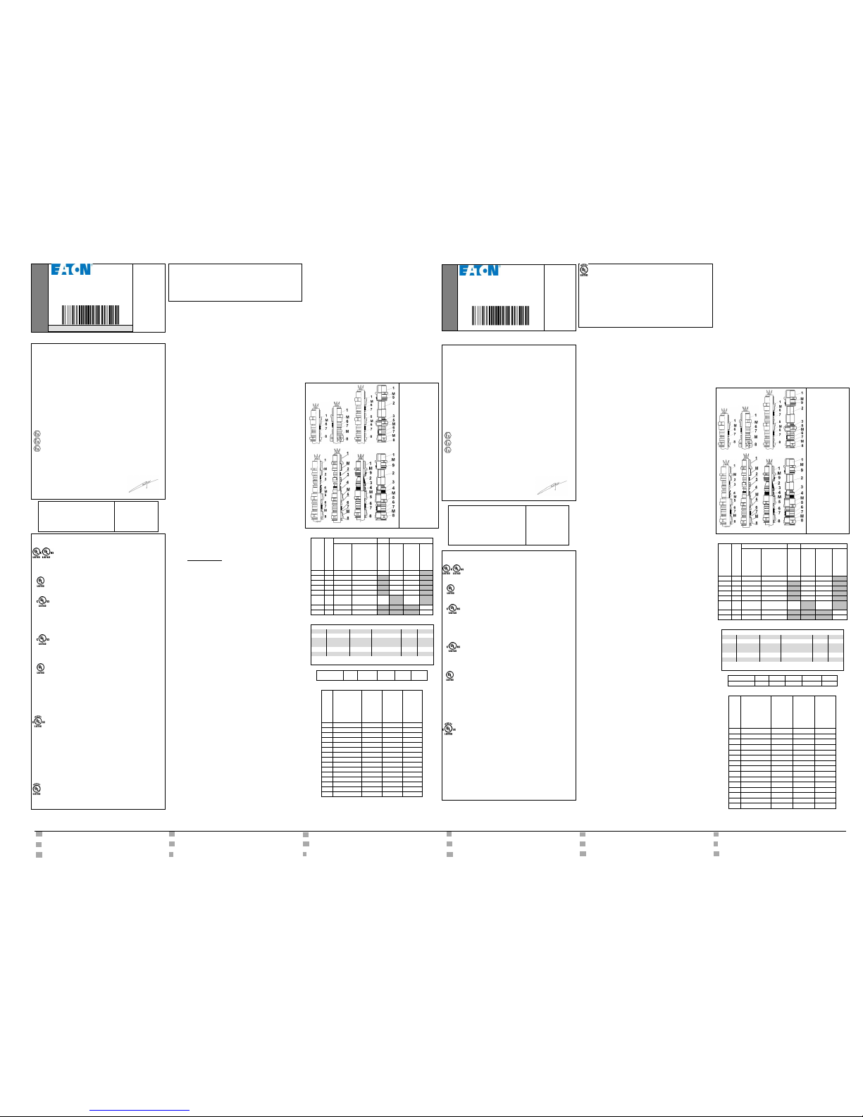
ADE-1F2 ADE-1F2 A ADE-1F2 DS ADE-1FC
ADE-4F ADE-5F ADE-6F ADE-6FC
M : Marquage
1 : Corps
2 : Bague Etanchéité
Interne où
Chambre compound
3 : Bague de
compression (Fouloir)
4 : Bague d’amarrage
5 : Chapeau Interne
6 : Bague Etanchéité
Externe
7 : Rondelle de
glissement (Grain)
8 : Chapeau Externe
9 : Bague Déluge
PARAMETRES RELATIFS A LA SECURITE :
ADE - version
Taille n°
Joint fileté
Ex
Température Service °C
Cylindrique
(mini UL M20)
conique
(mini UL NPT1/2")
Amarrage câble
nécessaire
Bague Néoprène
Bague Silicone
TSC Compound
***
1F2
3à17
M10àM110
NPT1/8"àNPT4" -30à+80
-60à+140
1F2 A
3à17
M10àM110
NPT1/8"àNPT4" -30à+80
-60à+140
1F2 DS
3à17
M10àM110
NPT1/8"àNPT4" -30à+80
-60à+140 4F
4à17
M10àM110
NPT1/8"àNPT4" -30à+80
-60à+140
5F
4à17
M10àM110
NPT1/8"àNPT4" -30à+80
-60à+140
6F
5à11
M16àM63
NPT3/8"àNPT2"
câble
blindé
-60à+80
1FC
4à16
M16àM110
NPT3/8"àNPT4" -60à+80
6FC
5à17
M16àM110
NPT3/8"àNPT4" -60à+80
*** -20 à +40°C avec certificat E324850 UL.
ATEX et IECEx Utilisation Gr.I "Mine" :
Model(1)
ADE-1F2 A
ADE-1F2 DS
ADE-4F et ADE-5F
ADE-1FC
ADE-6FC
Metal(2)
(3,4)
(5)
(3,4)
(5)
(3,4)
(5)
(3,4,5)
(3,4,5)
ISO
M32M110
M16M110
M32M110
M32M110
M25M110
M16M110
M63-
M110
M50-
M110
NPT
1”-4”
3/8”-4”
1”-4”
1”-4”
3/4”-4”
3/8”-4”
2”-4”
2”-4”
Size n°
8-17
4-17
8-17
8-17
8-17
4-17
11-16
11-17
(1) ADE-1F2 et 6F jamais Gr.I "Mine" ; (2) Aluminium jamais Gr.I "Mine" pour tous les ADE ;
(3) Laiton ; (4) Bronze ; (5) Acier Inoxydable.
Joint plat
Nylon
Fibre rouge
Néoprène
Fibre vert
PTFE
Température °C
-30 +75
-30 +80
-40 +80
-60 +140
-60 +140
TABLEAU D’UTILISATION DES CABLES :
Taille N°
ADE-1F2
Diamètre externe
Câble / mm
ADE-4F, 5F, 6F
Diamètre externe
Câble / mm
ADE-1FC, 6FC
Diamètre externe
Câble / mm
Epaisseur Armure ou
tresse / mm
3
2.75 - 5.5
2.75 - 5.5
2.75 - 5.5
4
4.5 - 8.5 (8)
4.5 - 8.5
4 - 8.5
0.2 - 0.9
5
7 - 12
7 - 12
6 - 12
0.2 - 0.9 6 10 - 16 (15.5)
10 - 16
8.5 - 16
0.2 - 1.25 7 13.5 - 21 (20.5)
13.5 - 21
12 - 21
0.2 - 1.25
8
18 - 27.5 (26)
18 - 27.5
16 - 27.5
0.2 - 1.6 9 23 - 34
23 - 34
21 - 34
0.2 - 1.6
10
29 - 41
29 - 41
27 - 41
0.2 - 2
11
35 - 48 (45)
35 - 48
33 - 48
0.2 - 2.5
12
42 - 56 (53)
42 - 56
40 - 56
0.2 - 2.5
13
50 - 65 (62.5)
50 - 65
47 - 65
0.2 - 2.5
14
58 - 74 (73)
58 - 74
54 - 74
0.2 - 2.5
15
66 - 83 (78)
66 - 83
63 - 83
0.2 - 3.15
16
75 - 93 (92)
75 - 93
72 - 93
0.2 - 3.15
17
85 - 104
85 - 104
85 - 104
0.2 - 3.15
ENGLISH
CROUSE-HINDS
SERIES
ADE
Regulatory Instruction
CAP184249
FR-GB / BR-DE/ KOR édition 2016/06/b- 1/2
Cable glands produced by
COOPER CAPRI SAS
36-40 rue des Fontenils,
41600 Nouan-le-Fuzelier FRANCE
Tel. +33 (0)2 54 83 49 00
See the Assembly Instruction 2/2, specific for each version: ADE-1F2,
ADE-1F2 A, ADE-1F2 DS, ADE-1FC, ADE-4F, ADE-5F, ADE-6F, ADE-6FC
EU / IEC Declaration of conformity
ADE Ex cable gland type satisfy the Essential Health and Safety requirements of the
2014/34/EU directive “ATEX Directive” in compliance with standards:
- IEC 60079-0:2011& EN 60079-0:2012 General requirements
- IEC/EN 60079-1:2014 Flameproof enclosures "d"
- IEC/EN 60079-7:2015 Increased safety "e"
- EN 60079-15:2010 Type of protection "n"
- IEC 60079-31:2013 & EN 60079-31:2014 Dust protection enclosure "t"
EN 60079-1:2007, EN 60079-7:2007 and EN 60079-31:2009 standards used for
certification has been compared to latest versions: no major technical change applies to
ADE Ex cable glands.
Intended for use in:
Zones 1 and 2, in explosive gas atmospheres, on electrical equipment Group I (Mining);
and Groups IIA, IIB and IIC
Zones 21 and 22, in explosive dust atmospheres, on electrical equipment Groups IIIA,
IIIB and IIIC
ATEX Marking code:
II2GD / Ex db IIC/ Ex eb IIC / Ex tb IIIC
II3G Ex nRc IIC
IM2 Ex db I Ex eb I (for mining application)
EC type certificate N° INERIS12ATEX0032X
Quality notification N° LCIE 00 ATEX Q 8005
EC type certificate and Quality notification does not apply to category 3.
IECEx Marking code:
Ex db IIC / Ex eb IIC / Ex nRc IIC / Ex tb IIIC
Ex db I Ex eb I (for mining application)
IECEx certificate N° IECEx INE 12.0025X
Quality notification N° FR/LCI/QAR 07.0002/03
Capri ATEX authorized person, MAUGER, 2016/07
Directive INMETRO n° 179/2010
CEPEL 05.0558X with unarmored cable
CEPEL 05.0559X with MTA, SWA or Braided Cable
CCoE NoP360379-1
KOSHA AV4BO.0245-0256 and 0479-0494
NANIO-CCVE ТС RU С-FR.ГБ05.В.00858
NEPSI GYJ13.1082X
SABS MS/15-0314X
ABS N°14-HS1274083-PDA
BV 40910/A0 BV
DNV N° TAE000010X
Lloyds N° 11/00072
Cable fitting intended for use in potentially explosive atmospheres, designed and
constructed with respect to the US National Electrical Code (NEC) and Canadian Electrical
Code (CEC) in compliance with Standards UL2225 and C22.2 No 1:
E310130; IP68
ADE series for use with ITC (Instrumentation-Tray-Cable), MV (Medium Voltage cable),
PLTC (Power-Limited-Tray-Cable), TC-ER-HL, TC-ER, TC (Tray Cable).
Class I, Zone 1, AEx e II Hazardous Locations for :
- ADE-1F2, -1F2 A, -1F2 DS and 1FC n°3 to n°8, NPT1/2 to 1”1/4 or M20 to M40 with
unarmored cable TC-ER-HL up to diameter 1 inch.
Class I, Zone 2, AEx e II, Ex e II Hazardous Locations for:
- ADE-1F2, -1F2 A and -1F2 DS n°3 to 17, NPT1/2 to 4" or M20 to M110 with
unarmored cable ITC, MV, PLTC, TC-ER-HL, TC-ER and TC.
- ADE-4F and -5F n°4 to 17, NPT1/2 to 4" or M20 to M110 with armored cable ITC, MV,
PLTC, TC-ER-HL, TC-ER and TC.
- ADE-6F n°5 to 11, NPT1/2 to 2" or M20 to M63 with armored cable ITC, MV, PLTC,
TC-ER-HL, TC-ER and TC.
Class I, Zone 2, AEx de II, Ex de II
- ADE-1FC n°4 to 16, NPT1/2 to 4" or M20 to M110 with unarmored cable ITC, MV,
PLTC, TC-ER-HL, TC-ER, TC and TSC compound.
- ADE-6FC n°5 to 17, NPT1/2 to 4" or M20 to M110 with armored cable ITC, MV, PLTC,
TC-ER-HL, TC-ER, TC and TSC compound.
Class I, Division 1, Groups A, B, C and D Hazardous Locations for:
- ADE-1FC n°4 to 9, NPT1/2 to 1”1/4 or M20 to M40 with TC-ER-HL, ITC-HL cable and
TSC compound.
- ADE-6FC n°5 to 9, NPT1/2 to 1”1/4 or M20 to M40 with TC-ER-HL, ITC-HL cable and
TSC compound
Class I, Division 2, Groups A, B, C and D Hazardous Locations for:
- ADE-1FC n°4 to 16, NPT1/2 to 4" or M20 to M110 with unarmored cable PLTC, PLTCER, ITC, ITC-ER, TC, TC-ER and TSC compound.
- ADE-6FC n°5 to 17, NPT1/2 to 4" or M20 to M110 with armored cable PLTC, PLTCER, ITC, ITC-ER, TC, TC-ER and TSC compound.
E314047; IP68
Class I, Zone 2, AEx e II, Ex e II Hazardous Locations for:
- ADE-1F2, -1F2 A and -1F2 DS n°3 to 17, NPT1/2 to 4" or M20 to M110 with
unarmored marine shipboard cable.
Class I, Zone 1, AEx e II, Ex e II Hazardous Locations for:
- ADE-4F and -5F n°4 to 17, NPT1/2 to 4" or M20 to M110 with armored marine
shipboard cable.
- ADE-6F n°5 to 11, NPT1/2 to 2" or M20 to M63 with armored marine shipboard cable.
The Zone1 and 2 marking allow installation in all gas atmospheres allowed by Article 505
of the NEC and section 18 of CEC.
Per the NEC, 501.5, zone 1or 2 cable glands are permitted in a Division 2 location for nonsparking and arching applications.
E324850; IP68
Class I, Division 2, Groups A, B, C and D Hazardous Locations for:
- ADE-1FC n°4 to 16, NPT1/2 to 4" or M20 to M110 with unarmored marine shipboard
cable and TSC compound.
Class I, Division 1, Groups A, B, C and D Hazardous Locations for:
- ADE-6FC n°5 to 17, NPT1/2 to 4" or M20 to M110 with armored marine shipboard
cable and TSC compound
The Div1 and 2 marine marking allow installation in all gas atmospheres allowed by
Subpart 111.60 of the United States Coast Guard Electrical Engineering Regulations,
Subchapter J (Title 46 of Federal Regulations, Parts 110 to 113 inclusive) Ships
Electrical Standards, TP 127E, Section 26, Subsections 7(a) and 7(b)
1. Installation requirements:
1.1. Ex General Requirements:
a The selection and the mounting of equipment shall be carried out only by Ex
qualified persons.
b Cables shall be sheathed with thermoplastic, thermosetting, or elastomeric
material. They shall be circular, compact, have extruded bedding and fillers,
if any shall be non-hygroscopic.
c Cables shall be selected to reduce the effects of coldflow characteristic.
d Cables with low tensile strength sheaths (commonly known as ‘easy tear’
cables) shall not be used in hazardous locations unless installed in conduit.
e Cable glands which incorporate a clamping device which clamps the cable
braid or armor can be used to provide the equipotential bonding.
f Cable glands with tapered threads shall not be used in enclosures having
gland plates with unthreaded entries; tapered threads include NPT threads.
g Suitable lubricant may be used on the threads, provided it is non-setting,
non-metallic and non-combustible and any earthing is maintained.
1.2. Additional requirements for «d»:
In case of using EN/IEC 60079-14 for the design, selection and erection of
electrical installations please follow the recommendations regarding the
selection and use of cables and cable glands.
2. Constructional requirements:
2.1. Cable sealing:
- The ADE-1F2, 1F2 A,1F2DS, 4F, 5F and 6F can accept only one specific
elastomeric sealing ring. This ring has a minimal uncompressed axial height
of 5mm.
- The ADE-1FC and 6FC ensures the Internal sealing by compound.
- All the ADE ensures IP68 with the cable.
2.2. Assembling with enclosure:
The entry thread can be manufactured as follows:
- Metric according to ISO 965-1 and ISO 965-3, medium or fine quality,
providing thread depth of at least 8 mm and 5 engaged threads following EN
and IEC 60079-1.
- NPT according to ANSI/ASME B1.20.1, with L2 and L4 in accordance with
EN and IEC 60079-1, providing greater than 4.5 fully engaged threads.
2.3. Protection with enclosure “IP”:
2.3.1. Minimum required:
- IP54 for Groups I and II, protection "d", "e", "i", "m", "n", "o", “p” and "q".
- IP6X for Group IIIC, EPL Dc, protection "t", "i", "m" and "p".
2.3.2. ADE Metric threaded version certified:
- Fitted on equipment with planar contact surface, on threaded hole, or on
blank hole (“d” use excluded) fixed by a qualified locknut with all threads
engaged:
* IP64 and IP66 without Sealing Washer, fitted on blank hole and surface Ra
0,4µm or on threaded hole and surface RA 1,6µm maxi.
* IP64 and IP66 with all Capri Sealing Washers (Red Fiber, Green Fiber,
Neoprene, Nylon or PTFE) on surface Ra 6.3µm maxi.
* IP68 tested 30m/7days with Red Fiber or Green Fiber Capri Sealing
Washers on surface Ra 6.3µm maxi.
- The threaded entry length permit to meet the applicable thread engage with
the add of gasket (thickness 1,5 or 2 mm) between the cable gland and the
enclosure.
- On equipment with threaded or blank hole, a specific ADE with an O-ring
embedded in a groove of a specific body can provide IP68.
2.3.3. ADE NPT threaded version certified:
Always on equipment with threaded hole, tested IP66 and IP68 30m/7days.
Crouse Hinds lubricant HTL type may be necessary.
2.3.4. IP68 specific conditions are subject to an agreement between Capri and
user.
2.3.5. These cable glands permit using with restricted breathing apparatus,
type of protection "nR".
3. Marking:
3.1. Cable gland marking:
- All Ex information marked on the gland body and or cap.
- Where limited space the Symbol Ex + Type of protection + Group are not
marked.
- Cable glands need not to be marked with the temperature class and serial
number.
- Cable glands marked "d" are suitable for "d", "e", "ia", "ib", "ic", "ma", "mb",
"mc", "nA", "nC", "nR, "o", “pv”, "px", "py", "pz" and "q".
- Cable glands marked "tb", suitable for "tb", "tc", "ia", "ib", "ma", "mb", "mc"
and "p".
- Cable glands marked «IIC» are suitable for «IIA» and «IIB».
- Cable glands marked «IIIC» are suitable for «IIIA» and «IIIB».
3.2. Marking for sealing ring:
- The size number marked on the ring defines minimum and maximum
diameters of permitted cables.
- The marking of the sealing rings specify suited use; example ADE 7e and 8i:
Ring for use on external sheath of cable with ADE n°7 and on internal sheath
of cable with ADE n°8:
- For ADE-1F2, 4F and 5F, the ring color determines the temperature range:
. Black color ring: -30 +80°C
. Red or grey color ring: -60 +140°C
4. Recommendation for ADE assembly:
- Use gloves when handling the products.
- Check if the size of the cable gland (N° marked on cable gland) is adapted to
all the dimensions of the cable, see table on the assembly instruction.
- Check if the type and size of the entry thread (marked on the Body) is well
adapted for the equipment.
- For Aluminum and Stainless Steel version, suitable grease must be used on
all the threads. Suitable grease must be non-setting, non-metallic, noncombustible and maintaining earthing. It can be Cooper Crouse Hinds type
HTL lubricants.
- During assembly, the temperature should not be less than +10°C.
- At low temperature the sealing rings harden, it may be necessary to knead
them until they are sufficiently flexible.
- TSC Compound shall be mixed about 3 min to get uniform green, streak-free.
Then the working time is 45 – 60 min at 20°C or 20 – 30 min at 30°C.
5. Maintenance:
At each inspection on the equipment, verify the cable glands according to
60079-17. If the cable moves, tighten the Caps. If the tightening is ineffective
replace the cable glands.
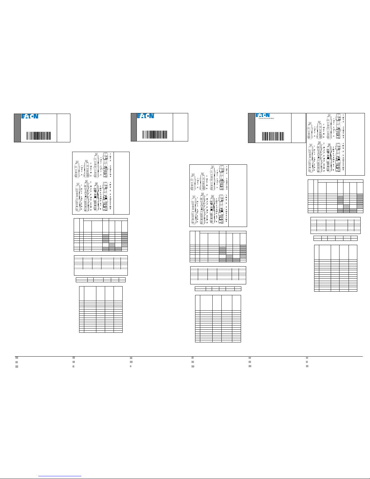
ADE-1F2 ADE-1F2 A ADE-1F2 DS ADE-1FC
ADE-4F ADE-5F ADE-6F ADE-6FC
M : Marking
1 : Body
2 : Internal Sealing ring or
Compound chamber
3 : Compression ring
4 : Clamping ring
5 : Internal cap
6 : External sealing ring
7 : Skid washer
8 : External cap
9 : Deluge ring
PARAMETERS RELATING TO THE SAFETY:
ADE - version
Size n°
Threaded joint
Ex
Service Temperature °C
Cylindrical
(mini UL M20)
conical
(mini UL NPT1/2")
Cable clamping
required
Neoprene ring
Silicone ring
TSC Compound
***
1F2
3to17
M10toM110
NPT1/8"toNPT4" -30to+80
-60to+140
1F2 A
3to17
M10toM110
NPT1/8"toNPT4" -30to+80
-60to+140 1F2 DS
3to17
M10toM110
NPT1/8"toNPT4" -30to+80
-60to+140
4F
4to17
M10toM110
NPT1/8"toNPT4" -30to+80
-60to+140
5F
4to17
M10toM110
NPT1/8"toNPT4" -30to+80
-60to+140
6F
5to11
M16toM63
NPT3/8"toNPT2"
braided
cable
-60to+80
1FC
4to16
M16toM110
NPT3/8"toNPT4" -60to+80
6FC
5to17
M16toM110
NPT3/8"toNPT4" -60to+80
*** -20 to +40°C with certificate E324850 UL.
ATEX and IECEx Gr.I "Mine" use:
Model(1)
ADE-1F2 A
ADE-1F2 DS
ADE-4F and ADE-5F
ADE-1FC
ADE-6FC
Metal(2)
(3,4)
(5)
(3,4)
(5)
(3,4)
(5)
(3,4,5)
(3,4,5)
ISO
M32M110
M16-
M110
M32M110
M32M110
M25-
M110
M16-
M110
M63M110
M50M110
NPT
1”-4”
3/8”-4”
1”-4”
1”-4”
3/4”-4”
3/8”-4”
2”-4”
2”-4”
Size n°
8-17
4-17
8-17
8-17
8-17
4-17
11-16
11-17
(1) ADE-1F2 and 6F never Gr.I "Mine"; (2) Aluminum material never Gr.I "Mine" for all ADE;
(3) Brass; (4) Bronze; (5) Stainless Steel.
Gasket
Nylon
Red fiber
Neoprene
Green fiber
PTFE
Temperature °C
-30 +75
-30 +80
-40 +80
-60 +140
-60 +140
TABLE FOR USE ON CABLE:
Size N°
ADE-1F2
outer diameter
Cable / mm
ADE-4F , 5F, 6F
outer diameter
Cable / mm
ADE-1FC, 6FC
outer diameter
Cable / mm
Armor or braid
thickness / mm
3
2.75 - 5.5
2.75 - 5.5
2.75 - 5.5
4
4.5 - 8.5 (8)
4.5 - 8.5
4 - 8.5
0.2 - 0.9
5
7 - 12
7 - 12
6 - 12
0.2 - 0.9
6
10 - 16 (15.5)
10 - 16
8.5 - 16
0.2 - 1.25
7
13.5 - 21 (20.5)
13.5 - 21
12 - 21
0.2 - 1.25
8
18 - 27.5 (26)
18 - 27.5
16 - 27.5
0.2 - 1.6 9 23 - 34
23 - 34
21 - 34
0.2 - 1.6
10
29 - 41
29 - 41
27 - 41
0.2 - 2
11
35 - 48 (45)
35 - 48
33 - 48
0.2 - 2.5
12
42 - 56 (53)
42 - 56
40 - 56
0.2 - 2.5
13
50 - 65 (62.5)
50 - 65
47 - 65
0.2 - 2.5
14
58 - 74 (73)
58 - 74
54 - 74
0.2 - 2.5
15
66 - 83 (78)
66 - 83
63 - 83
0.2 - 3.15
16
75 - 93 (92)
75 - 93
72 - 93
0.2 - 3.15
17
85 - 104
85 - 104
85 - 104
0.2 - 3.15
Page 2
CN 中国的: “如果有必要,請問您的代理庫珀卡普里SAS這些指令的另
一種語言”
CZ český:"Tento návod k použití si můžete vyžádat ve svém mateřském jazyce u
příslušného zastoupení společnosti Cooper Capri SAS ve vaší zemi."
DK dansk:"Montagevejledningen kan oversættes til andre EU-sprog og rekvireres
hos Deres Cooper Capri SAS leverandør"
EE Estonian:"Seda kasutusjuhendit oma riigikeeles võite küsida oma riigis asuvast
asjaomasest Cooper Capri SAS esindusest."
ES Español:"En caso necesario podrá solicitar de su representante Cooper Capri
SAS estas instrucciones de servicio en otro idioma de la Union Europea"
FI suomi:"Tarvittaessa tämän käyttöohjeen käännös on saatavissa toisella EU:n
kielellä Teidän Cooper Capri SAS - edustajaltanne"
GR ελληνικά: «Εάν είναι απαραίτητο, να ζητήσει από τον πράκτορά σας Cooper Capri
SAS αυτές τις οδηγίες σε μια άλλη γλώσσα της Ευρωπαϊκής Κοινότητας"
HU magyar:"A kezelési útmutatót az adott ország nyelvén a Cooper Capri SAS
cég helyi képviseletén igényelheti meg."
IT italiano:"Se desiderate la traduzione del manuale operativo in un´altra lingua della
Comunit à Europea potete richiederla al vostro rappresentante Cooper Capri SAS"
LT Lietuvos:"Šios naudojimo instrukcijos, išverstos į Jūsų gimtąją kalbą, galite
pareikalauti atsakingoje Cooper Capri SAS atstovybėje savo šalyje."
LV Latvijas:"Šo ekspluatācijas instrukciju valsts valodā varat pieprasīt jūsu valsts
atbildīgajā Cooper Capri SAS pārstāvniecībā."
MT Malti:"Jistgħu jitolbu dan il-manwal fil-lingwa nazzjonali tagħhom mingħand ir-
rappreżentant ta' Cooper Capri SAS f'pajjiżhom."
NL Nederlands:"Indien noodzakelijk kan de vertaling van deze gebruiksinstructie in een
andere EU-taal worden opgevraagd bij Uw Cooper Capri SAS vertegenwoordiging"
PL polski:"Niniejszą instrukcję obsługi w odpowiedniej wersji językowej można
zamówić w przedstawicielstwie firmy Cooper Capri SAS na dany kraj."
RU Русский: "Если необходимо, попросите вашего агента Купера Капри SAS
эти инструкции на другом язык
SE svenska:"En översättning av denna montage- och skötselinstruktion till annat EU -
språk kan vid behov beställas från Er Cooper Capri SAS - representant"
SI slovenske:"Navodila za uporabo v Vašem jeziku lahko zahtevate pri pristojnem
zastopništvu podjetja Cooper Capri SAS v Vaši državi.
SK slovenčina:"Tento návod na obsluhu Vám vo Vašom rodnom jazyku poskytne
zastúpenie spoločnosti Cooper Capri SAS vo Vašej krajine."
PORTUGUÊS
CROUSE-HINDS
SERIES
ADE
Instrução Normativa
CAP184249
FR-GB / BR-DE/ KOR édition 2016/06/b- 1/2
Prensa-cabos produzidos por
COOPER CAPRI SAS
36-40 rue des Fontenils,
Nouan-le-Fuzelier 41600 FRANÇA
Tel. +33 (0)2 54 83 49 00
Veja as instruções de montagem 2/2, específicas para cada versão: ADE-1F2,
ADE-1F2 A, ADE-1F2 DS, ADE-1FC, ADE-4F, ADE-5F, ADE-6F, ADE-6FC
1. Requisitos de instalação:
1.1. Requisitos gerais Ex:
a A seleção e a montagem de equipamento devem ser realizadas somente por
pessoas qualificadas Ex.
b Os cabos devem ser revestidos com material termoplástico, termoconsolidante ou
elastomérico. Eles devem ser circulares, compactos, e se houver estratos e
enchimentos extrusados, eles deverão ser não higroscópicos.
c Os cabos devem ser selecionados para reduzir os efeitos da característica de
circulação a frio.
d Cabos com revestimentos de baixa resistência à tração (comumente conhecidos
por “arrebentam facilmente”) não devem ser utilizados em áreas perigosas, a
menos que instalados em conduítes.
e Prensa-cabos que incorporam um dispositivo de fixação, que prende a trança ou a
blindagem do cabo, podem ser utilizados para fornecer a compensação de
potencial.
f Prensa-cabos com roscas cônicas não devem ser utilizados em recintos que
tenham placas de base com entradas sem rosca;roscas cônicas incluem roscas
NPT.
g Um lubrificante adequado pode ser usado nas roscas, desde que seja não
aderente, não metálico e não combustível e que mantenha o aterramento.
1.2. Requisitos adicionais para «d»:
No caso de utilização de EN/IEC 60079-14 para o projeto, seleção e montagem de
instalações elétricas , siga as recomendações sobre a seleção e uso de cabos e
prensa-cabos.
2. Requisitos de construção:
2.1. Vedação do cabo:
- O ADE-1F2, 4F, 5F e 6F podem aceitar apenas um anel de vedação elastomérico.
Este anel tem uma altura axial descomprimida mínima de 5 mm.
- O ADE-1FC e 6FC garantem a vedação interna pelo composto.
- Todo o ADE garante IP68 com o cabo.
2.2. Montagem com gabinete:
O segmento de entrada pode ser fabricado como se segue:
- Métricas de acordo com ISO 965-1 e ISO 965-3, qualidade média ou fina,
proporcionando profundidade de rosqueamento mínima de 8 mm e 5 filetes
engajados de acordo com EN e IEC 60079-1.
- NPT de acordo com ANSI/ASME B1.20.1, com L2 e L4 em conformidade com EN e
IEC 60079-1, proporcionando mais que 4,5 filetes totalmente engajados.
2.3. Proteção com gabinete "IP":
2.3.1. Requisitos mínimos:
- IP54 para os Grupos I e II, proteção "d", "e", "i", "m", "n", "o", “p” und "q".
- IP6X para o Grupo IIIC, EPL Dc, proteção "t", "i", "m" und "p".
2.3.2. Versão com rosca métrica ADE certificada:
- Equipado em equipamentos com contato planar superfície, em furo roscado, ou em
buraco vazio ("d" uso excluídos) fixada por uma porca de fixação qualificado com
todos filetes engajados:
* IP64 e IP66 sem gaxeta, montado em buraco vazio e superficial Ra 0,4 m ou em
furo roscado e RA superfície 1,6µm maxi.
* IP64 e IP66 com toda Capri gaxeta (Fibra Vermelha, Fibra Verde, Neoprene,
Nylon ou PTFE) e superfície Ra 6.3μm maxi.
* IP68 testado 30m/dias com Fibra Vermelha ou Fibra Verde Capri gaxeta e
superfície Ra 6.3μm maxi.
- O comprimento de entrada de rosca permite o engajamento de filete aplicável com
a adição de uma gaxeta (espessura de 1,5 ou 2 mm) entre o prensa-cabos e o
gabinete.
- Em equipamentos com furo roscado ou furo simples, uma ADE específica com um
anel O embutido em um sulco de um corpo específico pode fornecer IP68.
2.3.3. Versão ADE com rosca NPT certificada:
Sempre em equipamentos com furo roscado, IP66 e IP68 30m/7dias testados.
Crouse Hinds tipo de lubrificante HTL pode ser necessária.
2.3.4. As condições específicas de IP68 estão sujeitas a um acordo entre a Capri e o
usuário.
2.3.5. Estes prensa-cabos permitem o uso com aparelho respiratório restrito, tipo de
proteção "nR".
3. Marcação:
3.1. Marcação de prensa-cabos:
- Todas as informações Ex marcadas no corpo da prensa e/ou tampa.
- Onde o espaço é limitado, o símbolo Ex + Tipo de proteção + Grupo não está
marcado.
- Os prensa-cabos não precisam ser marcados com a classe de temperatura e o
número de série.
- Prensa-cabos marcados com "d" são apropriados para "d", "e", "ia", "ib", "ic", "ma",
"mb", "mc", "nA", "nC", "nR, "o", "pv", "px", "py", "pz" e "q".
- Prensa-cabos marcados com "tb", apropriados para "tb", "tc", "ia", "ib", "ma", "mb",
"mc" und "p".
- Prensa-cabos marcados com «IIC» são adequados para «IIA» e «IIB».
- Prensa-cabos marcados com «IIIC» são adequados para «IIIA» e «IIIB».
3.2. Marcação do anel de vedação:
- O número de tamanho marcado no anel define os diâmetros mínimo e máximo dos
cabos permitidos.
- A marcação dos anéis de vedação especifica o uso adequado; exemplo ADE 7e e
8i: Anel para uso em revestimento externo do cabo com ADE n°7 e em
revestimento interno do cabo com ADE n°8:
- Para ADE-1F2, 4F e 5F, a cor do anel determina a faixa de temperatura:
. Anel em neoprene preto: -30 +80°C
. Anel de silicone vermelho ou cinza: -60 +140°C
4. Recomendação para montagem ADE:
- Use luvas ao manusear os produtos.
- Verifique se o tamanho do prensa-cabos (N° marcado no prensa-cabos) está
adaptado para todas as dimensões do cabo, consulte a tabela nas instruções de
montagem.
- Verifique se o tipo e tamanho do segmeto de entrada (marcados no corpo do
produto) estão bem adaptados para o equipamento.
- Para as versões em alumínio e aço inoxidável, deve-se usar uma graxa apropriada
em todos os segmentos. A graxa adequada deve ser não aderente, não metálica,
não combustível e manter o aterramento. Ela pode ser lubrificantes do tipo HTL da
Cooper Crouse Hinds.
- Durante a montagem, a temperatura não deve ser inferior a 10°C.
- Em baixa temperatura, os anéis de vedação endurecem, e talvez seja preciso
manuseá-los até que estejam suficientemente flexíveis.
- O composto TSC deve ser misturado por cerca de 3 minutos para ficar de uma cor
verde uniforme, sem marcas. Então, o tempo de trabalho é de 45 – 60 min a 20°C
ou 20 – 30 min a 30°C.
5. Manutenção:
Em cada inspeção no equipamento, verifique os prensa-cabos de acordo com
60079-17. Se o cabo se mover, aperte as tampas. Se esse aperto não surtir efeito,
substitua os prensa-cabos.
ADE-1F2 ADE-1F2 A ADE-1F2 DS ADE-1FC
ADE-4F ADE-5F ADE-6F ADE-6FC
M: Marcação
1 : Corpo
2 : Anel de vedação
Interna ou câmara
de composto
3 : Anel de
compressão
4 : Anel de aperto
5 : Tampa interna
6 : Anel de vedação
externa
7 : Arruela de sapata
8 : Tampa externa
9 : Anel de inundação
PARÂMETROS RELACIONADOS À SEGURANÇA:
ADE - versão
Tamanho n°
Junta rosqueada
Ex
Temperatura de serviço °C
Cilíndrico
(mini UL M20)
Cônico
(mini UL NPT1/2")
Fixação de cabo
necessária
Anel de Neoprene
Anel de Silicone
TSC Composa ***
1F2
3a17
M10aM110
NPT1/8"aNPT4" -30a+80
-60a+140
1F2 A
3a17
M10aM110
NPT1/8"aNPT4" -30a+80
-60a+140 1F2 DS
3a17
M10aM110
NPT1/8"aNPT4" -30a+80
-60a+140
4F
4a17
M10aM110
NPT1/8"aNPT4" -30a+80
-60a+140 5F
4a17
M10aM110
NPT1/8"aNPT4" -30a+80
-60a+140
6F
5a11
M16aM63
NPT3/8"aNPT2"
cabo
trançado
-60a+80
1FC
4a16
M16aM110
NPT3/8"aNPT4" -60a+80
6FC
5a17
M16aM110
NPT3/8"aNPT4" -60a+80
*** -20 a +40°C com certificado E324850 UL.
ATEX e IECEx Gr.I "Mining" use:
Modelo(1)
ADE-1F2 A
ADE-1F2 DS
ADE-4F e ADE-5F
ADE-1FC
ADE-6FC
Metal(2)
(3,4)
(5)
(3,4)
(5)
(3,4)
(5)
(3,4,5)
(3,4,5)
ISO
M32-
M110
M16-
M110
M32M110
M32M110
M25-
M110
M16M110
M63-
M110
M50-
M110
NPT
1”-4”
3/8”-4”
1”-4”
1”-4”
3/4”-4”
3/8”-4”
2”-4”
2”-4”
Tamanho n°
8-17
4-17
8-17
8-17
8-17
4-17
11-16
11-17
(1) ADE-1F2 und 6F Nunca Gr.I "Mine";
(2) Material de alumínio não Gr.I "Mine" para todos ADE;
(3) Latão; (4) de bronze; (5) de aço inoxidável.
gaxeta
Nylon
fibra vermelho
Neoprene
fibra verde
PTFE
Température °C
-30 +75
-30 +80
-40 +80
-60 +140
-60 +140
TABELA PARA USO EM CABO:
Tamanho N°
ADE-1F2
diâmetro externo
Cabo / mm
ADE-4F , 5F, 6F
diâmetro externo
Cabo / mm
ADE-1FC, 6FC
diâmetro externo
Cabo / mm
Blindagem ou trança
espessura / mm
3
2,75 - 5,5
2,75 - 5,5
2,75 - 5,5 4
4,5 - 8,5 (8)
4,5 - 8,5
4 - 8,5
0,2 – 0,9
5
7 - 12
7 - 12
6 - 12
0,2 - 0.9 6 10 - 16 (15,5)
10 - 16
8,5 - 16
0,2 – 1,25
7
13,5 - 21 (20,5)
13,5 - 21
12 - 21
0,2 – 1,25 8 18 - 27,5 (26)
18 – 27,5
16 – 27,5
0,2 – 1,6
9
23 - 34
23 - 34
21 - 34
0,2 – 1,6
10
29 - 41
29 - 41
27 - 41
0,2 - 2
11
35 - 48 (45)
35 - 48
33 - 48
0,2 – 2,5
12
42 - 56 (53)
42 - 56
40 - 56
0,2 – 2,5
13
50 - 65 (62,5)
50 - 65
47 - 65
0,2 – 2,5
14
58 - 74 (73)
58 - 74
54 - 74
0,2 – 2,5
15
66 - 83 (78)
66 - 83
63 - 83
0,2 – 3,15
16
75 - 93 (92)
75 - 93
72 - 93
0,2 – 3,15
17
85 - 104
85 - 104
85 - 104
0,2 – 3,15
GERMAN
CROUSE-HINDS
SERIES
ADE
Regulative Vorschrift
CAP184249
FR-GB / BR-DE/ KOR édition 2016/06/b- 1/2
Kabeldurchführungen,
hergestellt von
COOPER CAPRI SAS
36-40 rue des Fontenils,
41600 Nouan-le-Fuzelier FRANCE
Tel. +33 (0)2 54 83 49 00
Siehe die für die jeweilige Version spezifische Montageanleitung 2/2:
ADE-1F2, ADE-1F2 A, ADE-1F2 DS, ADE-1FC, ADE-4F, ADE-5F, ADE-6F, ADE-6FC
1. Installationsanforderungen:
1.1. Ex Allgemeine Anforderungen:
a Auswahl und Montage der Geräte dürfen ausschließlich von qualifiziertem Ex-
Personal durchgeführt werden.
b Die Kabel sind mit thermoplastischem, duroplastischem oder elastomerem Material
zu ummanteln. Sie müssen rund, kompakt, mit extrudierter Bettung und Einlagen
und gegebenenfalls nicht-hygroskopisch ausgeführt sein.
c Die Kabel sind so zu wählen, dass eine Reduzierung der Kaltflusseigenschaften
gewährleistet ist.
d Kabel mit Ummantelungen mit einer geringen Zugfestigkeit (sogenannte Easy-
Tear-Kabel) dürfen in Gefahrenbereichen nicht verwendet werden, es sei denn, sie
werden in Kabelrohren verlegt.
e Kabeldurchführung mit Klemmvorrichtungen, mit denen die Kabelhülle oder
Armierung festgeklemmt wird, können zur Gewährleistung eines
Potentialausgleichs verwendet werden.
f Kabeldurchführungen mit konischem Gewinde dürfen in Gehäusen mit
Anschlussplatten und unbearbeiteten Eingängen nicht verwendet werden; zu
konischen Gewinden zählen NPT-Gewinde.
g Für die Gewinde kann ein geeignetes Schmiermittel verwendet werden,
vorausgesetzt, dieses Mittel ist nicht leitfähig, nicht metallisch, nicht brennbar und
erdungssicher.
1.2. Zusätzliche Voraussetzungen für "d":
Finden Konstruktion, Auswahl und Aufbau der elektrischen Anlagen auf der
Grundlage der EN/IEC 60079-14-Vorschriften statt, halten Sie sich dann bitte an die
Empfehlungen hinsichtlich der Auswahl und Verwendung von Kabeln und
Kabeldurchführungen.
2. Konstruktive Voraussetzungen:
2.1. Kabelabdichtung:
- Laut ADE-1F2, 4F, 5F und 6F ist lediglich ein spezieller elastomerischer Dichtring
zugelassen. Dieser Ring besitzt eine minimale axiale Höhe von 5 mm
unkomprimiert.
- Bei ADE-1FC und 6FC ist eine Innendichtung mittels Dichtmaterial sicher gestellt.
- Alle ADE gewährleisten die Schutzklasse IP68 des Kabels.
2.2. Gehäusemontage:
Das Eingangsgewinde kann wie folgt gefertigt werden:
- Metrische Ausführung laut ISO 965-1 und ISO 965-3, in mittlerer oder hoher
Qualität, mit einer Mindestgewindetiefe von 8 mm und 5 greifenden Gewinden
entsprechend EN und IEC 60079-1.
- NPT in Übereinstimmung mit ANSI/ASME B1.20.1, mit L2 und L4 entsprechend EN
und IEC 60079-1, mit mehr als 4,5 voll greifenden Gewinden.
2.3. Schutzklasse mit Gehäuse “IP”:
2.3.1. Mindestanforderungen:
- IP54 für Gruppen I und II, Schutzklassen "d", "e", "i", "m", "n", "o", “p” und "q".
- IP6X für Gruppe IIIC, EPL Dc, Schutzklassen "t", "i", "m" und "p".
2.3.2. Zertifizierte ADE metrische Gewindeversion:
- Ausgerüstet an Geräten mit flacher Kontaktfläche; auf Gewindebohrung; oder leere
Loch ("d" ausgeschlossen) feste mit Capri-Gegenmutter mit alle Gewinde greifen:
* IP64 und IP66 ohne Dichtung, eingesetzt auf leere Loch und Oberfläche Ra 0,4
um oder auf Gewindebohrung auf der Oberflächen RA 1,6 um maxi.
* IP64 und IP66 mit allen Capri Dichtung (Red Fiber, Green Fiber, Neopren, Nylon
oder PTFE) auf der Oberfläche Ra 6.3μm maxi.
* IP68 geprüft 30m/7days mit Red Fiber oder Green Fiber Capri Dichtung auf der
Oberfläche Ra 6.3μm maxi.
- Die Eingangslänge der Gewinde muss die geforderte Einschraubtiefe mit
zusätzlicher Dichtung (Dicke 1,5 oder 2 mm) zwischen Kabeldurchführung und
Gehäuse besitzen.
- An Geräten mit Gewinde- oder leerer Bohrung kann ein spezifisches ADE mit ORing, der in eine Nut eines speziellen Gehäuses eingelassen ist, die IP68-Norm
erfüllen.
2.3.3. ADE NPT-zertifizierte Gewindeausführung:
Immer an Geräten mit Gewindebohrung, geprüft laut IP66 und IP68 30 m/7 Tage.
Crouse Hinds Schmiermittel HTL Art erforderlich sein.
2.3.4. Spezielle IP68-Bedingungen sind in einem Vertrag zwischen Capri und dem
Benutzer festzulegen.
2.3.5. Diese Kabeldurchführungen können in schwadensicheren Geräten der
Schutzart "nR" verwendet werden.
3. Kennzeichnung:
3.1. Kennzeichnung Kabeldurchführung:
- Alle Ex-Angaben sind auf dem Gehäuse oder Zwischenstutzen oder Hutmutter
gekennzeichnet.
- Bei Platzmangel erfolgt keine Kennzeichnung mit Symbol Ex + Schutzart + Gruppe.
- Kabeldurchführungen sind mit Temperaturklasse und Seriennummer zu
kennzeichnen.
- Kabeldurchführungen mit der Kennzeichnung "d" sind geeignet für "d", "e", "ia", "ib",
"ic", "ma", "mb", "mc", "nA", "nC", "nR, "o", "pv", "px", "py", "pz" und "q".
- Kabeldurchführungen mit der Kennzeichnung "tb" sind geeignet für "tb", "tc", "ia",
"ib", "ma", "mb", "mc" und "p".
- Kabeldurchführungen mit der Kennzeichnung "IIC" sind geeignet für "IIA" und "IIB".
- Kabeldurchführungen mit der Kennzeichnung "IIIC" sind geeignet für "IIIA" und
"IIIB".
3.2. Kennzeichnung des Dichtungsrings:
- Die auf dem Ring angegebene Größenkennzeichnung gibt den Mindest- und
Höchstdurchmesser der zugelassenen Kabel an.
- Die Kennzeichnung auf den Dichtungsringen gibt jeweils die geeignete Verwendung
an; Beispiel ADE 7e und 8i: Ring für die Verwendung auf äußerem Kabelmantel mit
ADE Nr. 7 und innerem Kabelmantel mit ADE Nr. 8:
- Für ADE-1F2, 4F und 5F zeigt die Ringfarbe den Temperaturbereich an:
. Neoprenring schwarz: -30 +80°C
. Silikonring rot oder grau: -60 +140 °C
4. Empfehlung für ADE-Montage:
- Tragen Sie bei der Handhabung der Produkte Handschuhe.
- Überprüfen Sie, ob die Größe der Kabeldurchführung (Nummernkennzeichnung auf
Kabeldurchführung) für alle Kabelabmessungen geeignet ist, siehe hierzu Tabelle
auf der Montageanleitung.
- Überprüfen Sie, ob Typ und Größe des Eingangsgewindes (Kennzeichnung am
Gehäuse) für das Gerät geeignet sind.
- Für Ausführungen in Aluminium und Edelstahl ist ein geeignetes Fett auf allen
Gewinden aufzutragen. Ein geeignetes Fett muss nicht-leitfähig, nicht-metallisch,
nicht-brennbar und erdungsfest sein. Verwenden Sie beispielsweise Cooper Crouse
Hinds, Typ HTL Schmiermittel.
- Die Temperatur beim Zusammenbau sollte nicht unter +10°C liegen.
- Bei niedrigen Temperaturen verhärten die Dichtungsringe, sie müssen eventuell
geknetet werden, um eine ausreichende Biegsamkeit zu erhalten.
- TSC-Dichtungsmasse ist etwa 3 Minuten zu mischen, um eine gleichförmige grüne,
streifenfreie Masse zu erhalten. Die Einwirkzeit beträgt danach 45–60 Min. bei 20°C
oder 20–30 Min. bei 30°C.
5. Wartung:
Bei jeder Inspektion der Geräte sind die Kabeldurchführungen entsprechend der
60079-17 zu überprüfen. Wenn das Kabel rutscht, ziehen Sie die Hutmutter und den
Zwischenstutzen fest. Sollte dies nicht ausreichen, sind die Kabeldurchführungen
auszutauschen.
ADE-1F2 ADE-1F2 A ADE-1F2 DS ADE-1FC
ADE-4F ADE-5F ADE-6F ADE-6FC
K: Kennzeichnung
1 : Gehäuse
2 : Innerer Dichtungsring
oder Dichtungskammer
3 : Kompressionsring
4 : Spannring
5 : Zwischenstutzen
6 : Äußerer Dichtungsring
7 : Gleitscheibe
8 : Hutmutter
9 : Überlaufring
SICHERHEITSPARAMETER:
ADE - version
Größe n°
Gewinde Verbindung
Ex
Betriebstemperatur °C
Zylindrisch
(mini UL M20)
Konisch
(mini UL NPT1/2")
Kabelklemmung
notwendig
Neopren-ring
Silikon-ring
TSC
Dichtungsmasse ***
1F2
3bis17
M10bisM110
NPT1/8"bisNPT4" -30bis+80
-60bis+140 1F2 A
3bis17
M10bisM110
NPT1/8"bisNPT4" -30bis+80
-60bis+140
1F2 DS
3bis17
M10bisM110
NPT1/8"bisNPT4" -30bis+80
-60bis+140 4F
4bis17
M10bisM110
NPT1/8"bisNPT4" -30bis+80
-60bis+140 5F
4bis17
M10bisM110
NPT1/8"bisNPT4" -30bis+80
-60bis+140
6F
5bis11
M16bisM63
NPT3/8"bisNPT2"
bewehrtem
Kabel
-60bis+80
1FC
4bis16
M16bisM110
NPT3/8"bisNPT4" -60bis+80
6FC
5bis17
M16bisM110
NPT3/8"bisNPT4" -60bis+80
*** -20 bis +40°C mit Zertifikat E324850 UL.
ATEX und IECEx-Gr.I "Mine" Verwendung:
Modell (1)
ADE-1F2 A
ADE-1F2 DS
ADE-4F und ADE-5F
ADE-1FC
ADE-6FC
Metall(2)
(3,4)
(5)
(3,4)
(5)
(3,4)
(5)
(3,4,5)
(3,4,5)
ISO
M32-
M110
M16-
M110
M32M110
M32M110
M25M110
M16M110
M63M110
M50M110
NPT
1”-4”
3/8”-4”
1”-4”
1”-4”
3/4”-4”
3/8”-4”
2”-4”
2”-4”
Größe n°
8-17
4-17
8-17
8-17
8-17
4-17
11-16
11-17
(1) ADE-1F2 und 6F nie Gr.I "Mine"; (2) Aluminiummaterial nie Gr.I "Mine" für alle ADE;
(3) Messing; (4) Bronze; (5) Edelstahl.
Dichtung
Nylon
Rot Faser
Neopren
grüne Faser
PTFE
Temperatur °C
-30 +75
-30 +80
-40 +80
-60 +140
-60 +140
TABELLE FÜR KABELVERWENDUNG:
Größe Nr.
ADE-1F2
Außendurchmesser
Kabel/mm
ADE-4F und 5F
Außendurchmesser
Kabel/mm
ADE-1FC, 6FC
und ADE-6F
Außendurchmesser
Kabel/mm
Armiert oder bewehrt
Dicke/mm
3
2,75 – 5,5
2,75–5,5
2,75–5,5
4
4,5 – 8,5 (8)
4,5–8,5
4–8,5
0,2 – 0,9 5 7 - 12
7 - 12
6 - 12
0,2 – 0,9 6 10 – 16 (15,5)
10 - 16
8,5 - 16
0,2 – 1,25
7
13,5 – 21 (20,5)
13,5 - 21
12 - 21
0,2 – 1,25
8
18–27,5 (26)
18 – 27,5
16 – 27,5
0,2 – 1,6 9 23 - 34
23 - 34
21 - 34
0,2 – 1,6
10
29 - 41
29 - 41
27 - 41
0,2 - 2
11
35–48 (45)
35 - 48
33 - 48
0,2 – 2,5
12
42–56 (53)
42 - 56
40 - 56
0,2 – 2,5
13
50–65 (62,5)
50 - 65
47 - 65
0,2 – 2,5
14
58–74 (73)
58 - 74
54 - 74
0,2 – 2,5
15
66–83 (78)
66 - 83
63 - 83
0,2 – 3,15
16
75–93 (92)
75 - 93
72 - 93
0,2 – 3,15
17
85 - 104
85 - 104
85 - 104
0,2 - 3,5
한국어
CROUSE-HINDS
SERIES
ADE
규제 안내
CAP184249
FR-GB / BR-DE/ KOR édition 2016/06/b- 1/2
케이블그랜드
제작
:
COOPER CAPRI SAS
36-40 rue des Fontenils,
41600 Nouan-le-Fuzelier FRANCE
전화
: +33 (0)2 54 83 49 00
조립 안내
2/2 참조, 각 버전 별로 제공:
ADE-1F2, ADE-1F2 A, ADE-1F2 DS, ADE-1FC,
ADE-4F, ADE-5F, ADE-6F, ADE-6FC
1. 설치
요구사항
:
1.1. Ex 일반
요구사항
:
a
기기의 선정과 설치는 반드시
Ex에 따라
자격이 확인된 자만이 수행할 수 있다.
b
케이블은 열가소성, 열경화성 또는 탄성 소재로 피복되어야만 한다. 이들이
비흡습성이라면, 둥글고 간소해야 하며, 중간체와 개재물을 압출성형해야 한다
.
c
케이블은 저온변형 특성의 효과를 감소시킬 수 있도록 선택되어야 한다
.
d
인장강도가 낮은 케이블 피복('쉽게 찢어지는' 케이블)은 위험 지역에는 도관
내부 설치시를 제외하고는 사용되어서는 안된다
.
e
케이블
Braid과 Armour를
고정하는 클램핑 장치를 포함한 케이블그랜드는
등전위본딩 제공을 위해 사용할 수 있다
.
f
테이퍼 나사산의 케이블그랜드는 나사가 조여지지 않은 그랜드 플레이트를
포함한 외함 내에서 사용되어서는 안된다. 테이퍼나사산은
NPT
나사산를
포함한다
.
g
윤활유가 비고정성, 비금속성 및 불연성이며 접지가 유지된다면 적절한
윤활유를 나사산에 사용할 수 있다
.
1.2. «d»에 대한 추가
요구사항
:
설계에
EN/IEC 60079-14를
사용한 경우, 전기 설비의 선정 및 설치는 케이블과
케이블그랜드의 사용과 선정에 관한 권장사항을 따르십시오
.
2.
구조상의 요구사항
:
2.1.
케이블 실링
:
- ADE-1F2, 4F, 5F 및 6F는 단
하나의 특정 탄성 실링링만을 수용할 수 있다. 이 링은
최소한의 압축되지 않은 축방향 높이가
5mm이다.
- ADE-1FC 및 6FC는
컴파운드로 내부 실링이 가능하다
.
- 모든 ADE는
케이블과 함께
IP68이
가능하다
.
2.2.
외함과의 조립
:
엔트리 나사는 다음에 따라 제조될 수 있다
.
- ISO 965-1 및 ISO 965-3의
지표에 따라 중간 또는 고급 품질로, 나사 깊이는 최소
8mm이며 EN & IEC 60079-1에 따라 5개의
결합된 나사 제공
.
- EN & IEC 60079-1을
준수하는
L2 및 L4가 있는 ANSI/ASME B1.20.1에 따른 NPT, 4.5개
초과의 완전히 결합된 나사 제공
.
2.3. 외함
보호등급
“IP”:
2.3.1. 최소 요건
:
- 그룹 I 및 II를 위한 IP54, 방폭 "d", "e", "i", "m", "n", "o", “p” & "q".
- 그룹 IIIC, EPL Dc를 위한 IP6X , 방폭 "t", "i", "m" & "p".
2.3.2.
ADE Metric (ISO) 나사 버전:
접촉평면이 있는 기기의 자격을 갖춘 잠금 너트에 의하여 고정된 나사형 구멍에
,
또는 빈 구멍에 모든 나사가 결합되어 고정됨
:
*
실링와셔가 없는
IP64 및 IP66, 빈
구멍과
Ra 0,4µm의 표면 또는
나사형 구멍과
최대
Ra 1,6µm의
표면에 고정됨
.
* 최대 Ra 6.3µm인 표면 위의 모든 Capri Sealing Washers(
적색섬유, 녹색섬유
,
네오프렌
C,
네오프렌
R,
나일론
, PTFE)가 있는 IP64 및 IP66.
* 최대 Ra 6.3µm의
표면에서 적색섬유 또는 녹색섬유
Capri Sealing Washers로
30분/7일 동안
테스트된
IP68.
-
나사
엔트리 길이는 해당되는 나사 결합을 충족시킬 수 있도록 (심지어
케이블글랜드와 외함 사이의 실링와셔(두께
1.5 또는 2mm)에도)
허용된다
.
-
나사산이 있는 또는 빈 구멍이 있는 외함에서, 특정 몸체의 그루브(세로로 굵게
파진 홈)에 내장된 오링이 있는 특정
ADE는 IP68을
제공할 수 있다
.
2.3.3.
ADE NPT 나사 버전:
나사산이 있는 기기의 경우
IP64, IP66 및 IP68을 30분/7일
테스트하였다
.
크라우즈하인즈 윤활제
HTL이
필수적일 수 있다
.
2.3.4.
IP68 특정
조건은
Capri와
사용자간의 협약에 준한다
.
2.3.5. 이러한 케이블글랜드는 방폭 구조
"nR"인
제한적인 호흡 장치로 사용을
허가한다
.
3. 마킹:
3.1. 케이블글랜드 마킹:
-모든 Ex
정보는 글랜드 몸체와 또는 캡에 표시된다
.
-
공간이 제한적인 경우 심볼
Ex + 방폭 구조 +
그룹은 표시되지 않는다
.
-
케이블글랜드에는 온도 등급과 시리얼 번호를 표시할 필요가 없다
.
- "d"가
표기된 케이블글랜드는
"d", "e", "ia", "ib", "ic", "ma", "mb", "mc", "nA", "nC", "nR, "o",
“pv”, "px", "py", "pz" 및 "q"에
적합하다
.
- "tb"가
표기된 케이블글랜드는
"tb", "tc", "ia", "ib", "ma", "mb", "mc" 및 "p"에
적합하다
.
- «IIC»가
표기된 케이블글랜드는
«IIA» 및 «IIB»에
적합하다
.
- «IIIC»가
표기된 케이블글랜드는
«IIIA» 및 «IIIB»에
적합하다
.
3.2.
실링링 마킹
:
- 링 위에
표시된 크기 번호는 허용되는 케이블의 최소 및 최대 지름을 나타낸다
.
-
실링링의 마킹은 적합한 사용처를 특정한다. 예: ADE 7e 및 8i:
ADE n°7의
케이블의
외부 피복 및
ADE n°8의
케이블 내부 피복에 사용되는 링
:
- ADE-1F2, 4F 및 5F의 경우, 링
색상이 온도 범위를 결정한다
.
.
검은색 네오프렌 링
: -30 +80°C
.
붉은색 또는 회색 실리콘 링
: -60 +140°C
4.
ADE 조립 시 권고:
- 제품 취급 시
장갑을 착용한다
.
- 조립
지침의 표를 참고하여 케이블글랜드의 크기(케이블글랜드에 표기된
N°)가
케이블의 모든 치수에 적합한지 확인한다
.
-
엔트리 나사산의 종류와 크기(몸체에 표기)가 설비에 잘 맞는지 확인한다
.
-
알루미늄 및 스테인레스스틸 버전에는 적절한 기름이 모든 나사산에
사용되어야만 한다. 적절한 기름은 비고정성, 비금속성 및 불가연성으로 접지가
유지되어야만 하며 쿠퍼 크루즈 하인즈
HTL
윤활유가 이에 해당한다
.
-
조립하는 동안 온도는
+10°C
미만이 되지 않아야 한다
.
-
실링링은 저온에서 경화되므로 충분히 부드러워질 때까지 주물러줘야 한다
.
5. 관리:
설비 점검 시 마다
60079-17에
준하여 케이블글랜드를 확인한다. 만일 케이블이
움직이면 캡을 조인다. 조여서 효과가 없으면 케이블글랜드를 교체한다
.
ADE-1F2 ADE-1F2 A ADE-1F2 DS ADE-1FC
ADE-4F ADE-5F ADE-6F ADE-6FC
M : 마킹
1 : 몸체
2 : 내부 실링링
또는
Compound
공간
3 :
압축링
4 : 클램핑링
5 : 내부캡
6 : 외부 실링링
7 : 스키드와셔
8 : 외부캡
9 : 델루지링
안전 관련 지표
:
ADE -
버전
크기
n°
나사 이음 Ex
서비스 온도
°C
원통형 (mini UL M20) 원뿔형 (mini UL NPT1/2") 케이블
클램핑
요건 네오프렌
링
실리콘
링
TSC Compound
***
1F2
3to17
M10toM110
NPT1/8"toNPT4" -30to+80
-60to+140 1F2 A
3to17
M10toM110
NPT1/8"toNPT4" -30to+80
-60to+140
1F2 DS
3to17
M10toM110
NPT1/8"toNPT4" -30to+80
-60to+140 4F
4to17
M10toM110
NPT1/8"toNPT4" -30to+80
-60to+140
5F
4to17
M10toM110
NPT1/8"toNPT4" -30to+80
-60to+140
6F
5to11
M16toM63
NPT3/8"toNPT2"
braided
cable
-60to+80
1FC
4to16
M16toM110
NPT3/8"toNPT4" -60to+80
6FC
5to17
M16toM110
NPT3/8"toNPT4" -60to+80
*** -20 to +40°C E324850 UL.
ATEX및IECEx Gr I:
Model
ADE-1F2 A
ADE-1F2 DS
ADE-4F and ADE-5F
ADE-1FC
ADE-6FC
Metal
(3,4)
(5)
(3,4)
(5)
(3,4)
(5)
(3,4,5)
(3,4,5)
ISO
M32-
M110
M16-
M110
M32-
M110
M32M110
M25M110
M16M110
M63M110
M50M110
NPT
1”-4”
3/8”-4”
1”-4”
1”-4”
3/4”-4”
3/8”-4”
2”-4”
2”-4”
크기
n° 8-17
4-17
8-17
8-17
8-17
4-17
11-16
11-17
(3) 황동,; (4) 청동; (5) 스테인레스 스틸
실링와셔 나일론 적색섬유 네오프렌 녹색섬유
PTFE
온도
(°C)
-30 +75
-30 +80
-40 +80
-60 +140
-60 +140
케이블 용 표
:
크기
N°
ADE-1F2
케이블
외부
지름
/mm
ADE-4F , 5F, 6F
케이블
외부
지름
/mm
ADE-1FC, 6FC
케이블
외부
지름
/mm
Armour
및
Braid
두께
/mm
3
2.75 - 5.5
2.75 - 5.5
2.75 - 5.5 4
4.5 - 8.5 (8)
4.5 - 8.5
4 - 8.5
0.2 - 0.9
5
7 - 12
7 - 12
6 - 12
0.2 - 0.9 6 10 - 16 (15.5)
10 - 16
8.5 - 16
0.2 - 1.25
7
13.5 - 21 (20.5)
13.5 - 21
12 - 21
0.2 - 1.25 8 18 - 27.5 (26)
18 - 27.5
16 - 27.5
0.2 - 1.6
9
23 - 34
23 - 34
21 - 34
0.2 - 1.6
10
29 - 41
29 - 41
27 - 41
0.2 - 2
11
35 - 48 (45)
35 - 48
33 - 48
0.2 - 2.5
12
42 - 56 (53)
42 - 56
40 - 56
0.2 - 2.5
13
50 - 65 (62.5)
50 - 65
47 - 65
0.2 - 2.5
14
58 - 74 (73)
58 - 74
54 - 74
0.2 - 2.5
15
66 - 83 (78)
66 - 83
63 - 83
0.2 - 3.15
16
75 - 93 (92)
75 - 93
72 - 93
0.2 - 3.15
17
85 - 104
85 - 104
85 - 104
0.2 - 3.15
 Loading...