

Eaton 9E-IN 1K, 9E-IN Series, 9E-IN 2K, 9E-IN 3K, 9E-IN 1K XL User Manual
...
1000/2000/3000(XL) USER MANUAL

CONTENT
1. SAFETY AND EMC INSTRUCTIONS ........................................................ 1
1.1 INSTALLATION .......................................................................................... 1
1.2 OPERATION ............................................................................................. 2
1.3 MAINTENANCE, SERVICING AND FAULTS ..................................................... 3
1.4 TRANSPORT ............................................................................................ 5
1.5 STORAGE ................................................................................................ 5
1.6 STANDARDS ............................................................................................ 5
2. DESCRIPTION OF COMMONLY USED SYMBOLS ................................. 6
3. INTRODUCTION ........................................................................................ 7
4. PANEL DESCRIPTION .............................................................................. 8
4.1 BUTTON .................................................................................................. 8
4.2 LCD DESCRIPTION ................................................................................... 9
5. CONNECTION AND OPERATION ........................................................... 12
5.1 INSPECTION: ......................................................................................... 12
5.2 CONNECTION: ....................................................................................... 12
5.3 BATTERY RECHARGE: ............................................................................. 18
5.4 TURN ON THE UPS: ............................................................................... 18
5.5 TEST FUNCTION: .................................................................................... 19
5.6 TURN OFF THE UPS: .............................................................................. 19
5.7 AUDIBLE ALARM MUTE FUNCTION: ........................................................... 19
6. OPERATING MODE FOR ALL MODELS ................................................ 21
6.1 LINE MODE ............................................................................................ 22
6.2 BATTERY MODE ..................................................................................... 22
6.3 BYPASS MODE ....................................................................................... 23
6.4 NO OUTPUT MODE ................................................................................. 23
6.6 ECO MODE (ECONOMY MODE) ............................................................... 24
6.5 CVCF MODE ......................................................................................... 24
6.7 ABNORMAL MODE .................................................................................. 25
7. SETTING BY LCD MODULE ................................................................... 26
8. TROUBLE SHOOTING ............................................................................ 31

9. MAINTENANCE ....................................................................................... 34
9.1 OPERATION ........................................................................................... 34
9.2 STORAGE .............................................................................................. 34
10. TECHNICAL DATA ................................................................................. 35
10.1 ELECTRICAL SPECIFICATIONS ............................................................... 35
10.2 OPERATING ENVIRONMENT .................................................................. 35
10.3 DIMENSIONS AND WEIGHTS .................................................................. 36
11. COMMUNICATION PORT ...................................................................... 37
11.1 RS-232 COMMUNICATION PORTS ......................................................... 37
11.2 AS400 INTERFACE (OPTIONAL) ............................................................ 37
11.3 CMC INTERFACE (OPTIONAL) ............................................................... 37
11.4 NMC INTERFACE (OPTIONAL) ............................................................... 37
12. SOFTWARE............................................................................................ 38
APPENDIX 1: REAR PANEL ....................................................................... 39

-1-
1. Safety and EMC Instructions
Please read carefully the following user manual and the
safety instructions before installing or operating the unit!
1.1 Installation
★ See installation instructions before connecting to mains power.
★ Condensation may occur if the UPS is moving directly from a cold
to a warm environment. The UPS must be absolutely dry before
being installation. It is recommended to have an acclimatization
time at least two hours.
★ Do not install the UPS near water or in damp environment.
★ Do not install the UPS where it would be exposed to direct sunlight
or near heat.
★ Do not connect appliances or items of equipment which would
overload the UPS (e.g. laser printers, etc.) to the UPS output.
★ Place cables properly to avoid someone treaded or tripped over
them.
★ Assure to connect with the earth reliably.
★ Assure external battery source must be earthed.
★ A readily accessible disconnect device shall be incorporated in the
building installation wiring for permanently connected equipment.
★ CAUTION - To reduce the risk of fire, the unit connects only to a
circuit provided with branch circuit overcurrent protection for : 32A
rating , for 3kVA model.
The upstream circuit breaker must be easily accessible.
The unit can be disconnected from AC power source by opening
this circuit breaker.
★ Connect the UPS only to a socket outlet which is earthed
shockproof type.
-2-
★ The building wiring socket outlet (shockproof socket outlet) must
be easily accessible to close to the UPS.
★ With the installation of the equipment, the sum of the leakage
current of the UPS and the connected load does not exceed
3.5mA.
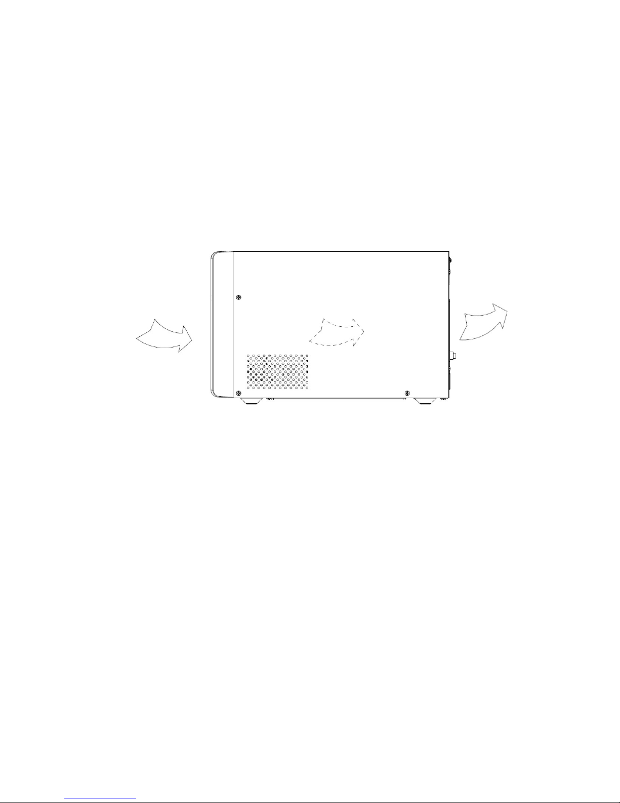
★ Do not block ventilation openings on the UPS’s housing. Ensure
the air vents on the front, side and rear of the UPS are not blocked.
Recommended at least 25cm of space on each side. The air flow
diagram is shown as below:
■ Figure 1.1 The Air Flow Diagram
★ UPS has provided earthed connector, in the final installed system
configuration, equipotential earth bonding to the external UPS
battery cabinets.
★ This UPS receives power from more than one
source-disconnection of AC source and the DC source is required
to de-energize this unit before servicing.
★ An additional circuit breaker or fuse with rating 32A and breaking
capacity 3kA shall be used between power source and input when
installation 3K/3K XL model.
★ An additional circuit breaker or fuse with rating 16A and breaking
capacity 3kA shall be used between power source and input when
installation 1K/1KXL/2K/2KXL model.
1.2 Operation
★ For safety consideration, do not disconnect the mains cable on the

-3-
UPS or the building wiring socket (grounded shockproof socket)
during operation, the grounding for the UPS and all loads
connected will be disconnected.
★ The UPS features its own, internal current source (batteries). You
may be electric shocked when you touch the UPS output sockets
or output terminal block even if the UPS is not connected to the
building wiring socket.
★ In order to fully disconnect the UPS, first press the OFF button to
turn off the UPS, and then disconnect the mains lead.
★ Ensure that no liquid or other external objects can enter the UPS.
★ Do not remove the enclosure. This system is to be serviced by
qualified service person only. There are NO USER SERVICEABLE
PARTS inside the UPS.
★ Remove the protective panel only after disconnecting the terminal
connections.
★ To connect external battery cabinets, use the expansion cable
suggested by the manufacturer in this manual.
★ Use No. 12 AWG (for 3K XL input/output wire), 90C copper wire
and 5kgf.cm Torque force when connecting to terminal block.
★ Please don’t disconnect battery connector when UPS work
normally (for 3K XL).
★ Before insert or pull out the battery connector (for 3K XL),the DC
breaker between UPS and external batteries must be cut off. And
do not handle the battery wire part while pulling out the battery
connector.
★ Danger - Risk of electrical shock, do not touch uninsulated battery
connector.
1.3 Maintenance, servicing and faults
★ The UPS operates with hazardous voltages. Repairs may be
carried out only by qualified maintenance/service person.
★ Caution - risk of electric shock. Even after the unit is disconnected

-4-
from the mains power supply (building wiring socket), components
inside the UPS are still connected to the battery which are
potentially dangerous.
★ Before carrying out any kind of service and/or maintenance,
disconnect the batteries. Verify that no current is present and no
hazardous voltage exists in the capacitor or BUS capacitor
terminals.
★ Batteries must be replaced only by qualified person.
★ Caution - risk of electric shock. The battery circuit is not isolated
from the input voltage. Hazardous voltages may occur between the
battery terminals and the ground. Verify that no voltage is present
before servicing!
★ Batteries have a high short-circuited current and pose a risk of
shock. Take all precautionary measures specified below and any
other measures necessary when working with batteries:
- remove all jewellery, wristwatches, rings and other metal objects
- use only tools with insulated grips and handles.
- Wear rubber gloves and boots.
- Do not lay tools or metal parts on top of batteries.
- Disconnect the charging source prior to connecting or
disconnecting battery terminals.
★ When changing batteries, replace with the same quantity and the
same type of batteries.
★ Do not attempt to dispose of batteries by burning them. It could
cause explosion.
★ Do not open or destroy batteries. Effluent electrolyte can cause
injury to the skin and eyes. It may be toxic.
★ Please replace the fuse only by a fuse of the same type and of the
same amperage in order to avoid fire hazards.
★ Do not dismantle the UPS, except the qualified maintenance
person.

-5-
1.4 Transport
★ Please transport the UPS only in the original packaging (to protect
against shock and impact).
1.5 Storage
★ The UPS must be stockpiled in the room where it is ventilated and
dry.
1.6 Standards
★ Safety
IEC/EN 62040-1
★ EMI
Conducted Emission..........................:IEC/EN 62040-2 Category C1
Radiated Emission.............................:IEC/EN 62040-2 Category C1
Harmonic Current...............................:IEC/EN 61000-3-2
Voltage Fluctuation and Flicker..........:IEC/EN 61000-3-3
★ EMS
ESD...................................................:IEC/EN 61000-4-2 Level 4
RS.....................................................:IEC/EN 61000-4-3 Level 3
EFT....................................................:IEC/EN 61000-4-4 Level 4
SURGE.............................................:IEC/EN 61000-4-5 Level 4
CS……………………………………...:IEC/EN 61000-4-6 Level 3
MS……………………………………..: IEC/EN 61000-4-8 Level 3
Voltaje Dips…………………………...: IEC/EN 61000-4-11
Low Frequency Signals.....................:IEC/EN 61000-2-2
* Safety
IS 16242(Part 1)/IEC/EN 62040-1
* EMC
IEC/EN 62040-2 (Only for 1K/2K/3K)

-6-
2. Description of Commonly Used Symbols
Some or all of the following symbols may be used in this manual. It is
advisable to familiarize yourself with them and understand their meaning:

-7-
3. Introduction
This On-Line-Series is an uninterruptible power supply incorporating
double-converter technology. It provides perfect protection specifically for
Linux, UNIX, and Windows servers.
The double-converter principle eliminates all mains power disturbances. A
rectifier converts the alternating current from the socket outlet to direct
current. This direct current charges the batteries and powers the inverter. On
the basis of this DC voltage, the inverter generates a sinusoidal AC voltage,
which permanently supplies the loads.
Computers and periphery are thus powered entirely by the mains voltage. In
the event of power failure, the maintenance-free batteries power the inverter.
This manual covers the UPS listed as follows. Please confirm whether it is
the model you intend to purchase by performing a visual inspection of the
Model No. on the rear panel of the UPS.
The Model List
Item Model name Power Rating
Model
type
Model
description
Other
1 9E-IN 1K
1000VA/
900W
Tower Standard model
Single Phase input
Single Phase
Output
2 9E-IN 2K
2000VA/
1800W
Tower Standard model
Single Phase input
Single Phase
Output
3 9E-IN 3K
3000VA/
2700W
Tower Standard model
Single Phase input
Single Phase
Output
4 9E-IN 1K XL
1000VA/
800W
Tower
Long Backup
time model
Single Phase input
Single Phase
Output
5 9E-IN 2K XL
2000VA/
1600W
Tower
Long Backup
time model
Single Phase input
Single Phase
Output
6 9E-IN 3K XL
3000VA/
2400W
Tower
Long Backup
time model
Single Phase input
Single Phase
Output
Note:The 1KXL, 2KXL , 3KXL with EBM connector models are long
backup time model.
-8-
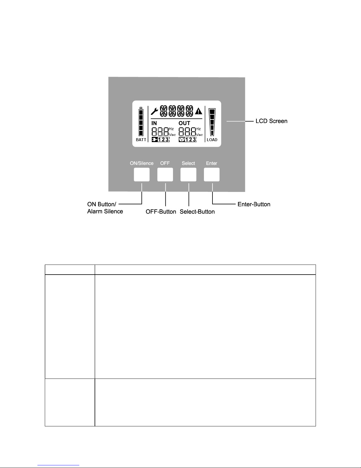
4. Panel Description
The display panel of 1K/1KXL/2K/2KXL/3K/3KXL is the same, which is
shown as below:
■ Figure 4.1 The Display Panel
4.1 Button
Switch Function
ON/Silence
Button
Turn on UPS system:
By pressing the ON-Button continuously for more than 1 second the
UPS system is turned on.
Deactivate acoustic alarm:
By pressing this Button, an acoustic alarm and LCD blue
background blinking can be deactivated in the battery mode.
By short touch this Button all acoustic alarms can be deactivated in
all modes.
Do the battery test:
By pressing this Button the UPS can do the battery test in the Line
mode or ECO mode or CVCF mode.
OFF
Button
When mains power is normal, the UPS system switches to No
output or Bypass mode by pressing OFF-Button, and the inverter is
off. At this moment, if Bypass is enabled, then the output sockets are
supplied with voltage via the bypass if the mains power is available.
Deactivate acoustic alarm:
-9-
By pressing this Button, an acoustic alarm and LCD blue
background blinking can be deactivated in the bypass mode.
Release the UPS from fault mode and EPO status.
Select
Button
The output voltage, frequency, Bypass disable/enable and operating
mode in No output or Bypass mode, External Battery Ah, Battery
remain time display disable/enable(only for 1K/2K/3K) and Charger
current in all mode, could be selected by pressing Select-Button,
and confirmed by pressing Enter-Button.
Enter
Button
Note: External Battery pack number cannot be select for Standard model (1K /2K
/3K ).
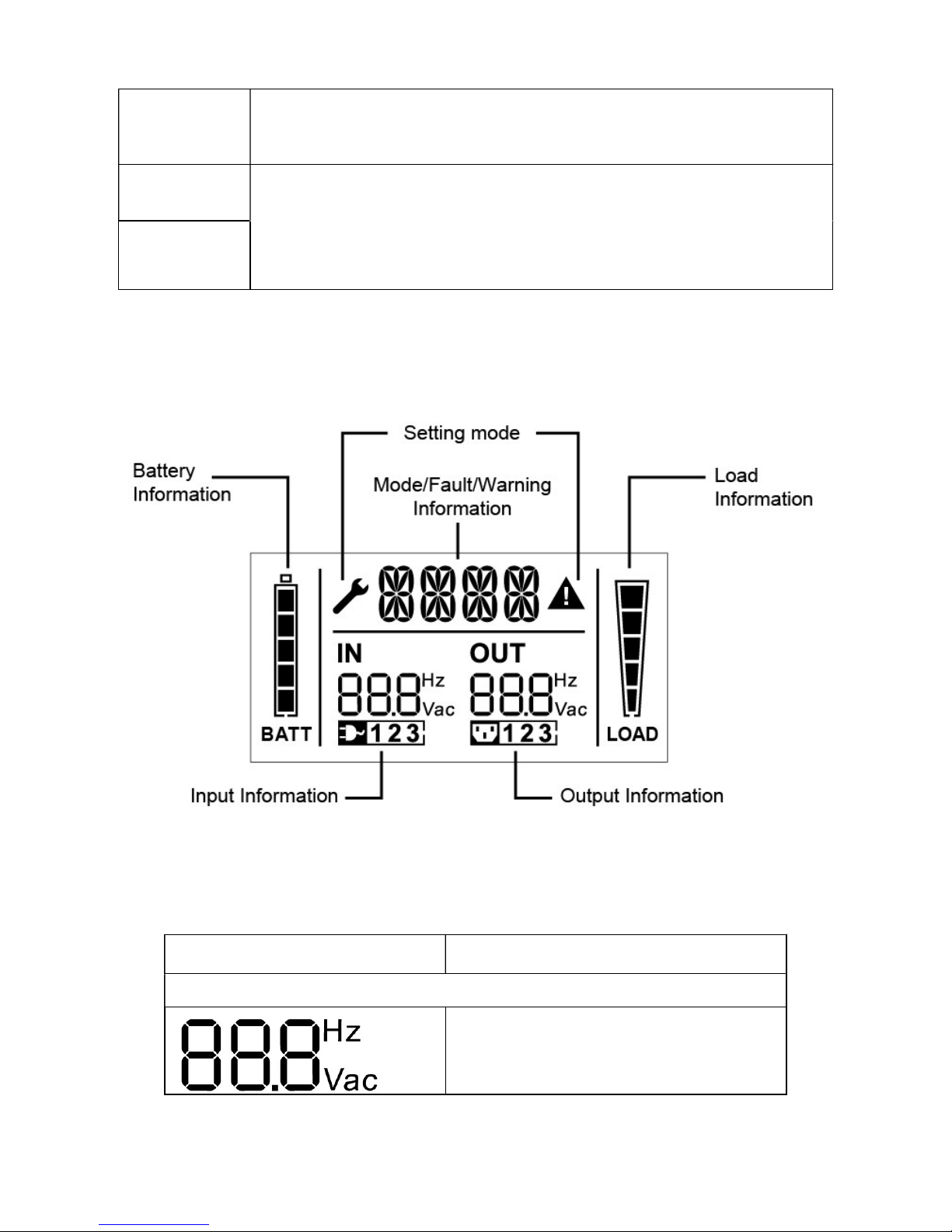
4.2 LCD description
■ Figure 4.2 The LCD Display
LCD icon Function
Display Function
Input Information
It indicates input voltage/frequency
value, which are displayed alternately.
-10-
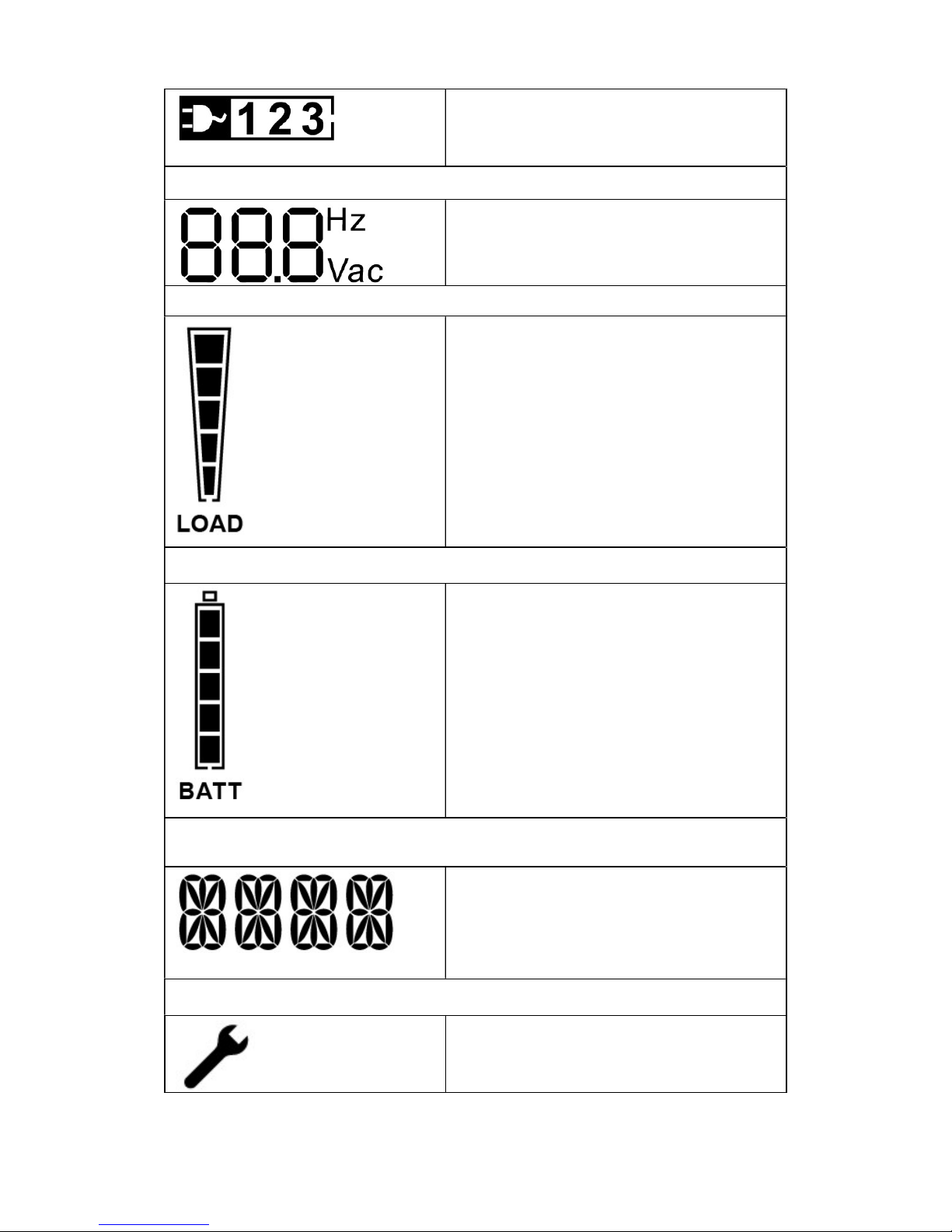
It indicates the input is connected with
mains, and the input power is single
phase input.
Output Information
It indicates output voltage/frequency
value, which are displayed alternately.
Load Information
It indicates the load level. Every grid
represents the level of 20%. The
lowest grid would be displayed if the
level is 5%~20%.
Battery Information
It indicates the battery capacity. Every
grid represents the capacity of 20%. If
the battery low alarm occurs, the
lowest grid will flash to remind you.
Mode/Fault/Warning Information
It Indicates the operating mode or
Fault kind or Warning kind or battery
remain time (only for 1K/2K/3K),
several warning kinds at the same time
could be displayed alternately.
Else
It indicates the UPS is in setting mode.

-11-
It indicates the UPS is in Fault mode or
has some warnings.
LCD idle function:
If you enable LCD background idle function, When UPS is off to standby
mode, LCD background will be turned off within 5 seconds. After any
key pressed, the LCD background will be lighted on.
 Loading...