

Eaton 9EEBM240, 9EEBM180, 9E20KiXL, 9E20Ki, 9E15Ki User Manual
...
powerquality.eaton.com
Eaton 9E
6-20kVA

CONTENT:
1. Introduction ............................................................................... 1
1.1 Safety instruction ............................................................... 1
1.2 Certification Standards ....................................................... 3
1.3 Special Symbols ................................................................ 4
2.Presentation ................................................................................ 5
2.1 Model List .......................................................................... 5
2.2 Electrical structure ............................................................. 5
2.3 UPS views ......................................................................... 7
3.Installation ................................................................................ 12
3.1 Unpacking ........................................................................ 12
3.2 Package content .............................................................. 13
3.3 Connection ...................................................................... 13
4.OPERATION .............................................................................. 24
4.1 Display and Buttons ......................................................... 24
4.2 Operating UPS ................................................................. 28
4.3 Configuration ................................................................... 30
4.4 Trouble shooting .............................................................. 32
4.5 Alarm codes ..................................................................... 34
5.Technical data .......................................................................... 35

1
1. Introduction
1.1 Safety instruction
The UPS must be installed and maintained exclusively by quailified
staff. See installation and operation instructions before connecting to
the supply.
The UPS must be installed with an earth connection. It has a high
leakage current. The first wire to be connected is the earth wire, which
must be connected to the terminal marked PE (yellow/green).
The UPS generates a leakage current of over 3.5 mA. The leakage
current of the load should be added to that of the UPS on the
protective earth wire.
The UPS needs a neutral connection to work properly. Operation
without Neutral may damage the unit.
A readily accessible disconnect device shall be incorporated in the
building installation wiring for permanently connected equipment.
The UPS generates hazardous electric voltages inside it even when
the input and/or battery switches are open. The inside of the UPS is
protected by safety guards that are not to be removed by non-qualified
staff. All installation and maintenance or other operations that entail
gaining access to the inside of the UPS require the use of tools and
are to be performed exclusively by qualified staff.
The UPS contains an energy source: the batteries. All terminals and
sockets may be powered even when the UPS is not connected to the
mains.
The total battery voltage is potentially hazardous: it may cause an
electric shock. The compartment containing the batteries is protected
by safety guards, which are not to be removed by non-qualified staff.

2
All battery installation and maintenance operations entail gaining
access to the inside of the UPS and require the use of tools: these
operations are to be performed exclusively by qualified staff.
The batteries replaced are to be considered as toxic waste and treated
accordingly. Dispose of used batteries according to the instructions.
Do not throw the batteries into fire: they could explode. Do not attempt
to open the battery casing: no maintenance work can be done on
them. In addition, the electrolyte is hazardous for the skin and eyes
and may be toxic.
Risk of explosion if battery is replaced by an incorrect type.
Do not turn on the UPS if you see any leaks of liquid or a white
powder residue.
Make sure that no water, liquid in general and/or other foreign matter
gets inside the UPS.
Under hazardous conditions, turn off the UPS at the “1/0” main power
switch and open all the isolators present (see the user manual to
locate the “1/0” main power switch and the isolators).
Do not open the battery fuse holders while the UPS is powering the
load from the batteries. An interruption of the battery DC voltage may
cause an electric arc and result in breakage of the equipment and/or
fire.
The energy required to power the load is provided by the batteries in
the event of a power failure. if the battery protection were open, the
load would be powered off.
Fuses have to be replaced with the same type if necessary.
To connect external battery cabinets, use the expansion cable
suggested by the manufacturer in this manual.

3
1.2 Certification Standards
Safety
IEC 62040-1:2008
IEC 60950-1:2005 (Modified)
EMC
Conducted Emission: IEC 62040-2. Category C3
Radiated Emission: IEC 62040-2. Category C3
ESD:IEC 61000-4-2. Contact: Level 2, Air discharge: Level 3
RS:IEC 61000-4-3. Level 3
EFT:IEC/EN 61000-4-4. Level 4
Surge:IEC/EN 61000-4-5. Level 4
CS:IEC/EN 61000-4-6. Level 3
MS:IEC/EN 61000-4-8. Level 3
Voltage Dips, short interruptions and voltage variations:IEC/EN 61000-4-11
Warning: This is a product for commercial and industrial application, in other
environment installation restrictions or additional measures may be needed to
prevent disturbances. Additional curbs may be needed while output wiring
length is more than 10m or communication wiring length is more than 3m.
4
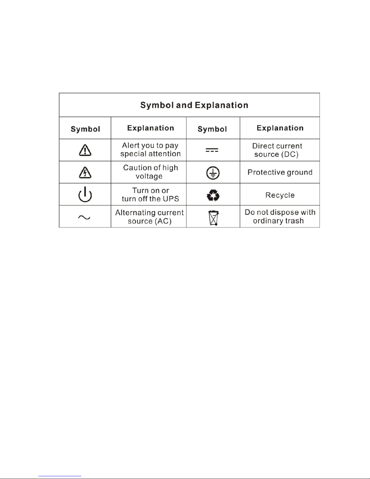
1.3 Special Symbols
The following are examples of symbols used on the UPS or accessories to
show you the important information:
5
2.Presentation
9E series UPS uses ON-LINE double conversion technology, resulting in
the highest levels of reliability and maximum protection for critical loads.
2.1 Model List
Model
Power Ratings
PF
Voltage (Output)
9E6Ki
6kVA/4.8kW
0.8
230V (220/240)
9E10Ki
10kVA/8kW Combo
0.8
230V (220/240)
9E10KiXL
10kVA/8kW Combo
0.8
230V (220/240)
9E15Ki
15kVA/12kW Combo
0.8
230V (220/240)
9E20Ki
20kVA/16kW Combo
0.8
230V (220/240)
9E20KiXL
20kVA/16kW Combo
0.8
230V (220/240)
9EEBM180
For 9E6Ki
180V
9EEBM240
For 9E10Ki, 9E10KiXL
240V
“XL” Model: Model with internal supercharger, and without internal
batteries. Other models with internal batteries
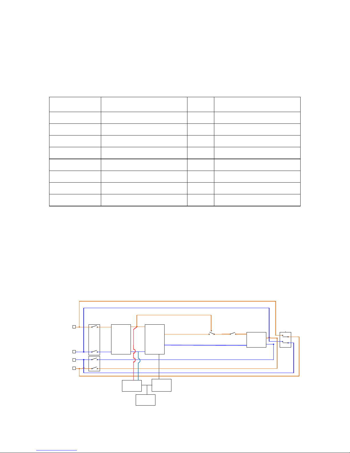
2.2 Electrical structure
9E6Ki
INPUT
OUTPUT
N
L
N
L1
Input
filter
AC/DC—DC/AC
Output
filter
Internal
power
Charger
Battery
Input
Switch
Bypass
Maintain Switch
`
Output
Switch
Main power wiring
6
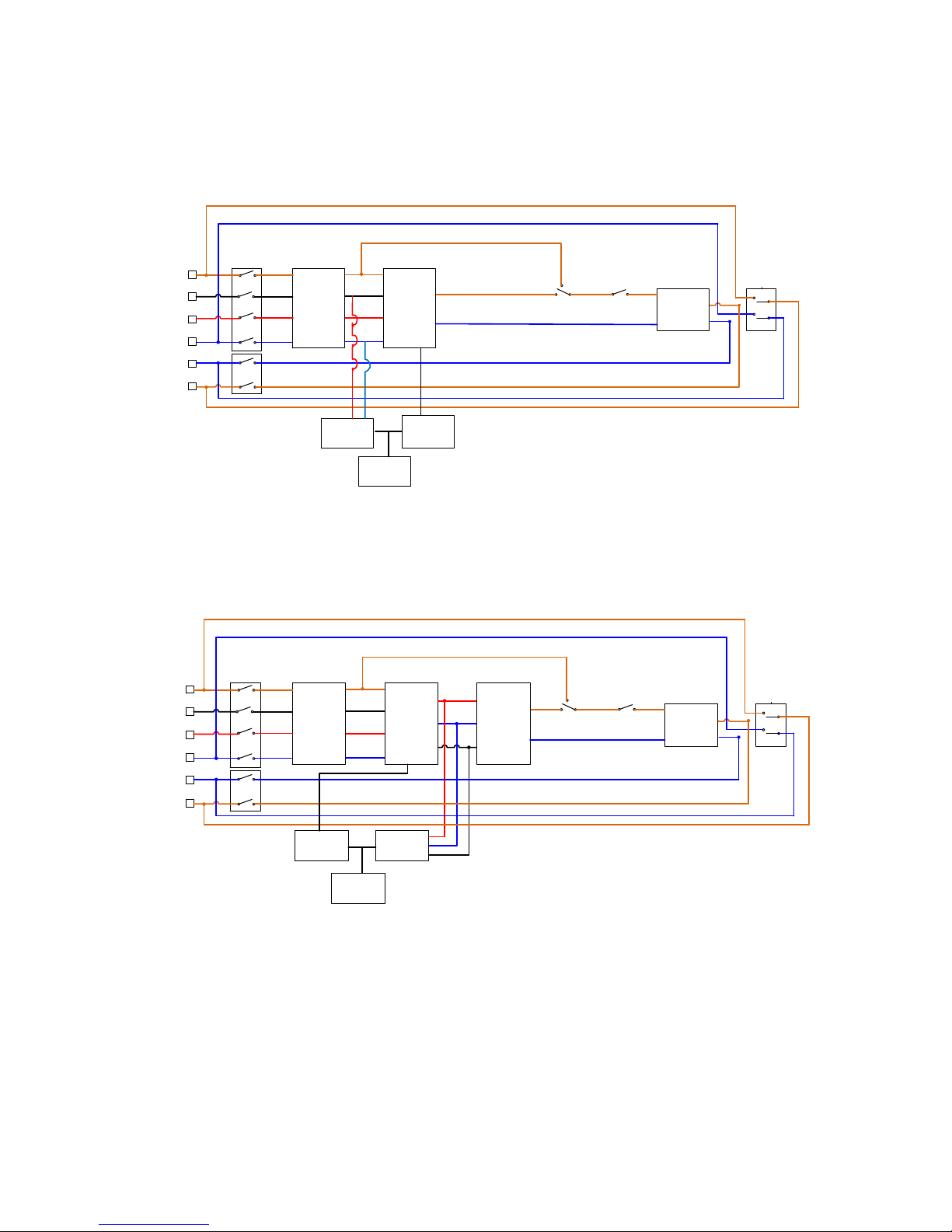
9E10Ki, 9E10KiXL
INPUT
OUTPUT
N
L
N
L2
L1
L3
Input
filter
AC/DC—DC/AC
Output
filter
Internal
power
Charger
Battery
Input
Switch
Bypass
Maintain Switch
`
Output
Switch
Main power wiring
9E15Ki, 9E20Ki, 9E20KiXL
INPUT
OUTPUT
N
L
N
L2
L1
L3
Input
filter
AC-DC DC-AC
Output
filter
Internal
power
Charger
Battery
Input
Switch
Bypass
Maintain Switch
`
Output
Switch
Main power wiring
7
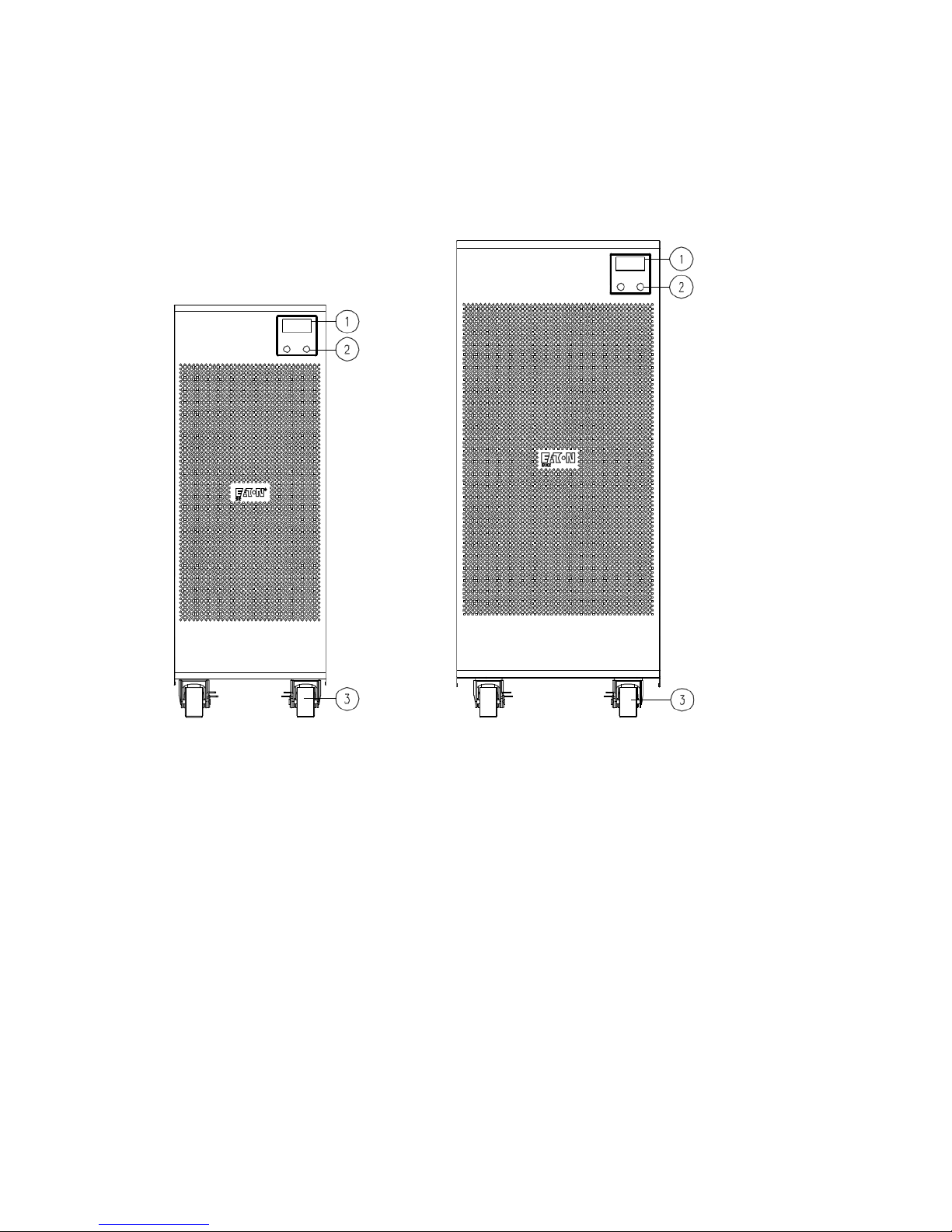
2.3 UPS views
2.3.1 UPS Front view
①
Display
②
Multipurpose buttons
③
Wheels (front wheels swivel and can be locked, fixed rear wheels)
8
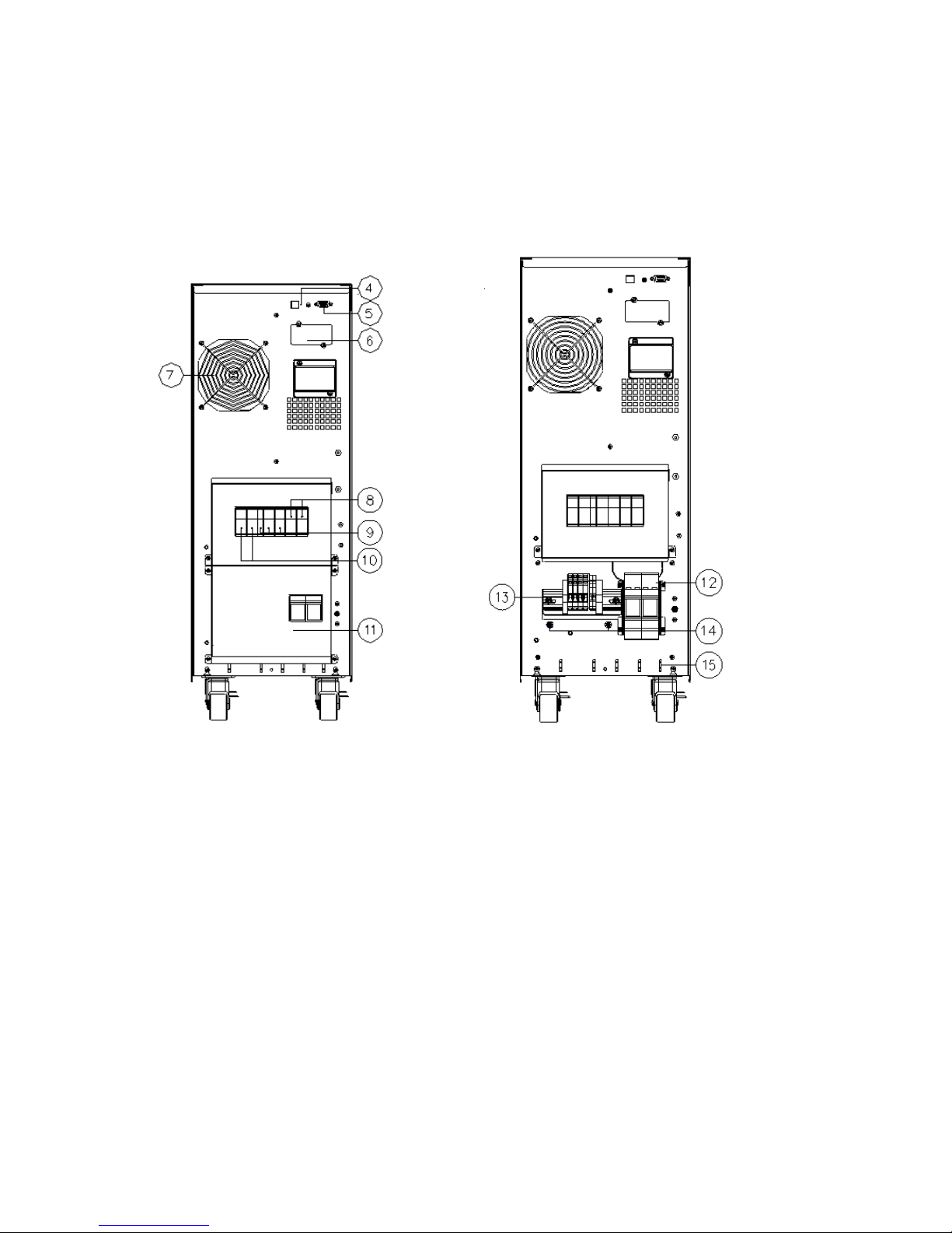
2.3.2 UPS Rear view
9E6Ki
With backpanel cover
9E6Ki
Without backpanel cover
④
USB communication port
⑩
Input switch
⑤
RS232 communication
port
⑪
Cover for terminals
⑥
Slot for optional
communication card
⑫
Fuse
⑦
Cooling fan(s)
⑬
Terminals for I/O cable connection
(refer to related section)
⑧
Output switch
⑭
Earthing screws
⑨
Manual bypass for
maintenance
⑮
Tie wrap hold-down
9E10Ki/9E10KiXL
With backpanel cover
9E10Ki/9E10KiXL
Without backpanel cover
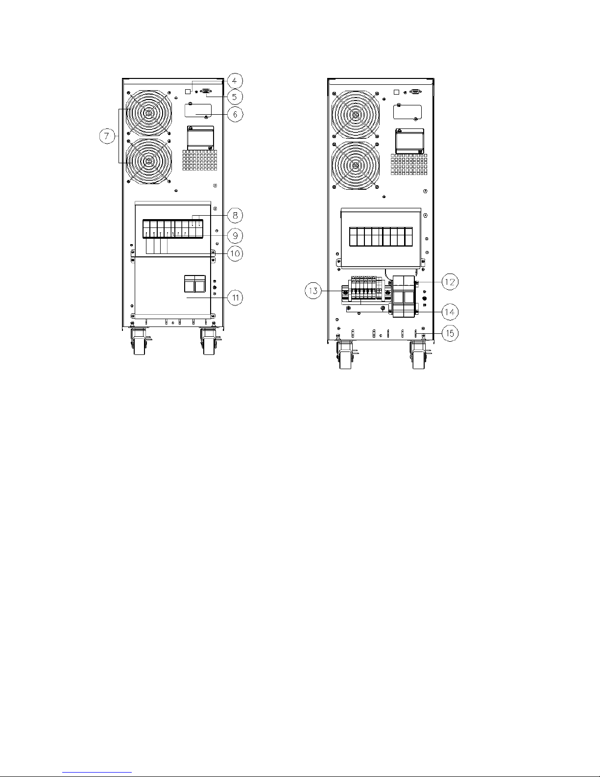
9
④
USB communication port
⑩
Input switch
⑤
RS232 communication
port
⑪
Cover for terminals
⑥
Slot for optional
communication card
⑫
Fuse
⑦
Cooling fan(s)
⑬
Terminals for I/O cable connection
(refer to related section)
⑧
Output switch
⑭
Earthing screws
⑨
Manual bypass for
maintenance
⑮
Tie wrap hold-down

10
UPS Rear view
9E15Ki/9E15KiXL/9E20Ki/9E20KiXL
With backpanel cover
9E15Ki/9E15KiXL/9E20Ki/9E20KiXL
Without backpanel cover
④
RS232 communication port
⑩
Input switch
⑤
USB communication port
⑪
Cover for terminals
⑥
Slot for optional
communication card
⑫
Terminals for I/O cable connection
(refer to related section)
⑦
Cooling fans
⑬
Earthing screws
⑧
Output switch
⑭
Fuse
⑨
Manual bypass for
maintenance
⑮
Tie wrap hold-down
 Loading...