

Eaton 9E Installation And Operation Manual

Eaton® 9E UPS
40–60 kVA (208/220V)
Installation and Operation Manual


Eaton® 9E UPS
40–60 kVA (208/220V)
Installation and Operation Manual

IMPORTANT SAFETY INSTRUCTIONS SAVE THESE INSTRUCTIONS
This manual contains important instructions that you should follow during installation and
CONSIGNES DE SÉCURITÉ IMPORTANTES CONSERVER CES INSTRUCTIONS
maintenance of the UPS and batteries. Please read all instructions before operating the equipment
and save this manual for future reference.
Ce manuel comporte des instructions importantes que vous êtes invité à suivre lors de toute
procédure d'installation et de maintenance des batteries et de l'onduleur. Veuillez consulter
entièrement ces instructions avant de faire fonctionner l'équipement et conserver ce manuel afin
de pouvoir vous y reporter ultérieurement.
Eaton, Powerware, and Mini-Slot are registered trademarks and ConnectUPS is a trademark of Eaton
Corporation or its subsidiaries and affiliates. Modbus is a registered trademark of Schneider Electric. National
Electrical Code and NEC are registered trademarks of National Fire Protection Association, Inc. All other
trademarks are property of their respective companies.
©Copyright 2011–2012 Eaton Corporation, Raleigh, NC, USA. All rights reserved. No part of this document may
be reproduced in any way without the express written approval of Eaton Corporation.

Table of Contents
1 INTRODUCTION . . . . . . . . . . . . . . . . . . . . . . . . . . . . . . . . . . . . . . . . . . . . . . . . . . . . . . . . . . . . . . . . . . . . . . . . . . . . . . . . . . . . . . 1-1
1.1 UPS Standard Features . . . . . . . . . . . . . . . . . . . . . . . . . . . . . . . . . . . . . . . . . . . . . . . . . . . . . . . . . . . . . . . . . 1-2
1.1.1 Installation Features. . . . . . . . . . . . . . . . . . . . . . . . . . . . . . . . . . . . . . . . . . . . . . . . . . . . . . . . . . . . . . . 1-2
1.1.2 Control Panel . . . . . . . . . . . . . . . . . . . . . . . . . . . . . . . . . . . . . . . . . . . . . . . . . . . . . . . . . . . . . . . . . . . . 1-2
1.1.3 Customer Interface . . . . . . . . . . . . . . . . . . . . . . . . . . . . . . . . . . . . . . . . . . . . . . . . . . . . . . . . . . . . . . . 1-2
1.1.4 High-Efficiency Normal Mode . . . . . . . . . . . . . . . . . . . . . . . . . . . . . . . . . . . . . . . . . . . . . . . . . . . . . . . 1-2
1.1.5 Advanced Battery Management . . . . . . . . . . . . . . . . . . . . . . . . . . . . . . . . . . . . . . . . . . . . . . . . . . . . . 1-2
1.2 Options and Accessories. . . . . . . . . . . . . . . . . . . . . . . . . . . . . . . . . . . . . . . . . . . . . . . . . . . . . . . . . . . . . . . . 1-2
1.2.1 External Battery Cabinet . . . . . . . . . . . . . . . . . . . . . . . . . . . . . . . . . . . . . . . . . . . . . . . . . . . . . . . . . . . 1-2
1.2.2 Integrated Accessory Cabinet-Distribution . . . . . . . . . . . . . . . . . . . . . . . . . . . . . . . . . . . . . . . . . . . . . 1-2
1.2.3 Integrated Transformer Cabinet. . . . . . . . . . . . . . . . . . . . . . . . . . . . . . . . . . . . . . . . . . . . . . . . . . . . . . 1-3
1.2.4 Integrated Accessory Cabinet-Bypass . . . . . . . . . . . . . . . . . . . . . . . . . . . . . . . . . . . . . . . . . . . . . . . . . 1-3
1.2.5 Integrated Accessory Cabinet-Tie . . . . . . . . . . . . . . . . . . . . . . . . . . . . . . . . . . . . . . . . . . . . . . . . . . . . 1-3
1.2.6 Integrated Accessory Cabinet-Tie and Bypass . . . . . . . . . . . . . . . . . . . . . . . . . . . . . . . . . . . . . . . . . . 1-3
1.2.7 Parallel System . . . . . . . . . . . . . . . . . . . . . . . . . . . . . . . . . . . . . . . . . . . . . . . . . . . . . . . . . . . . . . . . . . 1-3
1.2.8 Reduced Battery String Model . . . . . . . . . . . . . . . . . . . . . . . . . . . . . . . . . . . . . . . . . . . . . . . . . . . . . . 1-3
1.2.9 Monitoring and Communication . . . . . . . . . . . . . . . . . . . . . . . . . . . . . . . . . . . . . . . . . . . . . . . . . . . . . 1-4
1.2.10 Dual Feed. . . . . . . . . . . . . . . . . . . . . . . . . . . . . . . . . . . . . . . . . . . . . . . . . . . . . . . . . . . . . . . . . . . . . . . 1-4
1.2.11 Maintenance Bypass . . . . . . . . . . . . . . . . . . . . . . . . . . . . . . . . . . . . . . . . . . . . . . . . . . . . . . . . . . . . . . 1-4
1.3 Battery System . . . . . . . . . . . . . . . . . . . . . . . . . . . . . . . . . . . . . . . . . . . . . . . . . . . . . . . . . . . . . . . . . . . . . . . 1-4
1.4 Basic System Configurations. . . . . . . . . . . . . . . . . . . . . . . . . . . . . . . . . . . . . . . . . . . . . . . . . . . . . . . . . . . . . 1-4
1.5 Using This Manual. . . . . . . . . . . . . . . . . . . . . . . . . . . . . . . . . . . . . . . . . . . . . . . . . . . . . . . . . . . . . . . . . . . . . 1-4
1.6 Conventions Used in This Manual. . . . . . . . . . . . . . . . . . . . . . . . . . . . . . . . . . . . . . . . . . . . . . . . . . . . . . . . . 1-5
1.7 Symbols, Controls, and Indicators. . . . . . . . . . . . . . . . . . . . . . . . . . . . . . . . . . . . . . . . . . . . . . . . . . . . . . . . . 1-5
1.8 For More Information . . . . . . . . . . . . . . . . . . . . . . . . . . . . . . . . . . . . . . . . . . . . . . . . . . . . . . . . . . . . . . . . . . 1-6
1.9 Getting Help . . . . . . . . . . . . . . . . . . . . . . . . . . . . . . . . . . . . . . . . . . . . . . . . . . . . . . . . . . . . . . . . . . . . . . . . . 1-6
2 SAFETY WARNINGS . . . . . . . . . . . . . . . . . . . . . . . . . . . . . . . . . . . . . . . . . . . . . . . . . . . . . . . . . . . . . . . . . . . . . . . . . . . . . . . . . . 2-1
SECTION 1 — INSTALLATION
3 UPS INSTALLATION PLAN AND UNPACKING . . . . . . . . . . . . . . . . . . . . . . . . . . . . . . . . . . . . . . . . . . . . . . . . . . . . . . . . . . . . 3-1
3.1 Creating an Installation Plan . . . . . . . . . . . . . . . . . . . . . . . . . . . . . . . . . . . . . . . . . . . . . . . . . . . . . . . . . . . . . 3-1
3.2 Preparing the Site . . . . . . . . . . . . . . . . . . . . . . . . . . . . . . . . . . . . . . . . . . . . . . . . . . . . . . . . . . . . . . . . . . . . . 3-1
3.2.1 Environmental and Installation Considerations . . . . . . . . . . . . . . . . . . . . . . . . . . . . . . . . . . . . . . . . . . 3-1
3.2.2 UPS System Power Wiring Preparation. . . . . . . . . . . . . . . . . . . . . . . . . . . . . . . . . . . . . . . . . . . . . . . . 3-6
3.2.3 UPS System Interface Wiring Preparation. . . . . . . . . . . . . . . . . . . . . . . . . . . . . . . . . . . . . . . . . . . . . . 3-10
3.3 Battery Type . . . . . . . . . . . . . . . . . . . . . . . . . . . . . . . . . . . . . . . . . . . . . . . . . . . . . . . . . . . . . . . . . . . . . . . . . 3-11
3.4 Inspecting and Unpacking the UPS Cabinets . . . . . . . . . . . . . . . . . . . . . . . . . . . . . . . . . . . . . . . . . . . . . . . . 3-11
4 UPS SYSTEM INSTALLATION . . . . . . . . . . . . . . . . . . . . . . . . . . . . . . . . . . . . . . . . . . . . . . . . . . . . . . . . . . . . . . . . . . . . . . . . . . 4-1
4.1 Preliminary Installation Information . . . . . . . . . . . . . . . . . . . . . . . . . . . . . . . . . . . . . . . . . . . . . . . . . . . . . . . . 4-1
4.2 Unloading the UPS Cabinet from the Pallet. . . . . . . . . . . . . . . . . . . . . . . . . . . . . . . . . . . . . . . . . . . . . . . . . . 4-1
4.3 Installing Power Terminal Cover Base. . . . . . . . . . . . . . . . . . . . . . . . . . . . . . . . . . . . . . . . . . . . . . . . . . . . . . 4-6
4.4 External Battery Cabinet Installation . . . . . . . . . . . . . . . . . . . . . . . . . . . . . . . . . . . . . . . . . . . . . . . . . . . . . . . 4-7
4.5 Integrated Transformer Cabinet Installation . . . . . . . . . . . . . . . . . . . . . . . . . . . . . . . . . . . . . . . . . . . . . . . . . 4-7
4.6 Integrated Accessory Cabinet-Bypass Installation. . . . . . . . . . . . . . . . . . . . . . . . . . . . . . . . . . . . . . . . . . . . . 4-8
Eaton 9E UPS (40–60 kVA, 208/220V) Installation and Operation Manual P-164000058—Rev 4 www.eaton.com/powerquality i

Table of Contents
4.7 Integrated Accessory Cabinet-Tie . . . . . . . . . . . . . . . . . . . . . . . . . . . . . . . . . . . . . . . . . . . . . . . . . . . . . . . . . . 4-8
4.8 Integrated Accessory Cabinet-Tie and Bypass . . . . . . . . . . . . . . . . . . . . . . . . . . . . . . . . . . . . . . . . . . . . . . . . 4-8
4.9 Integrated Accessory Cabinet-Distribution . . . . . . . . . . . . . . . . . . . . . . . . . . . . . . . . . . . . . . . . . . . . . . . . . . . 4-8
4.10 External Power Wiring Installation . . . . . . . . . . . . . . . . . . . . . . . . . . . . . . . . . . . . . . . . . . . . . . . . . . . . . . . . . 4-8
4.11 Installing Interface Connections . . . . . . . . . . . . . . . . . . . . . . . . . . . . . . . . . . . . . . . . . . . . . . . . . . . . . . . . . . . 4-13
4.11.1 Installing Building Alarm Connections . . . . . . . . . . . . . . . . . . . . . . . . . . . . . . . . . . . . . . . . . . . . . . . . . . 4-13
4.11.2 Installing Parallel Pull Chain and CAN Control Wiring and Connections . . . . . . . . . . . . . . . . . . . . . . . . 4-18
4.11.3 Installing Mini-Slot Interface Connections . . . . . . . . . . . . . . . . . . . . . . . . . . . . . . . . . . . . . . . . . . . . . . . 4-19
4.12 Installing a REPO Switch. . . . . . . . . . . . . . . . . . . . . . . . . . . . . . . . . . . . . . . . . . . . . . . . . . . . . . . . . . . . . . . . . 4-21
4.13 Connecting Internal Battery Strings . . . . . . . . . . . . . . . . . . . . . . . . . . . . . . . . . . . . . . . . . . . . . . . . . . . . . . . . 4-24
4.14 Initial Startup . . . . . . . . . . . . . . . . . . . . . . . . . . . . . . . . . . . . . . . . . . . . . . . . . . . . . . . . . . . . . . . . . . . . . . . . . . 4-27
4.15 Completing the Installation Checklist . . . . . . . . . . . . . . . . . . . . . . . . . . . . . . . . . . . . . . . . . . . . . . . . . . . . . . . 4-27
SECTION 2 — OPERATION
5 UNDERSTANDING UPS OPERATION . . . . . . . . . . . . . . . . . . . . . . . . . . . . . . . . . . . . . . . . . . . . . . . . . . . . . . . . . . . . . . . . . . . . 5-1
5.1 UPS System Overview . . . . . . . . . . . . . . . . . . . . . . . . . . . . . . . . . . . . . . . . . . . . . . . . . . . . . . . . . . . . . . . . . . 5-1
5.2 Single UPS . . . . . . . . . . . . . . . . . . . . . . . . . . . . . . . . . . . . . . . . . . . . . . . . . . . . . . . . . . . . . . . . . . . . . . . . . . . 5-2
5.2.1 Modes . . . . . . . . . . . . . . . . . . . . . . . . . . . . . . . . . . . . . . . . . . . . . . . . . . . . . . . . . . . . . . . . . . . . . . . . . . 5-2
5.2.2 High-Efficiency Normal Mode . . . . . . . . . . . . . . . . . . . . . . . . . . . . . . . . . . . . . . . . . . . . . . . . . . . . . . . . 5-2
5.2.3 Standard Normal Mode . . . . . . . . . . . . . . . . . . . . . . . . . . . . . . . . . . . . . . . . . . . . . . . . . . . . . . . . . . . . . 5-2
5.2.4 Bypass Mode . . . . . . . . . . . . . . . . . . . . . . . . . . . . . . . . . . . . . . . . . . . . . . . . . . . . . . . . . . . . . . . . . . . . 5-4
5.2.5 Battery Mode . . . . . . . . . . . . . . . . . . . . . . . . . . . . . . . . . . . . . . . . . . . . . . . . . . . . . . . . . . . . . . . . . . . . 5-5
5.3 Single UPS Unit System Oneline Configurations . . . . . . . . . . . . . . . . . . . . . . . . . . . . . . . . . . . . . . . . . . . . . . 5-6
6 UPS OPERATING INSTRUCTIONS . . . . . . . . . . . . . . . . . . . . . . . . . . . . . . . . . . . . . . . . . . . . . . . . . . . . . . . . . . . . . . . . . . . . . . . 6-1
6.1 UPS Controls and Indicators . . . . . . . . . . . . . . . . . . . . . . . . . . . . . . . . . . . . . . . . . . . . . . . . . . . . . . . . . . . . . . 6-1
6.1.1 Control Panel . . . . . . . . . . . . . . . . . . . . . . . . . . . . . . . . . . . . . . . . . . . . . . . . . . . . . . . . . . . . . . . . . . . . . 6-2
6.1.2 Circuit Breakers . . . . . . . . . . . . . . . . . . . . . . . . . . . . . . . . . . . . . . . . . . . . . . . . . . . . . . . . . . . . . . . . . . . 6-2
6.2 Using the Control Panel . . . . . . . . . . . . . . . . . . . . . . . . . . . . . . . . . . . . . . . . . . . . . . . . . . . . . . . . . . . . . . . . . 6-3
6.2.1 Status Indicators . . . . . . . . . . . . . . . . . . . . . . . . . . . . . . . . . . . . . . . . . . . . . . . . . . . . . . . . . . . . . . . . . . 6-3
6.2.2 System Events . . . . . . . . . . . . . . . . . . . . . . . . . . . . . . . . . . . . . . . . . . . . . . . . . . . . . . . . . . . . . . . . . . . 6-4
6.2.3 Using the LCD and Pushbuttons . . . . . . . . . . . . . . . . . . . . . . . . . . . . . . . . . . . . . . . . . . . . . . . . . . . . . . 6-5
6.2.4 Using the Menu. . . . . . . . . . . . . . . . . . . . . . . . . . . . . . . . . . . . . . . . . . . . . . . . . . . . . . . . . . . . . . . . . . . 6-6
6.2.5 Mimic Screen . . . . . . . . . . . . . . . . . . . . . . . . . . . . . . . . . . . . . . . . . . . . . . . . . . . . . . . . . . . . . . . . . . . . 6-6
6.2.6 Display Menu Operation . . . . . . . . . . . . . . . . . . . . . . . . . . . . . . . . . . . . . . . . . . . . . . . . . . . . . . . . . . . . 6-7
6.2.7 System Controls . . . . . . . . . . . . . . . . . . . . . . . . . . . . . . . . . . . . . . . . . . . . . . . . . . . . . . . . . . . . . . . . . . 6-9
6.3 Single UPS Operation . . . . . . . . . . . . . . . . . . . . . . . . . . . . . . . . . . . . . . . . . . . . . . . . . . . . . . . . . . . . . . . . . . . 6-11
6.3.1 Starting the UPS in High-Efficiency Normal Mode (Default Mode) . . . . . . . . . . . . . . . . . . . . . . . . . . . . 6-11
6.3.2 Starting the UPS in Bypass Mode. . . . . . . . . . . . . . . . . . . . . . . . . . . . . . . . . . . . . . . . . . . . . . . . . . . . . 6-12
6.3.3 Transfer from Normal to Bypass Mode. . . . . . . . . . . . . . . . . . . . . . . . . . . . . . . . . . . . . . . . . . . . . . . . . 6-13
6.3.4 Transfer from Bypass to Normal Mode. . . . . . . . . . . . . . . . . . . . . . . . . . . . . . . . . . . . . . . . . . . . . . . . . 6-13
6.3.5 Transfer from HE Normal Mode to Standard Normal Mode . . . . . . . . . . . . . . . . . . . . . . . . . . . . . . . . . 6-14
6.3.6 Transfer from Standard Normal Mode to HE Normal mode . . . . . . . . . . . . . . . . . . . . . . . . . . . . . . . . . 6-14
6.3.7 Transfer from Normal Mode to Maintenance Bypass . . . . . . . . . . . . . . . . . . . . . . . . . . . . . . . . . . . . . . 6-14
6.3.8 Transfer from Maintenance Bypass to Normal Mode . . . . . . . . . . . . . . . . . . . . . . . . . . . . . . . . . . . . . . 6-14
6.3.9 UPS and Critical Load Shutdown. . . . . . . . . . . . . . . . . . . . . . . . . . . . . . . . . . . . . . . . . . . . . . . . . . . . . . 6-15
6.3.10 Charger Control . . . . . . . . . . . . . . . . . . . . . . . . . . . . . . . . . . . . . . . . . . . . . . . . . . . . . . . . . . . . . . . . . . . 6-16
6.3.11 Battery Test. . . . . . . . . . . . . . . . . . . . . . . . . . . . . . . . . . . . . . . . . . . . . . . . . . . . . . . . . . . . . . . . . . . . . . 6-16
ii Eaton 9E UPS (40–60 kVA, 208/220V) Installation and Operation Manual P-164000058—Rev 4 www.eaton.com/powerquality

Table of Contents
6.3.12 Using the UPS LOAD OFF Command . . . . . . . . . . . . . . . . . . . . . . . . . . . . . . . . . . . . . . . . . . . . . . . . . 6-16
6.3.13 Using the Remote Emergency Power-off Switch . . . . . . . . . . . . . . . . . . . . . . . . . . . . . . . . . . . . . . . . 6-17
6.4 Multiple UPS Parallel Operation . . . . . . . . . . . . . . . . . . . . . . . . . . . . . . . . . . . . . . . . . . . . . . . . . . . . . . . . . . 6-19
6.4.1 Starting the Parallel UPS in High-Efficiency Normal Mode (Default Mode) . . . . . . . . . . . . . . . . . . . . . 6-19
6.4.2 Starting the Parallel UPS in Bypass Mode. . . . . . . . . . . . . . . . . . . . . . . . . . . . . . . . . . . . . . . . . . . . . . 6-20
6.4.3 Transfer from Normal to Bypass Mode . . . . . . . . . . . . . . . . . . . . . . . . . . . . . . . . . . . . . . . . . . . . . . . . 6-21
6.4.4 Transfer from Bypass to Normal Mode . . . . . . . . . . . . . . . . . . . . . . . . . . . . . . . . . . . . . . . . . . . . . . . . 6-21
6.4.5 Transfer from HE Normal Mode to Standard Normal Mode . . . . . . . . . . . . . . . . . . . . . . . . . . . . . . . . 6-21
6.4.6 Transfer from Standard Normal Mode to HE Normal mode . . . . . . . . . . . . . . . . . . . . . . . . . . . . . . . . 6-22
6.4.7 Transfer from Normal Mode to Maintenance Bypass . . . . . . . . . . . . . . . . . . . . . . . . . . . . . . . . . . . . . 6-22
6.4.8 Transfer from Maintenance Bypass to Normal Mode . . . . . . . . . . . . . . . . . . . . . . . . . . . . . . . . . . . . . 6-22
6.4.9 Single UPS Shutdown . . . . . . . . . . . . . . . . . . . . . . . . . . . . . . . . . . . . . . . . . . . . . . . . . . . . . . . . . . . . . 6-22
6.4.10 Single UPS Restart . . . . . . . . . . . . . . . . . . . . . . . . . . . . . . . . . . . . . . . . . . . . . . . . . . . . . . . . . . . . . . . 6-23
6.4.11 UPS and Critical Load Shutdown . . . . . . . . . . . . . . . . . . . . . . . . . . . . . . . . . . . . . . . . . . . . . . . . . . . . . 6-23
6.4.12 Charger Control . . . . . . . . . . . . . . . . . . . . . . . . . . . . . . . . . . . . . . . . . . . . . . . . . . . . . . . . . . . . . . . . . . 6-24
6.4.13 Battery Test . . . . . . . . . . . . . . . . . . . . . . . . . . . . . . . . . . . . . . . . . . . . . . . . . . . . . . . . . . . . . . . . . . . . . 6-24
6.4.14 Using the UPS LOAD OFF Command . . . . . . . . . . . . . . . . . . . . . . . . . . . . . . . . . . . . . . . . . . . . . . . . . 6-25
6.4.15 Using the Remote Emergency Power-off Switch . . . . . . . . . . . . . . . . . . . . . . . . . . . . . . . . . . . . . . . . 6-26
7 COMMUNICATION . . . . . . . . . . . . . . . . . . . . . . . . . . . . . . . . . . . . . . . . . . . . . . . . . . . . . . . . . . . . . . . . . . . . . . . . . . . . . . . . . . . 7-1
7.1 Mini-Slot Cards . . . . . . . . . . . . . . . . . . . . . . . . . . . . . . . . . . . . . . . . . . . . . . . . . . . . . . . . . . . . . . . . . . . . . . . 7-1
7.2 Building Alarm Monitoring. . . . . . . . . . . . . . . . . . . . . . . . . . . . . . . . . . . . . . . . . . . . . . . . . . . . . . . . . . . . . . . 7-1
8 UPS MAINTENANCE . . . . . . . . . . . . . . . . . . . . . . . . . . . . . . . . . . . . . . . . . . . . . . . . . . . . . . . . . . . . . . . . . . . . . . . . . . . . . . . . . . 8-1
8.1 Important Safety Instructions . . . . . . . . . . . . . . . . . . . . . . . . . . . . . . . . . . . . . . . . . . . . . . . . . . . . . . . . . . . . 8-1
8.2 Performing Preventive Maintenance. . . . . . . . . . . . . . . . . . . . . . . . . . . . . . . . . . . . . . . . . . . . . . . . . . . . . . . 8-2
8.2.1 DAILY Maintenance. . . . . . . . . . . . . . . . . . . . . . . . . . . . . . . . . . . . . . . . . . . . . . . . . . . . . . . . . . . . . . . 8-2
8.2.2 MONTHLY Maintenance . . . . . . . . . . . . . . . . . . . . . . . . . . . . . . . . . . . . . . . . . . . . . . . . . . . . . . . . . . . 8-2
8.2.3 ANNUAL Maintenance . . . . . . . . . . . . . . . . . . . . . . . . . . . . . . . . . . . . . . . . . . . . . . . . . . . . . . . . . . . . 8-3
8.2.4 BATTERY Maintenance . . . . . . . . . . . . . . . . . . . . . . . . . . . . . . . . . . . . . . . . . . . . . . . . . . . . . . . . . . . . 8-3
8.3 Installing Batteries. . . . . . . . . . . . . . . . . . . . . . . . . . . . . . . . . . . . . . . . . . . . . . . . . . . . . . . . . . . . . . . . . . . . . 8-4
8.4 Recycling the Used Battery or UPS. . . . . . . . . . . . . . . . . . . . . . . . . . . . . . . . . . . . . . . . . . . . . . . . . . . . . . . . 8-4
8.5 Maintenance Training . . . . . . . . . . . . . . . . . . . . . . . . . . . . . . . . . . . . . . . . . . . . . . . . . . . . . . . . . . . . . . . . . . 8-4
9 PRODUCT SPECIFICATIONS . . . . . . . . . . . . . . . . . . . . . . . . . . . . . . . . . . . . . . . . . . . . . . . . . . . . . . . . . . . . . . . . . . . . . . . . . . . 9-1
9.1 Model Numbers . . . . . . . . . . . . . . . . . . . . . . . . . . . . . . . . . . . . . . . . . . . . . . . . . . . . . . . . . . . . . . . . . . . . . . 9-1
9.2 Specifications . . . . . . . . . . . . . . . . . . . . . . . . . . . . . . . . . . . . . . . . . . . . . . . . . . . . . . . . . . . . . . . . . . . . . . . . 9-1
9.2.1 UPS Input. . . . . . . . . . . . . . . . . . . . . . . . . . . . . . . . . . . . . . . . . . . . . . . . . . . . . . . . . . . . . . . . . . . . . . . 9-1
9.2.2 UPS Output . . . . . . . . . . . . . . . . . . . . . . . . . . . . . . . . . . . . . . . . . . . . . . . . . . . . . . . . . . . . . . . . . . . . . 9-2
9.2.3 UPS Environmental . . . . . . . . . . . . . . . . . . . . . . . . . . . . . . . . . . . . . . . . . . . . . . . . . . . . . . . . . . . . . . . 9-2
9.2.4 Battery Runtimes (in Minutes) at Full load. . . . . . . . . . . . . . . . . . . . . . . . . . . . . . . . . . . . . . . . . . . . . . 9-2
WARRANTY. . . . . . . . . . . . . . . . . . . . . . . . . . . . . . . . . . . . . . . . . . . . . . . . . . . . . . . . . . . . . . . . . . . . . . . . . . . . . . . . . . . . . . . . . . . . . . . . W-1
Eaton 9E UPS (40–60 kVA, 208/220V) Installation and Operation Manual P-164000058—Rev 4 www.eaton.com/powerquality iii

Table of Contents
This page intentionally left blank.
iv Eaton 9E UPS (40–60 kVA, 208/220V) Installation and Operation Manual P-164000058—Rev 4 www.eaton.com/powerquality

List of Figures
Figure 1-1. Eaton 9E UPS (40–60 kVA) . . . . . . . . . . . . . . . . . . . . . . . . . . . . . . . . . . . . . . . . . . . . . . . . . . . . . . . . . . . . . . 1-1
Figure 3-1. UPS Cabinet Dimensions (Front and Right Side Views) . . . . . . . . . . . . . . . . . . . . . . . . . . . . . . . . . . . . . . . . 3-3
Figure 3-2. UPS Cabinet Dimensions (Top and Bottom Views). . . . . . . . . . . . . . . . . . . . . . . . . . . . . . . . . . . . . . . . . . . . 3-4
Figure 3-3. UPS Cabinet Center of Gravity . . . . . . . . . . . . . . . . . . . . . . . . . . . . . . . . . . . . . . . . . . . . . . . . . . . . . . . . . . . 3-5
Figure 3-4. Remote EPO Switch Dimensions . . . . . . . . . . . . . . . . . . . . . . . . . . . . . . . . . . . . . . . . . . . . . . . . . . . . . . . . . 3-6
Figure 3-5. UPS Cabinet as Shipped on Pallet (wood container removed) . . . . . . . . . . . . . . . . . . . . . . . . . . . . . . . . . . . 3-13
Figure 4-1. Removing the Front Shipping Bracket. . . . . . . . . . . . . . . . . . . . . . . . . . . . . . . . . . . . . . . . . . . . . . . . . . . . . . 4-2
Figure 4-2. Attaching the Ramp to the Pallet. . . . . . . . . . . . . . . . . . . . . . . . . . . . . . . . . . . . . . . . . . . . . . . . . . . . . . . . . . 4-3
Figure 4-3. Removing the Rear Shipping Bracket . . . . . . . . . . . . . . . . . . . . . . . . . . . . . . . . . . . . . . . . . . . . . . . . . . . . . . 4-4
Figure 4-4. Rolling the Cabinet Down the Ramp . . . . . . . . . . . . . . . . . . . . . . . . . . . . . . . . . . . . . . . . . . . . . . . . . . . . . . . 4-5
Figure 4-5. UPS Power Terminal Cover Parts . . . . . . . . . . . . . . . . . . . . . . . . . . . . . . . . . . . . . . . . . . . . . . . . . . . . . . . . . 4-6
Figure 4-6. UPS Power Terminal Cover Base Installation and Conduit Landing Wire Entry Locations . . . . . . . . . . . . . . 4-7
Figure 4-7. Power Terminal Locations. . . . . . . . . . . . . . . . . . . . . . . . . . . . . . . . . . . . . . . . . . . . . . . . . . . . . . . . . . . . . . . 4-10
Figure 4-8. Power Terminal Detail . . . . . . . . . . . . . . . . . . . . . . . . . . . . . . . . . . . . . . . . . . . . . . . . . . . . . . . . . . . . . . . . . . 4-11
Figure 4-9. Power Terminal Cover Top Installation . . . . . . . . . . . . . . . . . . . . . . . . . . . . . . . . . . . . . . . . . . . . . . . . . . . . . 4-12
Figure 4-10. Interface Terminal Locations . . . . . . . . . . . . . . . . . . . . . . . . . . . . . . . . . . . . . . . . . . . . . . . . . . . . . . . . . . . . . 4-13
Figure 4-11. Interface Terminal Detail (Terminal Cover Removed) . . . . . . . . . . . . . . . . . . . . . . . . . . . . . . . . . . . . . . . . . . 4-14
Figure 4-12. Building Alarm Terminal Block Connector Assignments . . . . . . . . . . . . . . . . . . . . . . . . . . . . . . . . . . . . . . . . 4-14
Figure 4-13. Interface Terminal Cover . . . . . . . . . . . . . . . . . . . . . . . . . . . . . . . . . . . . . . . . . . . . . . . . . . . . . . . . . . . . . . . . 4-16
Figure 4-14. Interface Conduit Landing and Wiring Channel . . . . . . . . . . . . . . . . . . . . . . . . . . . . . . . . . . . . . . . . . . . . . . . 4-17
Figure 4-15. Interface Wiring Access . . . . . . . . . . . . . . . . . . . . . . . . . . . . . . . . . . . . . . . . . . . . . . . . . . . . . . . . . . . . . . . . 4-17
Figure 4-16. Pull Chain Terminal Block Connector Assignments. . . . . . . . . . . . . . . . . . . . . . . . . . . . . . . . . . . . . . . . . . . . 4-18
Figure 4-18. REPO Switch . . . . . . . . . . . . . . . . . . . . . . . . . . . . . . . . . . . . . . . . . . . . . . . . . . . . . . . . . . . . . . . . . . . . . . . . . 4-21
Figure 4-19. REPO Terminal Block Connector Assignments. . . . . . . . . . . . . . . . . . . . . . . . . . . . . . . . . . . . . . . . . . . . . . . 4-22
Figure 4-20. Normally-Open REPO Switch Wiring. . . . . . . . . . . . . . . . . . . . . . . . . . . . . . . . . . . . . . . . . . . . . . . . . . . . . . . 4-23
Figure 4-21. Normally-Closed REPO Switch Wiring . . . . . . . . . . . . . . . . . . . . . . . . . . . . . . . . . . . . . . . . . . . . . . . . . . . . . 4-24
Figure 4-22. Battery Location . . . . . . . . . . . . . . . . . . . . . . . . . . . . . . . . . . . . . . . . . . . . . . . . . . . . . . . . . . . . . . . . . . . . . . 4-25
Figure 4-23. Battery Section . . . . . . . . . . . . . . . . . . . . . . . . . . . . . . . . . . . . . . . . . . . . . . . . . . . . . . . . . . . . . . . . . . . . . . . 4-26
Figure 4-24. Battery String Connections . . . . . . . . . . . . . . . . . . . . . . . . . . . . . . . . . . . . . . . . . . . . . . . . . . . . . . . . . . . . . . 4-27
Figure 5-1. Main Elements of the UPS System. . . . . . . . . . . . . . . . . . . . . . . . . . . . . . . . . . . . . . . . . . . . . . . . . . . . . . . . 5-1
Figure 5-2. Path of Current Through the UPS in standard Normal Mode . . . . . . . . . . . . . . . . . . . . . . . . . . . . . . . . . . . . 5-3
Figure 5-3. Path of Current Through the UPS in Bypass Mode. . . . . . . . . . . . . . . . . . . . . . . . . . . . . . . . . . . . . . . . . . . . 5-4
Figure 5-4. Path of Current Through the UPS in Battery Mode . . . . . . . . . . . . . . . . . . . . . . . . . . . . . . . . . . . . . . . . . . . . 5-5
Figure 5-5. UPS System Oneline – Internal Battery. . . . . . . . . . . . . . . . . . . . . . . . . . . . . . . . . . . . . . . . . . . . . . . . . . . . . 5-7
Figure 5-6. UPS System Oneline – External Battery . . . . . . . . . . . . . . . . . . . . . . . . . . . . . . . . . . . . . . . . . . . . . . . . . . . . 5-8
Figure 6-1. UPS Controls and Indicators . . . . . . . . . . . . . . . . . . . . . . . . . . . . . . . . . . . . . . . . . . . . . . . . . . . . . . . . . . . . . 6-1
Figure 6-2. UPS Breakers . . . . . . . . . . . . . . . . . . . . . . . . . . . . . . . . . . . . . . . . . . . . . . . . . . . .
Figure 6-3. UPS Control Panel . . . . . . . . . . . . . . . . . . . . . . . . . . . . . . . . . . . . . . . . . . . . . . . . . . . . . . . . . . . . . . . . . . . . . 6-3
Figure 6-8. Maintenance Bypass Interlock Cover . . . . . . . . . . . . . . . . . . . . . . . . . . . . . . . . . . . . . . . . . . . . . . . . . . . . . . 6-15
Figure 6-9. REPO Operation . . . . . . . . . . . . . . . . . . . . . . . . . . . . . . . . . . . . . . . . . . . . . . . . . . . . . . . . . . . . . . . . . . . . . . 6-18
Figure 7-1. Optional Mini-Slot Cards . . . . . . . . . . . . . . . . . . . . . . . . . . . . . . . . . . . . . . . . . . . . . . . . . . . . . . . . . . . . . . . . 7-1
Figure 8-1. Air Filter Location . . . . . . . . . . . . . . . . . . . . . . . . . . . . . . . . . . . . . . . . . . . . . . . . . . . . . . . . . . . . . . . . . . . . . 8-3
. . . . . . . . . . . . . . . . . . . . 6-2
Eaton 9E UPS (40–60 kVA, 208/220V) Installation and Operation Manual P-164000058—Rev 4 www.eaton.com/powerquality v

List of Figures
This page intentionally left blank.
vi Eaton 9E UPS (40–60 kVA, 208/220V) Installation and Operation Manual P-164000058—Rev 4 www.eaton.com/powerquality

List of Tables
Table 3-1. UPS Cabinet Weights . . . . . . . . . . . . . . . . . . . . . . . . . . . . . . . . . . . . . . . . . . . . . . . . . . . . . . . . . . . . . . . . . . 3-2
Table 3-2. UPS Cabinet Clearances . . . . . . . . . . . . . . . . . . . . . . . . . . . . . . . . . . . . . . . . . . . . . . . . . . . . . . . . . . . . . . . . 3-2
Table 3-3. Air Conditioning or Ventilation Requirements During Full Load Operation . . . . . . . . . . . . . . . . . . . . . . . . . . 3-2
Table 3-4. Input/Output Ratings and External Wiring Requirements for the Eaton 9E-40, 9E–60/40, and 9E–60/60. . . 3-7
Table 3-5. UPS External Power Cable Terminations for the Eaton 9E-40, 9E–60/40, and 9E–60/60 . . . . . . . . . . . . . . . 3-8
Table 3-6. Power Cable Conduit Requirements . . . . . . . . . . . . . . . . . . . . . . . . . . . . . . . . . . . . . . . . . . . . . . . . . . . . . . . 3-9
Table 3-7. Recommended Input Circuit Breaker Ratings . . . . . . . . . . . . . . . . . . . . . . . . . . . . . . . . . . . . . . . . . . . . . . . . 3-9
Table 3-8. Recommended Bypass and Output Circuit Breaker Ratings. . . . . . . . . . . . . . . . . . . . . . . . . . . . . . . . . . . . . 3-10
Table 3-9. Battery Type . . . . . . . . . . . . . . . . . . . . . . . . . . . . . . . . . . . . . . . . . . . . . . . . . . . . . . . . . . . . . . . . . . . . . . . . . 3-11
Table 4-1. Building Alarm Connections . . . . . . . . . . . . . . . . . . . . . . . . . . . . . . . . . . . . . . . . . . . . . . . . . . . . . . . . . . . . . 4-14
Table 4-2. Pull Chain Connections . . . . . . . . . . . . . . . . . . . . . . . . . . . . . . . . . . . . . . . . . . . . . . . . . . . . . . . . . . . . . . . . . 4-18
Table 4-3. REPO Connections . . . . . . . . . . . . . . . . . . . . . . . . . . . . . . . . . . . . . . . . . . . . . . . . . . . . . . . . . . . . . . . . . . . . 4-22
Table 4-4. Normally-Open REPO Wire Terminations . . . . . . . . . . . . . . . . . . . . . . . . . . . . . . . . . . . . . . . . . . . . . . . . . . . 4-23
Table 4-5. Normally-Closed REPO Wire Terminations . . . . . . . . . . . . . . . . . . . . . . . . . . . . . . . . . . . . . . . . . . . . . . . . . . 4-23
Table 6-1. Status Indicators . . . . . . . . . . . . . . . . . . . . . . . . . . . . . . . . . . . . . . . . . . . . . . . . . . . . . . . . . . . . . . . . . . . . . . 6-3
Table 6-2. Display Function Menu Map . . . . . . . . . . . . . . . . . . . . . . . . . . . . . . . . . . . . . . . . . . . . . . . . . . . . . . . . . . . . . 6-6
Table 6-3. Display Menu Operation . . . . . . . . . . . . . . . . . . . . . . . . . . . . . . . . . . . . . . . . . . . . . . . . . . . . . . . . . . . . . . . . 6-7
Table 6-4. Command Menu Operation. . . . . . . . . . . . . . . . . . . . . . . . . . . . . . . . . . . . . . . . . . . . . . . . . . . . . . . . . . . . . . 6-10
Table 6-5. Typical System Status Messages . . . . . . . . . . . . . . . . . . . . . . . . . . . . . . . . . . . . . . . . . . . . . . . . . . . . . . . . . 6-10
Eaton 9E UPS (40–60 kVA, 208/220V) Installation and Operation Manual P-164000058—Rev 4 www.eaton.com/powerquality vii

List of Tables
This page intentionally left blank.
viii Eaton 9E UPS (40–60 kVA, 208/220V) Installation and Operation Manual P-164000058—Rev 4 www.eaton.com/powerquality
Chapter 1 Introduction
The Eaton®9E 40–60 kVA uninterruptible power supply (UPS) is a true online, continuous-duty,
transformerless, double-conversion, solid-state, three-phase system, providing conditioned and uninterruptible
AC power to protect the customer's load from power failures.
The Eaton 9E 40–60 kVA online power protection system is used to prevent loss of valuable electronic
information, minimize equipment downtime, and minimize the adverse effect on production equipment due to
unexpected power problems.
The Eaton 9E 40–60 kVA UPS continually monitors incoming electrical power and removes the surges, spikes,
sags, and other irregularities that are inherent in commercial utility power. Working with a building's electrical
system, the UPS system supplies clean, consistent power that sensitive electronic equipment requires for
reliable operation. During brownouts, blackouts, and other power interruptions, batteries provide emergency
power to safeguard operation.
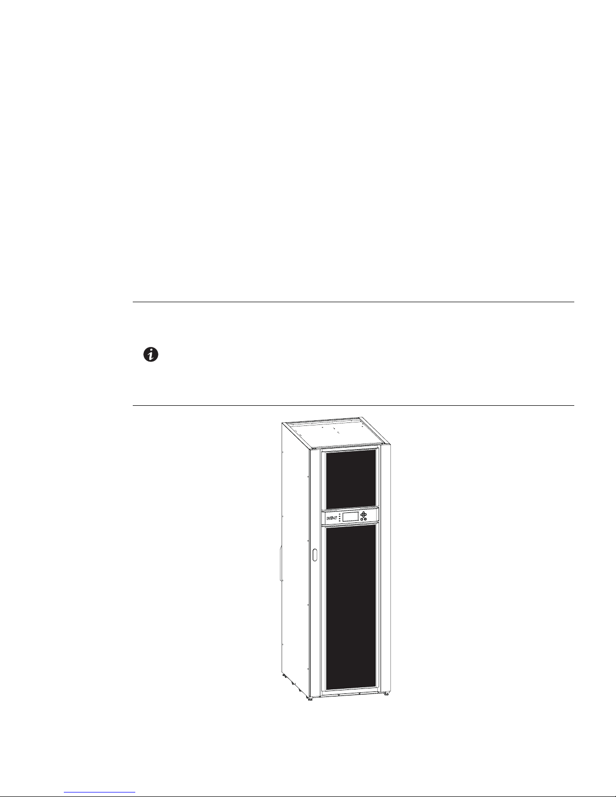
The UPS is housed in a single free-standing cabinet, with safety shields behind the door for hazardous voltage
protection. Figure 1-1 shows the Eaton 9E 40–60 kVA UPS.
NOTE 1 Startup may be performed by the customer’s battery qualified electrical contractor
NOTE 2 Startup and operational checks for parallel systems or installations with accessory
for single (not parallel) UPS installations without any accessory cabinets such as an
External Battery Cabinet.
cabinets must be performed by an authorized Eaton Customer Service Engineer, or
the warranty terms specified on page W-1 become void. This service is offered as
part of the sales contract for the UPS. Contact an Eaton service representative in
advance (usually a two-week notice is required) to reserve a preferred startup date.
Figure 1-1. Eaton 9E UPS (40–60 kVA)
Eaton 9E UPS (40–60 kVA, 208/220V) Installation and Operation Manual P-164000058—Rev 4 www.eaton.com/powerquality 1-1

Introduction
1.1 UPS Standard Features
The UPS has many standard features that provide cost-effective and consistently reliable power protection. The
descriptions in this section provide a brief overview of the UPS standard features.
1.1.1 Installation Features
Power wiring can be routed to the back of the cabinet with connections made to easily accessible terminals.
Control wiring is routed through the top of the cabinet and must be installed in accordance with Class 1 wiring
methods.
1.1.2 Control Panel
The control panel, located on the front of the UPS, contains a liquid crystal display (LCD) and pushbutton
switches to control the operation of the UPS and to display the status of the UPS system. See Chapter 6, “UPS
Operating Instructions,” for additional information.
1.1.3 Customer Interface
l
Building Alarm Monitoring – Up to three inputs in the UPS are available to connect the facility's alarm
system contacts. Some system configurations may limit the number of inputs available. The UPS uses
these inputs to monitor the building alarms in addition to the UPS status. See Chapter 7, “Communication,”
for additional information.
l
Mini-Slot Communication Bays – Two communication bays are standard equipment. One to two optional
Mini-Slot
installed at the rear of the UPS and are hot-pluggable. See Chapter 7, “Communication,” for additional
information.
®
connectivity cards can be installed in the UPS module at any time. Mini-Slot cards are quickly
1.1.4 High-Efficiency Normal Mode
The 9E Series UPS offers a High-Efficiency (HE) normal mode with double-conversion on demand that allows
the UPS to operate in standby bypass mode. This mode allows the 9E UPS to achieve 98% efficiency while
still protecting the load. High-efficiency mode is the default normal operating mode. See Chapter 6, “UPS
Operating Instructions,” for additional information.
1.1.5 Advanced Battery Management
A three-stage charging system increases battery service life by optimizing recharge time, and protects batteries
from damage due to high current charging and inverter ripple currents. Charging at high currents can overheat
and damage batteries.
1.2 Options and Accessories
Contact an Eaton sales representative for information about the following options.
1.2.1 External Battery Cabinet
Battery backup protection with additional runtime can be provide by equipping the UPS system with up to two
External Battery Cabinets (EBCs) containing sealed lead-acid, maintenance-free batteries. The EBCs are
available with two or three battery strings. The EBCs are housed in single, free-standing cabinets designed for
line-up-and-match installation, but may be installed separate from the UPS cabinet. The recommended
installation location for adjacent battery cabinets is on the right side of the UPS cabinet.
1.2.2 Integrated Accessory Cabinet-Distribution
The Integrated Accessory Cabinet-Distribution (IAC-D) provides power distribution with a 42-pole distribution
panel and up to three optional 3-pole 125A subfeed breakers. The IAC-D is housed in a single, free-standing
cabinet designed for line-up-and-match installation, but may be installed separate from the UPS cabinet. The
recommended installation location for an adjacent IAC-D is to the left of the UPS cabinet.
1-2 Eaton 9E UPS (40–60 kVA, 208/220V) Installation and Operation Manual P-164000058—Rev 4 www.eaton.com/powerquality

Introduction
1.2.3 Integrated Transformer Cabinet
An single transformer Integrated Transformer Cabinet (ITC) provides three-phase 480 Vac input to three-phase
208Y/120 Vac output voltage transformation and isolation for input to the Eaton 9E UPS. An optional Dual
transformer ITC adds three-phase 208 Vac input to three-phase 480Y/277 Vac output voltage transformation
and isolation for output to the critical load. The ITC is housed in a single, free-standing cabinet designed for
line-up-and-match installation, but may be installed separate from the UPS cabinet. The recommended
installation location for an adjacent ITC is to the left of the UPS cabinet.
1.2.4 Integrated Accessory Cabinet-Bypass
An Integrated Accessory Cabinet-Bypass (IAC-B) provides maintenance bypass functions. The IAC-B is
available in a three breaker configuration enabling power to completely bypass the UPS. The UPS can then be
safely serviced or replaced without interrupting power to critical systems. A four breaker configuration is
available to provide a convenient method for removing power from the UPS when using the maintenance
bypass to supply the load. The IAC-B is housed in a single, free-standing cabinet designed for line-up-and-match
installation, but may be installed separate from the UPS cabinet. The recommended installation location for an
adjacent IAC-B is to the left of the UPS cabinet.
1.2.5 Integrated Accessory Cabinet-Tie
An Integrated Accessory Cabinet-Tie (IAC-T) provides the ability to parallel up to four UPSs together for
increased capacity and/or redundant capability. The IAC-T is housed in a single, free-standing cabinet designed
for line-up-and-match installation, but may be installed separate from the UPS cabinet. The recommended
installation location for an adjacent IAC-T is to the left of the UPS cabinet.
1.2.6 Integrated Accessory Cabinet-Tie and Bypass
An Integrated Accessory Cabinet-Tie and Bypass (IAC-TB) provides the ability to parallel two UPSs together for
increased capacity and/or redundant capability. In addition, maintenance bypass functions enable power to
completely bypass the UPS power module. The IAC-T is housed in a single, free-standing cabinet designed for
line-up-and-match installation, but may be installed separate from the UPS cabinet. The recommended
installation location for an adjacent IAC-T is to the left of the UPS cabinet.
1.2.7 Parallel System
NOTE All UPSs in a parallel system must have the same battery configuration.
A parallel UPS system with up to four UPSs can be installed to provide a parallel capacity and/or redundant
system. This load sharing system provides more capacity than a single UPS, and can provide backup,
depending on the load and configuration. In addition, when one UPS is taken out of service for maintenance or
is not operating properly, a redundant UPS continues to supply uninterrupted power to the critical load. A
Controller Area Network (CAN) provides connectivity for system metering and operational mode control. The
parallel system consists of two to four UPSs each with a parallel CAN, and either a IAC-T or IAC-TB to act as a
tie point and to control the output.
1.2.8 Reduced Battery String Model
The Eaton 9E-40 model is configured with six battery strings instead of eight to optimize the run time for 40 kVA
with a subsequent reduction in cost and weight. If increased battery run time is required in the future, an
upgrade kit is available to increase the internal battery system to eight strings, converting the Eaton 9E-40 to a
Eaton 9E–60/40. After the upgrade kit is installed, the Eaton 9E–60/40 is also upgradable to a Eaton 9E–60/60
with a firmware upgrade installed by an authorized Eaton Customer Service Engineer.
Eaton 9E UPS (40–60 kVA, 208/220V) Installation and Operation Manual P-164000058—Rev 4 www.eaton.com/powerquality 1-3

Introduction
1.2.9 Monitoring and Communication
Mini-Slot Cards – Optional Mini-Slot® cards support several protocols, such as SNMP, HTTP, Modbus® and
RS232.
See Chapter 7, “Communication,“ for additional information on monitoring and communication features.
1.2.10 Dual Feed
Optional dual-feed input terminals are available to provide a separate bypass feed to the UPS.
1.2.11 Maintenance Bypass
The optional internal Maintenance Bypass consists of a Bypass circuit breaker used to control the AC input to
the UPS bypass, an output breaker controlling the inverter output, and a Maintenance Bypass breaker used to
partially isolate the UPS so that a limited number of components can be serviced without interrupting power
to critical systems.
1.3 Battery System
The battery system is internal to the UPS cabinet or can be an external cabinet. Internal and external batteries
can not be used at the same time. All UPSs in a parallel system must have the same battery configuration. The
battery system provides emergency short-term backup power to safeguard operation during brownouts,
blackouts, and other power interruptions. The battery system is equipped with lead-acid batteries.
1.4 Basic System Configurations
The following basic UPS system configurations are possible:
l
Single UPS with internal batteries
l
Single UPS with one or two external battery cabinets
l
Single UPS with internal batteries and accessory cabinets
l
Single UPS with one or two external battery cabinets and accessory cabinets
The UPS system configuration can be enhanced by adding optional accessories such as a Remote Emergency
Power-off (REPO) control or Mini-Slot communication cards.
1.5 Using This Manual
This manual describes how to install and operate the Eaton 9E 40–60 kVA. Read and understand the procedures
described in this manual to ensure trouble-free installation and operation. In particular, be thoroughly familiar
with the REPO procedure (see paragraph 6.3.13).
The information in this manual is divided into sections and chapters. The system, options, and accessories
being installed dictate which parts of this manual should be read. At a minimum, Chapters 1 through 4
and Chapter 6 should be examined.
Read through each procedure before beginning the procedure. Perform only those procedures that apply to the
UPS system being installed or operated.
1-4 Eaton 9E UPS (40–60 kVA, 208/220V) Installation and Operation Manual P-164000058—Rev 4 www.eaton.com/powerquality
1.6 Conventions Used in This Manual
This manual uses these type conventions:
l
Bold type highlights important concepts in discussions, key terms in procedures, and menu options, or
represents a command or option that you type or enter at a prompt.
l
Italic type highlights notes and new terms where they are defined.
l
Screen type represents information that appears on the screen or LCD.
Icon Description
Note Information notes call attention to important features or instructions.
[Keys] Brackets are used when referring to a specific key, such as [Enter] or [Ctrl].
In this manual, the term UPS refers only to the UPS cabinet and its internal elements. The term UPS system
refers to the entire power protection system – the UPS cabinet, an external battery system, and options or
accessories installed.
1.7 Symbols, Controls, and Indicators
The following are examples of symbols used on the UPS or accessories to alert you to important information:
Introduction
RISK OF ELECTRIC SHOCK - Observe the warning associated with the risk
of electric shock symbol.
CAUTION: REFER TO OPERATOR'S MANUAL - Refer to your operator's
manual for additional information, such as important operating and
maintenance instructions.
This symbol indicates that you should not discard the UPS or the UPS
batteries in the trash. This product contains sealed, lead-acid batteries and
must be disposed of properly. For more information, contact your local
recycling/reuse or hazardous waste center.
This symbol indicates that you should not discard waste electrical or
electronic equipment (WEEE) in the trash. For proper disposal, contact your
local recycling/reuse or hazardous waste center.
Eaton 9E UPS (40–60 kVA, 208/220V) Installation and Operation Manual P-164000058—Rev 4 www.eaton.com/powerquality 1-5

Introduction
1.8 For More Information
Refer to the Eaton 9E External Battery Cabinet Installation Manual for the following additional information:
l
Installation instructions, including site preparation, planning for installation, wiring and safety information,
and detailed illustrations of cabinets with dimensional and connection point drawings
Refer to the Eaton 9E Integrated Accessory Cabinet-Distribution Installation and Operation Manual for the
following additional information:
l
Installation instructions, including site preparation, planning for installation, wiring and safety information,
and detailed illustrations of cabinets with dimensional and connection point drawings
l
Operation, including breakers, standard features and optional accessories, procedures for using the tie and
bypass functions, and information about maintenance
Refer to the Eaton 9E Integrated Transformer Cabinet Installation Manual for the following additional
information:
l
Installation instructions, including site preparation, planning for installation, wiring and safety information,
and detailed illustrations of cabinets with dimensional and connection point drawings
Refer to the Eaton 9E Integrated Accessory Cabinet-Tie and Bypass Installation and Operation Manual for the
following additional information:
l
Installation instructions, including site preparation, planning for installation, wiring and safety information,
and detailed illustrations of cabinets with dimensional and connection point drawings
l
Operation, including breakers, standard features and optional accessories, procedures for using the tie and
bypass functions, and information about maintenance
Visit www.eaton.com/powerquality or contact an Eaton service representative for information on how to obtain
copies of these manuals.
1.9 Getting Help
If help is needed with any of the following:
l
Scheduling initial startup
l
Regional locations and telephone numbers
l
A question about any of the information in this manual
l
A question this manual does not answer
Please call the Help Desk at:
United States: 1-800-843-9433
Canada: 1-800-461-9166 ext 260
All other countries: Call your local service representative
1-6 Eaton 9E UPS (40–60 kVA, 208/220V) Installation and Operation Manual P-164000058—Rev 4 www.eaton.com/powerquality

Chapter 2 Safety Warnings
IMPORTANT SAFETY INSTRUCTIONS SAVE THESE INSTRUCTIONS
DANGER
WARNING
CAUTION
This manual contains important instructions that should be followed during installation and
maintenance of the UPS and batteries. Read all instructions before operating the equipment and
save this manual for future reference.
The UPS is designed for industrial or computer room applications, and contains safety shields
behind the door and front panels. However, the UPS is a sophisticated power system and should
be handled with appropriate care.
This UPS contains LETHAL VOLTAGES. All repairs and service should be performed by
AUTHORIZED SERVICE PERSONNEL ONLY. There are NO USER SERVICEABLE PARTS inside the
UPS.
l
The UPS is powered by its own energy source (batteries). The output terminals may carry live
voltage even when the UPS is disconnected from an AC source.
l
To reduce the risk of fire or electric shock, install this UPS in a temperature and humidity
controlled, indoor environment, free of conductive contaminants. Ambient temperature must
not exceed 30C (86F). Do not operate near water or excessive humidity (95% maximum). The
system is not intended for outdoor use.
l
As a result of the connected loads high leakage current is possible. Connection to earth ground
is required for safety and proper product operation. Do not check UPS operation by any action
that includes removal of the earth (ground) connection with loads attached.
l
Ensure all power is disconnected before performing installation or service.
l
Batteries can present a risk of electrical shock or burn from high short-circuit current. The
following precautions should be observed: 1) Remove watches, rings, or other metal objects;
2) Use tools with insulated handles; 3) Do not lay tools or metal parts on top of batteries;
4) Wear rubber gloves and boots.
l
ELECTRIC ENERGY HAZARD. Do not attempt to alter any UPS or battery wiring or connectors.
Attempting to alter wiring can cause injury.
l
Do not open or mutilate batteries. Released electrolyte is harmful to the skin and eyes. It may
be toxic.
l
Installation or servicing should be performed by qualified service personnel knowledgeable of
UPS and battery systems, and required precautions. Keep unauthorized personnel away from
equipment. Consider all warnings, cautions, and notes before installing or servicing equipment.
DO NOT DISCONNECT the batteries while the UPS is in Battery mode.
l
Replace batteries with the same number and type of batteries as originally installed with the
UPS.
l
Disconnect the charging source prior to connecting or disconnecting terminals.
Eaton 9E UPS (40–60 kVA, 208/220V) Installation and Operation Manual P-164000058—Rev 4 www.eaton.com/powerquality 2-1

Safety Warnings
AVERTISSEMENT!
ATTENTION!
l
Determine if the battery is inadvertently grounded. If it is, remove the source of the ground.
Contacting any part of a grounded battery can cause a risk of electric shock. An electric shock is
less likely if you disconnect the grounding connection before you work on the batteries.
l
Proper disposal of batteries is required. Refer to local codes for disposal requirements.
l
Do not dispose of batteries in a fire. Batteries may explode when exposed to flame.
l
Keep the UPS door closed and front panels installed to ensure proper cooling airflow and to
protect personnel from dangerous voltages inside the unit.
l
Do not install or operate the UPS system close to gas or electric heat sources.
l
The operating environment should be maintained within the parameters stated in this manual.
l
Keep surroundings uncluttered, clean, and free from excess moisture.
l
Observe all DANGER, CAUTION, and WARNING notices affixed to the inside and outside of the
equipment.
l
Les batteries peuvent présenter un risque de décharge électrique ou de brûlure par des
courts–circuits de haute intensité. Prendre les précautions nécessaires.
l
Pour le replacement, utiliser le même nombre et modéle des batteries.
l
Une mise au rebut réglementaire des batteries est obligatoire. Consulter les règlements en
vigueur dans votre localité.
l
Ne jamais jeter les batteries au feu. L'exposition aux flammes risque de les faire exploser.
2-2 Eaton 9E UPS (40–60 kVA, 208/220V) Installation and Operation Manual P-164000058—Rev 4 www.eaton.com/powerquality

Section 1
Installation


Chapter 3 UPS Installation Plan and Unpacking
Use the following basic sequence of steps to install the UPS:
1. Create an installation plan for the UPS system (Chapter 3).
2. Prepare your site for the UPS system (Chapter 3).
3. Inspect and unpack the UPS cabinet (Chapter 3).
4. Unload and install the UPS cabinet, and wire the system (Chapter 4).
5. Install features, accessories, or options, as applicable (Chapter 4).
6. Complete the Installation Checklist (Chapter 4).
7. Have authorized service personnel perform preliminary operational checks and start up the system.
NOTE 1 Startup may be performed by the customer’s battery qualified electrical contractor
for single (not parallel) UPS installations without any accessory cabinets such as an
External Battery Cabinet.
NOTE 2 Startup and operational checks for parallel systems or installations with accessory
cabinets must be performed by an authorized Eaton Customer Service Engineer, or
the warranty terms specified on page W-1 become void. This service is offered as
part of the sales contract for the UPS. Contact an Eaton service representative in
advance (usually a two-week notice is required) to reserve a preferred startup date.
3.1 Creating an Installation Plan
Before installing the UPS system, read and understand how this manual applies to the system being installed.
Use the procedures and illustrations in paragraph 3.2 and Chapter 4 to create a logical plan for installing the
system.
3.2 Preparing the Site
For the UPS system to operate at peak efficiency, the installation site should meet the environmental
parameters outlined in this manual. If the UPS is to be operated at an altitude higher than 1500m (5000 ft),
contact an Eaton service representative for important information about high altitude operation. The operating
environment must meet the weight, clearance, and environmental requirements specified.
3.2.1 Environmental and Installation Considerations
The UPS system installation must meet the following guidelines:
l
The system must be installed on a level floor suitable for computer or electronic equipment.
l
The system must be installed in a temperature and humidity controlled indoor area free of conductive
contaminants.
Failure to follow guidelines may void your warranty.
The UPS equipment operating environment must meet the weight requirements shown in Table 3-1 and the
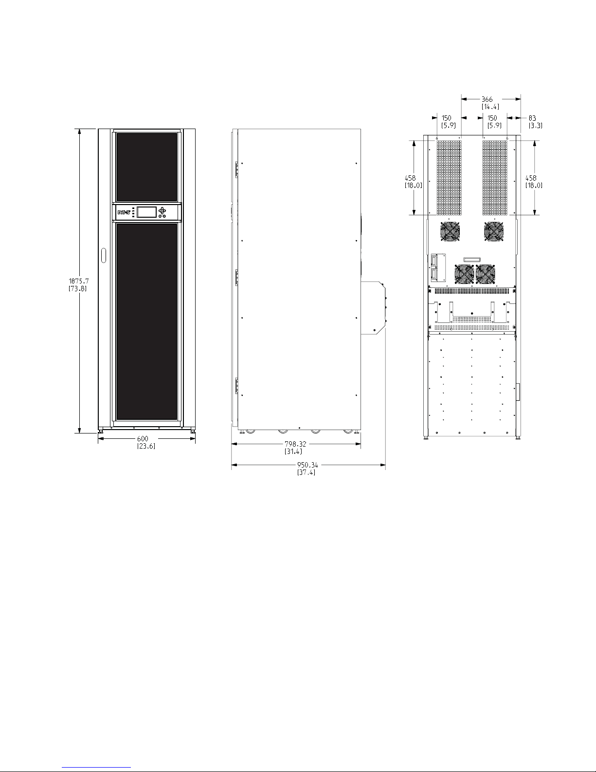
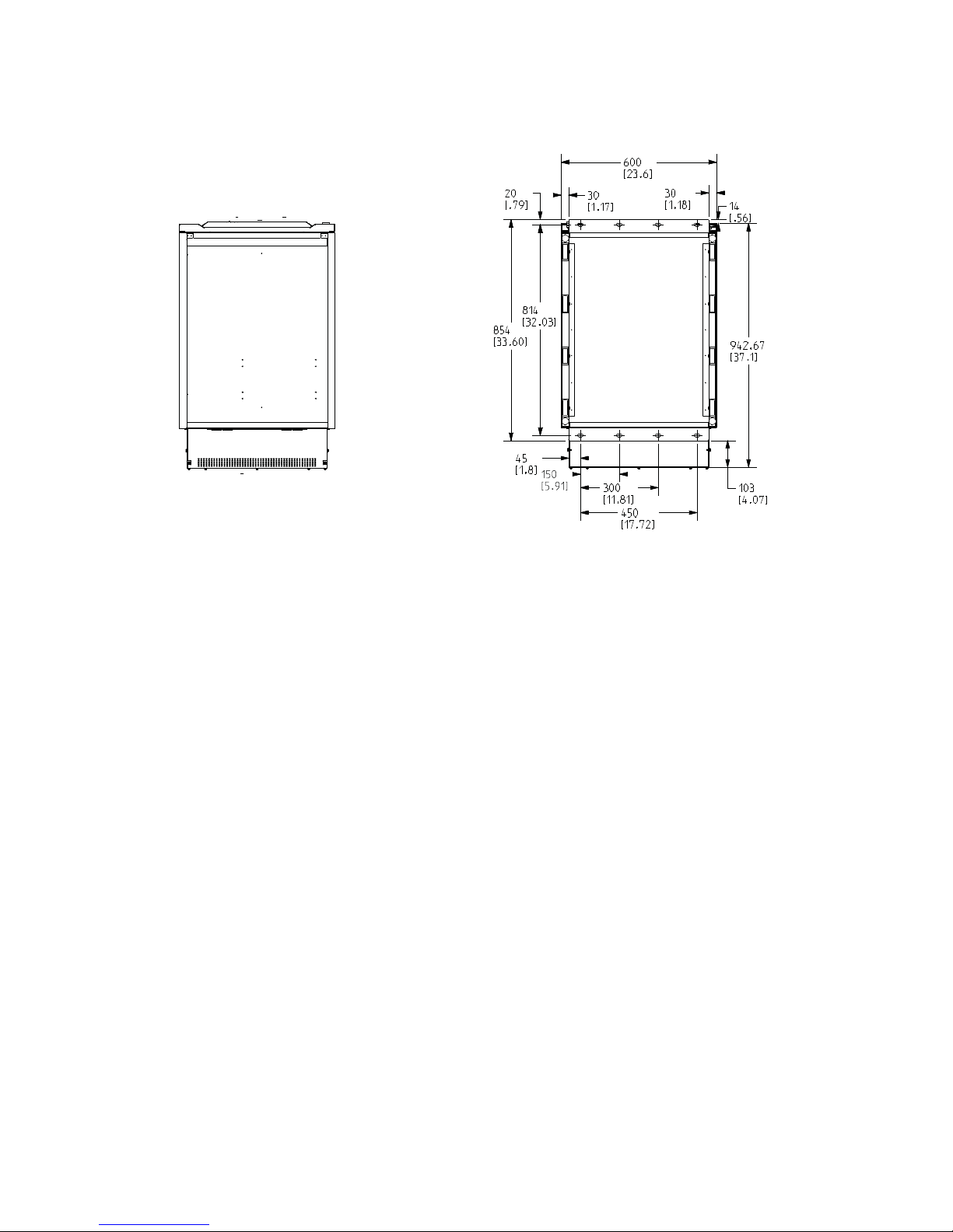
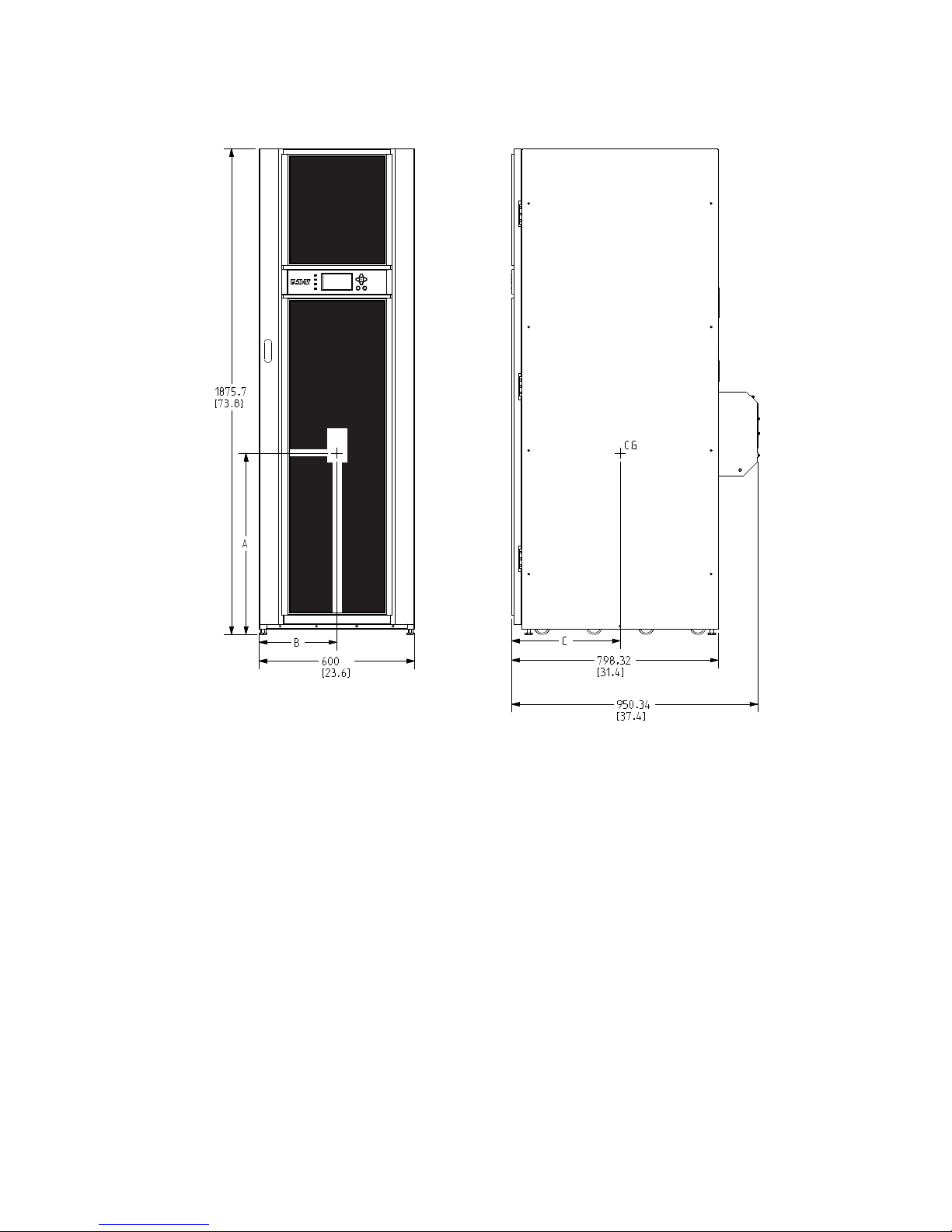
size requirements shown in Figure 3-1 through Figure 3-4. Dimensions are in millimeters (inches).
Eaton 9E UPS (40–60 kVA, 208/220V) Installation and Operation Manual P-164000058—Rev 4 www.eaton.com/powerquality 3-1

UPS Installation Plan and Unpacking
CAUTION
Table 3-1. UPS Cabinet Weights
Model
Eaton 9E-40 with internal batteries 675 (1488) 590 (1301) 8 at 74 (163)
Eaton 9E–60/40 with internal batteries
Eaton 9E–60/60 with internal batteries
Eaton 9E-40 without batteries
Eaton 9E–60/60 without batteries
The UPS cabinet uses forced air cooling to regulate internal component temperature. Air inlets are in the front
of the cabinet and outlets are in the back of the cabinet. Allow clearance in front of and in back of the cabinet
for proper air circulation. The clearances required around the UPS cabinet are shown in Table 3-2.
Table 3-2. UPS Cabinet Clearances
From Top of Cabinet 304.8 mm (12") working space
From Front of Cabinet 914.4 mm (36") working space
From Back of Cabinet Minimum of 203.2 mm (8”) for operation
From Right Side of Cabinet None Required
From Left Side of Cabinet None Required
Weight
kg (lb)
Shipping Installed Point Loading
765 (1686) 680 (1499) 8 at 85 (187)
405 (892) 320 (705) 8 at 40 (88)Eaton 9E–60/40 without batteries
Recommended 914.4 mm (36") for service
Clearances must comply with all applicable national and local codes. Flexible
conduit may be used to adjust between required operation and service clearances.
The basic environmental requirements for operation of the UPS are:
l
Ambient Temperature Range: 0–30C (32–86F)
l
Recommended Operating Range: 20–25C (68–77F)
l
Maximum Relative Humidity: 95%, noncondensing
If battery systems are located in the same room as the UPS, the battery manufacturer's
environmental requirements should be followed if they are more stringent than the UPS
requirements. Operating temperatures above the recommended range will result in decreased
battery life and performance, and may reduce or void the battery warranty.
The UPS ventilation requirements are shown in Table 3-3.
Table 3-3. Air Conditioning or Ventilation Requirements During Full Load Operation
Heat Rejection
Model Rating Input/Output Voltage
Eaton 9E-40
Eaton 9E–60/40
40 kVA 208/208 9.29 (2342)
BTU/hr x1000 (kg-cal/hr)
Eaton 9E–60/60 60 kVA 208/208 13.94 (3513)
3-2 Eaton 9E UPS (40–60 kVA, 208/220V) Installation and Operation Manual P-164000058—Rev 4 www.eaton.com/powerquality
UPS Installation Plan and Unpacking
Dimensions are in millimeters [inches]
Front
Right Side
Back
Figure 3-1. UPS Cabinet Dimensions (Front and Right Side Views)
Eaton 9E UPS (40–60 kVA, 208/220V) Installation and Operation Manual P-164000058—Rev 4 www.eaton.com/powerquality 3-3
UPS Installation Plan and Unpacking
Front
Front
Top
Bottom
Dimensions are in millimeters [inches]
Figure 3-2. UPS Cabinet Dimensions (Top and Bottom Views)
3-4 Eaton 9E UPS (40–60 kVA, 208/220V) Installation and Operation Manual P-164000058—Rev 4 www.eaton.com/powerquality
CG
Dimensions are in millimeters [inches]
Weight and Center of Gravity
ABC
Weight
kg (lb)
With Batteries (9E-40 – 6 Strings) 815 (32.1) 300 [11.8] 399 (15.7) 590 (1301)
With Batteries (9E–60/40 and 9E–60/60 – 8 Strings) 785 [30.9] 300 [11.8] 399 [15.7] 680 (1499)
Without Batteries 985 [38.8] 300 [11.8] 399 [15.7] 320 (705)
UPS Installation Plan and Unpacking
Figure 3-3. UPS Cabinet Center of Gravity
Eaton 9E UPS (40–60 kVA, 208/220V) Installation and Operation Manual P-164000058—Rev 4 www.eaton.com/powerquality 3-5
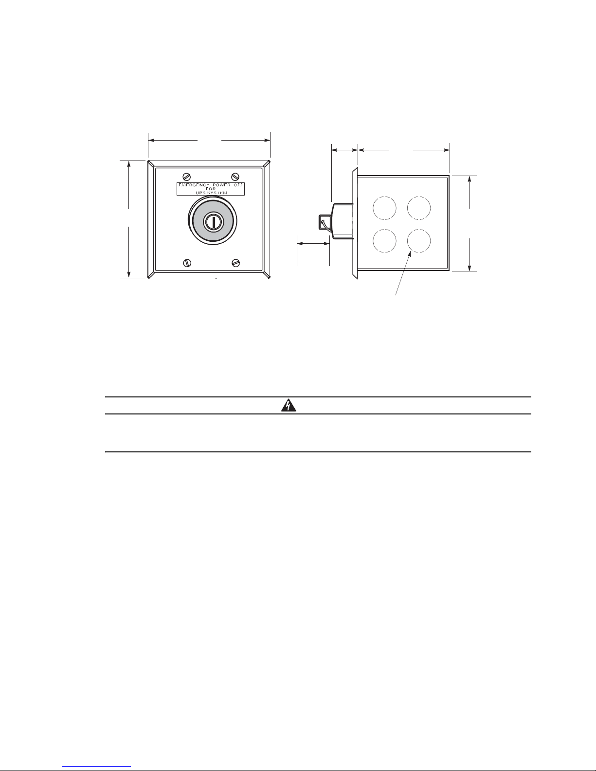
UPS Installation Plan and Unpacking
WARNING
115.8
[4.56]
114.3
[4.50]
0.87
[0.22]
88.9
[3.50]
1.57
[0.40]
95.3
[3.57]
Front View
1/2" Knockout Pattern
(Typical 5 Sides
Needed to
remove key
(Square)
Dimensions are in millimeters [inches]
Figure 3-4. Remote EPO Switch Dimensions
3.2.2 UPS System Power Wiring Preparation
Read and understand the following notes while planning and performing the installation:
As a result of the connected loads high leakage current is possible. Connection to earth ground is
required for safety and proper product operation. Do not check UPS operation by any action that
includes removal of the earth (ground) connection with loads attached.
l
Refer to national and local electrical codes for acceptable external wiring practices.
l
To allow for future kVA upgrades, consider installing a derated UPS using wiring and external overcurrent
protection breakers sized for a fully rated UPS.
l
For external wiring, use 90°C copper wire. Wire sizes listed in Table 3-4 are for copper wiring only. If wire is
run in an ambient temperature greater than 30°C, higher temperature wire and/or larger size wire may be
necessary. Wire sizes are based on using the specified breakers.
l
Wire ampacities are chosen from Table 310-16 of the National Electrical Code® (NEC®). Specification is for
copper wire with a 90°C rating.
l
Material and labor for external wiring requirements are to be supplied by designated personnel.
l
If installing an external maintenance bypass, all feeds to the UPS including the Rectifier Input Breaker (RIB)
(if installed) must have a service disconnect independent of the maintenance bypass power path. Most
maintenance bypass solutions provide UPS input feeds derived from but isolated from the maintenance
bypass power path. If the maintenance bypass solution being installed does not provide such functionality,
DO NOT use a single feeder breaker to supply both the UPS and the maintenance bypass.
3-6 Eaton 9E UPS (40–60 kVA, 208/220V) Installation and Operation Manual P-164000058—Rev 4 www.eaton.com/powerquality

UPS Installation Plan and Unpacking
l
The bypass feed into this equipment uses four wires. The rectifier feed into this equipment uses four wires.
The phases must be symmetrical about ground (from a Wye source) for proper equipment operation.
l
Parallel UPS input wiring size requirements and output wiring size requirements from the UPSs to the
Integrated Accessory Cabinet-Tie (IAC-T) or Integrated Accessory Cabinet-Tie and Bypass (IAC-TB) are the
same as listed in Table 3-4. Refer to the Eaton 9E Integrated Accessory Cabinet-Tie and Bypass Installation
and Operation Manual listed in paragraph 1.8 for additional IAC-T or IAC-TB wiring and termination
requirements.
For external wiring requirements, including the minimum AWG size of external wiring, see Table 3-4. Wire sizes
listed are for copper wiring only.
Table 3-4. Input/Output Ratings and External Wiring Requirements for the Eaton 9E-40, 9E–60/40, and 9E–60/60
Units Rating 50/60 Hz
Basic Unit Rating
Input and Output Voltage Volts 208/208 208/208
AC Input to UPS Rectifier (0.98 Minimum pF)
Full load current plus battery recharge current
(3) Phases, (1) Neutral, (1) Ground
Minimum Conductor Size (Phase A, B, and C)
Number per Phase
Minimum Conductor Size (Neutral)
Number per Phase
Minimum Conductor Size (Ground)
Number per Phase
AC Input to UPS Bypass (Five Wire, Dual-Feed)
Full Load Current
(3) Phases, (1) Neutral, (1) Ground
Minimum Conductor Size (Phase A, B, and C)
Number per Phase
Minimum Conductor Size (Neutral)
Number per Phase
Minimum Conductor Size (Ground)
Number per Phase
DC Input from External Battery
(1) Positive, (1) Negative, (1) Ground
Minimum Conductor Size (Phase Positive and Negative)
Number per Pole
Minimum Conductor Size (Ground)
Number per Phase
AC Output to Critical Load (Five Wire)
Full Load Current
(3) Phases, (1) Neutral, (1) Ground
Minimum Conductor Size (Phase A, B, and C)
Number per Phase
Minimum Conductor Size (Neutral)
Number per Phase
Minimum Conductor Size (Ground)
Number per Phase
NOTE Callout letters A, B, and D map to Figure 5-5. Callout letters A, B, C, and D map to Figure 5-6.
A
–
–
B
–
–
C
–
D
–
–
kVA
kW
Amps 128 185
AWG or kcmil
(each)
AWG or kcmil
(each)
AWG or kcmil
(each)
Amps 111 167
AWG or kcmil
(each)
AWG or kcmil
(each)
AWG or kcmil
(each)
Total Amps 165 248
AWG or kcmil
(each)
AWG or kcmil
(each)
Amps 111 167
AWG or kcmil
(each)
AWG or kcmil
(each)
AWG or kcmil
(each)
40
32
2/0
(1)
2/0
(2)
(1)
2/0
(1)
2/0
(2)
(1)
3/0
(1)
(1)
2/0
(1)
2/0
(2)
(1)
60
48
250
(1)
250
(2)
4
4
4
4
2
(1)
250
(1)
250
(2)
2
(1)
1/0
(2)
2
(1)
250
(1)
250
(2)
2
(1)
Eaton 9E UPS (40–60 kVA, 208/220V) Installation and Operation Manual P-164000058—Rev 4 www.eaton.com/powerquality 3-7

UPS Installation Plan and Unpacking
The power wiring terminals are pressure terminations, UL and CSA rated at 90°C. See Table 3-5 for external
power cable terminations.
Figure 4-7 and Figure 4-8 show the location of the UPS power cable terminals.
Table 3-5. UPS External Power Cable Terminations for the Eaton 9E-40, 9E–60/40, and 9E–60/60
Number and Size of Pressure
Termination
Terminal Function Terminal Function
AC Input to UPS Rectifier L1 Phase A 1 – #6-250 22.6 (200) 1/4 in. Hex
L2 Phase B 1 – #6-250 22.6 (200) 1/4 in. Hex
L3 Phase C 1 – #6-250 22.6 (200) 1/4 in. Hex
N Neutral 2 – #6-250 22.6 (200) 1/4 in. Hex
AC Input to Bypass L1 Phase A 1 – #6-250 22.6 (200) 1/4 in. Hex
L2 Phase B 1 – #6-250 22.6 (200) 1/4 in. Hex
L3 Phase C 1 – #6-250 22.6 (200) 1/4 in. Hex
N Neutral 2 – #6-250 22.6 (200) 1/4 in. Hex
AC Output to Critical Load L1 Phase A 1 – #6-250 22.6 (200) 1/4 in. Hex
L2 Phase B 1 – #6-250 22.6 (200) 1/4 in. Hex
L3 Phase C 1 – #6-250 22.6 (200) 1/4 in. Hex
N Neutral 2 – #6-250 22.6 (200) 1/4 in. Hex
DC Input from External Battery + Battery (+) 2 – #6-250 22.6 (200) 1/4 in. Hex
– Battery (-) 2 – #6-250 22.6 (200) 1/4 in. Hex
Customer Ground Ground Ground 4 – #6-300 31.1 (275) 5/16 in. Hex
NOTE Customer ground, sized in accordance with NEC Table 250.122, can be run in any conduit listed in Table 3-6.
AWG or kcmil
Tightening Torque
Nm (lb in)
Screw Size and Type
3-8 Eaton 9E UPS (40–60 kVA, 208/220V) Installation and Operation Manual P-164000058—Rev 4 www.eaton.com/powerquality
 Loading...