

Eaton 9910-E16, 9130, 9910-E15 Installation Manual

Eaton 9130 (9910-E15/E16) UPS
Installation Guide for IBM Applications
Asennusopas IBM-sovelluksille
Guide d'Installation pour Applications IBM
USV Installationsanleitung für IBM-Anwendungen
Guida all'Installazione per le Applicazioni IBM
Instrukcja instalowania dla zastosowań IBM
Руководство по установке в системах IBM
Guía de instalación para aplicaciones IBM
Installationshandledning för IBM-applikationer

This page intentionally left blank.
Eaton 9130 (9910-E15/E16) UPS
Installation Guide for IBM Applications
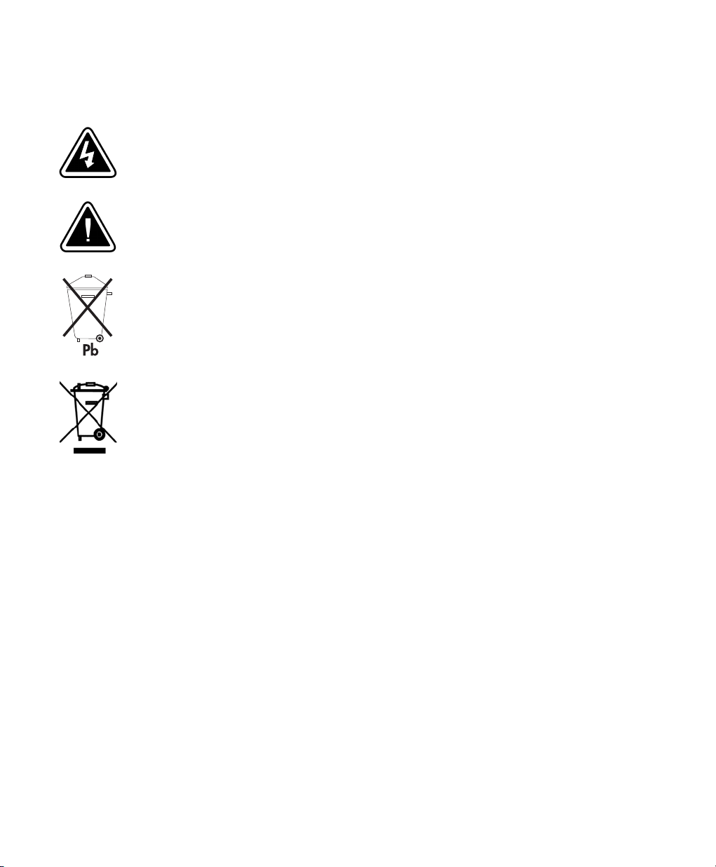
Special Symbols
The following are examples of symbols used on the UPS or accessories to alert you to important
information:
RISK OF ELECTRIC SHOCK - Indicates that a risk of electric shock is present and the
associated warning should be observed.
CAUTION: REFER TO OPERATOR'S MANUAL - Refer to your operator's manual for
additional information, such as important operating and maintenance instructions.
This symbol indicates that you should not discard the UPS or the UPS batteries in
the trash. This product contains sealed, lead‐acid batteries and must be disposed of
properly. For more information, contact your local recycling/reuse or hazardous
waste center.
This symbol indicates that you should not discard waste electrical or electronic
equipment (WEEE) in the trash. For proper disposal, contact your local
recycling/reuse or hazardous waste center.
IBM, AIX, xSeries, AS/400, OS/400, and RS/6000 are registered trademarks and System i, System p, OpenPower, and
i5/OS are trademarks of International Business Machines Corp.
Eaton and LanSafe are registered trademarks and ConnectUPS is a trademark of Eaton Corporation or its subsidiaries
and affiliates.
Burndy is a registered trademark of Framatone Connectors International.
ECopyright 2009 Eaton Corporation, Raleigh, NC, USA. All rights reserved. 164201783 2
No part of this document may be reproduced in any way without the express written approval of Eaton Corporation.

Table of Contents
1 Installation 6. . . . . . . . . . . . . . . . . . . . . . . . . . . . . . . . . . . . . . . . . . . . . . . . . . . . . . . .
Parts List 6. . . . . . . . . . . . . . . . . . . . . . . . . . . . . . . . . . . . . . . . . . . . . . . . . . . . . . . . . . . . . . . . . . . . . . . . . .
Unpacking the Cabinet 8. . . . . . . . . . . . . . . . . . . . . . . . . . . . . . . . . . . . . . . . . . . . . . . . . . . . . . . . . . . . . . . . .
Installation 8. . . . . . . . . . . . . . . . . . . . . . . . . . . . . . . . . . . . . . . . . . . . . . . . . . . . . . . . . . . . . . . . . . . . . . . .
Wiring Installation 9. . . . . . . . . . . . . . . . . . . . . . . . . . . . . . . . . . . . . . . . . . . . . . . . . . . . . . . . . . . . . . . . . . .
Installing the UPS 9. . . . . . . . . . . . . . . . . . . . . . . . . . . . . . . . . . . . . . . . . . . . . . . . . . . . . . . . . . . . . . . . .
Connecting the EBM(s) 11. . . . . . . . . . . . . . . . . . . . . . . . . . . . . . . . . . . . . . . . . . . . . . . . . . . . . . . . . . . . . .
Remote Emergency Power-off 13. . . . . . . . . . . . . . . . . . . . . . . . . . . . . . . . . . . . . . . . . . . . . . . . . . . . . . . . .
Power Connections and Startup 14. . . . . . . . . . . . . . . . . . . . . . . . . . . . . . . . . . . . . . . . . . . . . . . . . . . . . . . . . .
UPS Monitoring on the System i and AS/400 16. . . . . . . . . . . . . . . . . . . . . . . . . . . . . . . . . . . . . . . . . . . . . . . . .
UPS Rear Panels 17. . . . . . . . . . . . . . . . . . . . . . . . . . . . . . . . . . . . . . . . . . . . . . . . . . . . . . . . . . . . . . . . . . . . .
2 Operation 18. . . . . . . . . . . . . . . . . . . . . . . . . . . . . . . . . . . . . . . . . . . . . . . . . . . . . . . . . .
Control Panel Functions 18. . . . . . . . . . . . . . . . . . . . . . . . . . . . . . . . . . . . . . . . . . . . . . . . . . . . . . . . . . . . . . . .
Changing the Language 19. . . . . . . . . . . . . . . . . . . . . . . . . . . . . . . . . . . . . . . . . . . . . . . . . . . . . . . . . . . . .
Display Functions 19. . . . . . . . . . . . . . . . . . . . . . . . . . . . . . . . . . . . . . . . . . . . . . . . . . . . . . . . . . . . . . . . .
Operating Modes 20. . . . . . . . . . . . . . . . . . . . . . . . . . . . . . . . . . . . . . . . . . . . . . . . . . . . . . . . . . . . . . . . . . . .
Normal Mode 20. . . . . . . . . . . . . . . . . . . . . . . . . . . . . . . . . . . . . . . . . . . . . . . . . . . . . . . . . . . . . . . . . . . .
Battery Mode 20. . . . . . . . . . . . . . . . . . . . . . . . . . . . . . . . . . . . . . . . . . . . . . . . . . . . . . . . . . . . . . . . . . . .
Bypass Mode 21. . . . . . . . . . . . . . . . . . . . . . . . . . . . . . . . . . . . . . . . . . . . . . . . . . . . . . . . . . . . . . . . . . . .
Standby Mode 21. . . . . . . . . . . . . . . . . . . . . . . . . . . . . . . . . . . . . . . . . . . . . . . . . . . . . . . . . . . . . . . . . . .
UPS Startup and Shutdown 22. . . . . . . . . . . . . . . . . . . . . . . . . . . . . . . . . . . . . . . . . . . . . . . . . . . . . . . . . . . . .
Starting the UPS 22. . . . . . . . . . . . . . . . . . . . . . . . . . . . . . . . . . . . . . . . . . . . . . . . . . . . . . . . . . . . . . . . . .
Starting the UPS on Battery 23. . . . . . . . . . . . . . . . . . . . . . . . . . . . . . . . . . . . . . . . . . . . . . . . . . . . . . . . . .
UPS Shutdown 23. . . . . . . . . . . . . . . . . . . . . . . . . . . . . . . . . . . . . . . . . . . . . . . . . . . . . . . . . . . . . . . . . . .
Configuring the UPS for EBMs 24. . . . . . . . . . . . . . . . . . . . . . . . . . . . . . . . . . . . . . . . . . . . . . . . . . . . . . . . . . .
3 Communication Options 25. . . . . . . . . . . . . . . . . . . . . . . . . . . . . . . . . . . . . . . . . . . . . .
System i Interface Overview 26. . . . . . . . . . . . . . . . . . . . . . . . . . . . . . . . . . . . . . . . . . . . . . . . . . . . . . . . . . . . .
iSeries or AS/400 Interface Overview 27. . . . . . . . . . . . . . . . . . . . . . . . . . . . . . . . . . . . . . . . . . . . . . . . . . . . . .
Serial (TTY) Interface Overview 28. . . . . . . . . . . . . . . . . . . . . . . . . . . . . . . . . . . . . . . . . . . . . . . . . . . . . . . . . . .
4 Service and Support 30. . . . . . . . . . . . . . . . . . . . . . . . . . . . . . . . . . . . . . . . . . . . . . . . .
EATON 9130 (9910-E15/E16) UPS Installation Guide for IBM® Applications S 164201783 Rev 2
5

Chapter 1 Installation
Parts List
IBM part numbers are subject to change without notice.
Table 1. E15 Base Configuration (44V6738)
Quantity IBM MN IBM FC IBM PN Eaton® PN Description
1 E15 — 44V6738 103007458-3991 E15 UPS 1500 VA, 1350W, 120V, which includes the following:
Table 2. E16 Base Configuration (44V6739)
Quantity IBM MN IBM FC IBM PN Eaton PN Description
1 E16 — 44V6739 103007459-3991 E16 UPS 1500 VA, 1350W, 230V, which includes the following:
S (1) Relay Interface Card (1014018)
S (1) 9406 UPS to AS/400 Communication cable (7.6m/25 ft)
(103004349-5501)
S (1) Relay Interface Card Instructions (1018946)
S (1) Eaton 9130 (9910-E15/E16) Installation Guide for IBM
Applications (164201783)
S (1) Eaton 9130 UPS (1500 VA) User's Guide (164201718)
S (1) Software Suite CD (619-00205-15)
S (1) USB Cable (1.8m/6 ft) (720-65037-01)
S (1) RS-232 Cable (1.8m/6 ft) (720-60258-00)
S (3) C13 to 5-15P Equipment Power Cords, UL and cUL rated,
(1.8m/6 ft) (108-00101-01A)
S (2) Cord retention ties (520-05408)
S (1) Relay Interface Card (1014018)
S (1) 9406 UPS to AS/400 Communication cable (7.6m/25 ft)
(103004349-5501)
S (1) Relay Interface Card Instructions (1018946)
S (1) Eaton 9130 (9910-E15/E16) Installation Guide for IBM
Applications (164201783)
S (1) Eaton 9130 UPS (1500 VA) User's Guide (164201718)
S (1) Software Suite CD (619-00205-15)
S (1) USB Cable (1.8m/6 ft) (720-65037-01)
S (1) RS-232 Cable (1.8m/6 ft) (720-60258-00)
S (6) C13 to C14 Equipment Power Cords, Harmonized
(1.8m/6 ft) (108-00276-00)
S (2) Cord retention ties (520-05407)
6
EATON 9130 (9910-E15/E16) UPS Installation Guide for IBM® Applications S 164201783 Rev 2

INSTALLATION
Table 3. E15/E16 Options Configuration Matrix
IBMMNIBMFCIBM
PN
— 2941 44V7917 103006826
— 6647 44V6740 103007460-3991 Extended Battery Module (EBM) for 1500 VA Min: 0, Max: 4
Eaton
PN
Description Quantity
ConnectUPS -MS Web/SNMP Card
t
Min: 0, Max: 1
Table 4. E15/E16 6647 EBM Components (44V6740)
Quantity IBM MN IBM FC IBM PN Eaton PN Description
1 — 6647 44V6740 103007460-3991 E15/E16 6647 EBM, which includes the following:
S (1) EBM cable (0.33m/1.08 ft) (720-E0500-00)
S (1) Eaton 9130 Extended Battery Module (EBM) User's
Guide (1642011752)
EATON 9130 (9910-E15/E16) UPS Installation Guide for IBM® Applications S 164201783 Rev 2
7

INSTALLATION
Unpacking the Cabinet
S Unpacking the cabinet in a low-temperature environment may cause condensation to
occur in and on the cabinet. Do not install the cabinet until the inside and outside of the
cabinet are absolutely dry (hazard of electric shock).
S The cabinet is heavy (19.0 kg/41.9 lb). Use caution to unpack and move the cabinet.
Use care when moving and opening the carton. Leave the components
packaged until ready to install.
To unpack the cabinet and accessories:
1. Open the outer carton and remove the accessories packaged with
the cabinet.
2. Carefully lift the cabinet out of the outer carton.
3. Discard or recycle the packaging in a responsible manner, or store it
for future use.
C
A U T I O N
Installation
8
EATON 9130 (9910-E15/E16) UPS Installation Guide for IBM® Applications S 164201783 Rev 2
Place the cabinet in a protected area that has adequate airflow and is
free of humidity, flammable gas, and corrosion.
C
A U T I O N
The cabinet is heavy (19.0 kg/41.9 lb). Removing the cabinet from its carton requires a
minimum of two people.
To install the cabinet:
1. Place the UPS on a flat, stable surface in its final location.
2. If installing additional cabinets, place them next to the UPS in their
final location.
3. Continue to the following section, “Wiring Installation.”
Wiring Installation
INSTALLATION
This section explains:
S Installing the UPS, including connecting the UPS internal batteries
S Connecting any optional EBMs
Installing the UPS
NOTE Do not make unauthorized changes to the UPS; otherwise, damage may occur to
your equipment and void your warranty.
NOTE Do not connect the UPS power cord to utility until after installation is completed.
To install the UPS:
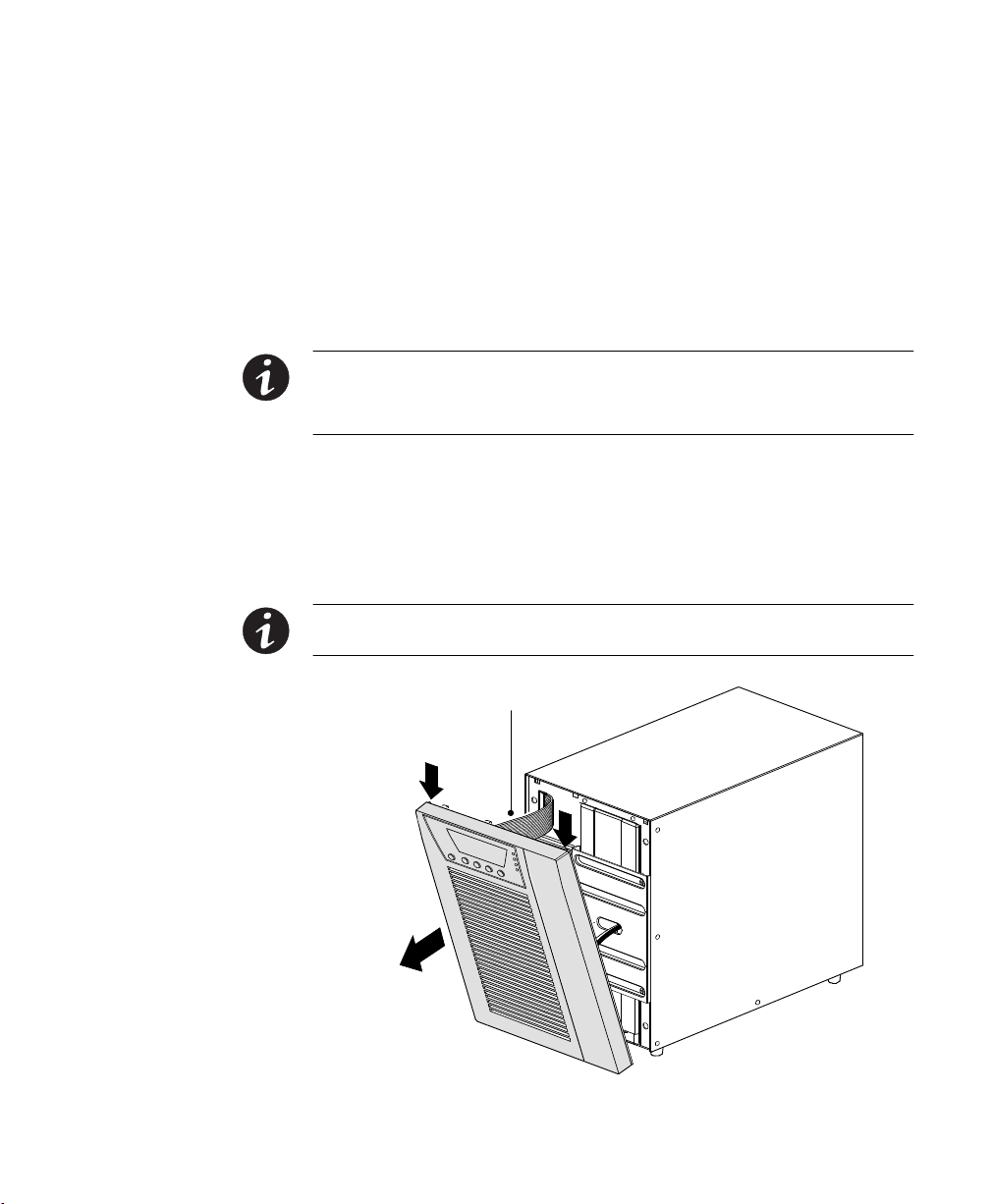
1. Remove the UPS front cover (see Figure 1).
To remove the cover, push down on the top of the cover and pull
the cover toward you to unclip it from the cabinet.
NOTE A ribbon cable connects the LCD control panel to the UPS. Do not pull on the cable
or disconnect it.
NOTE Leave
ribbon cable
connected.
Figure 1. Removing the UPS Front Cover
EATON 9130 (9910-E15/E16) UPS Installation Guide for IBM® Applications S 164201783 Rev 2
9
INSTALLATION
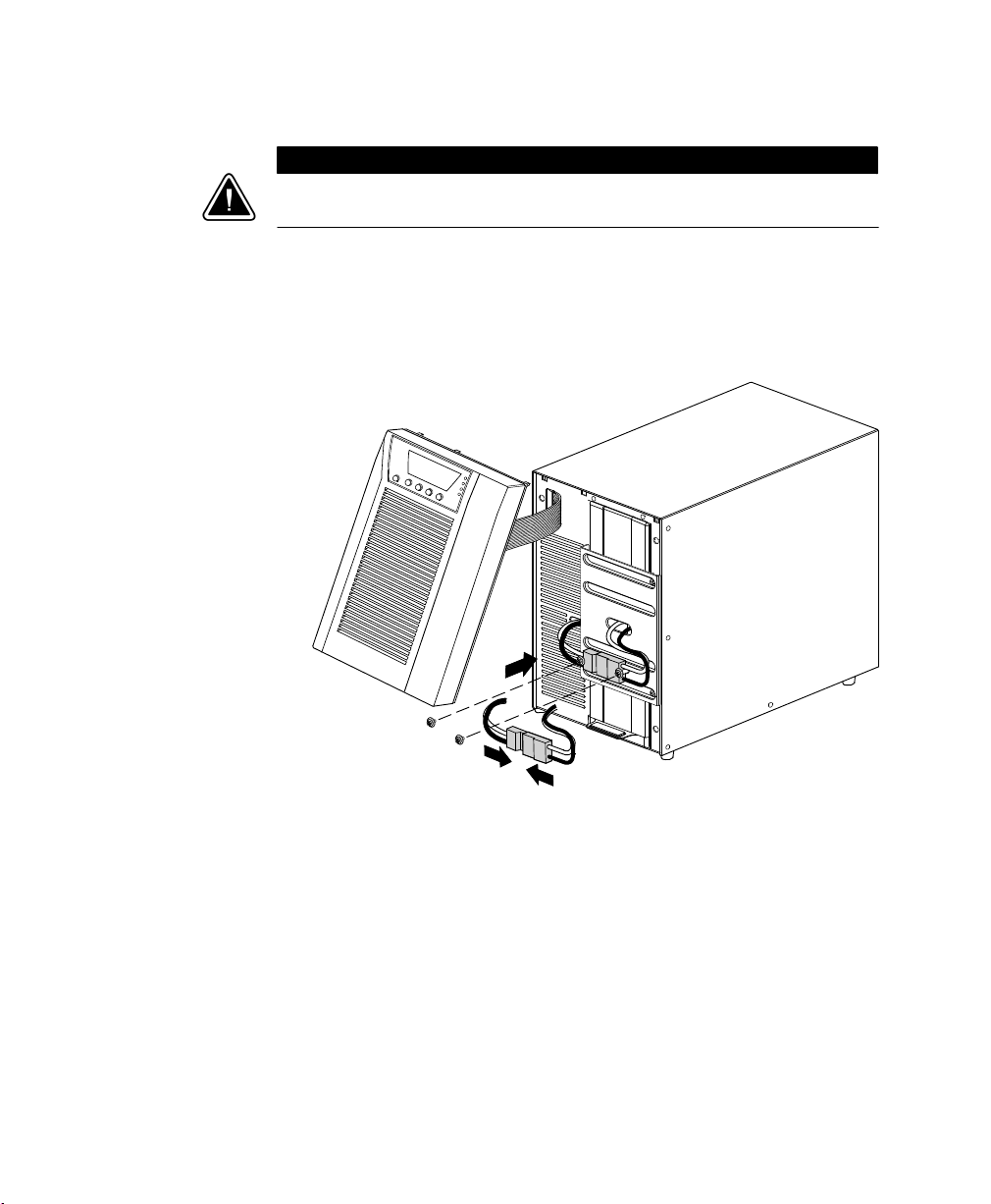
C A U T I O N
A small amount of arcing may occur when connecting the internal batteries. This is normal
and will not harm personnel. Connect the cables quickly and firmly.
2. Connect the internal battery connector (see Figure 2).
Connect the white connectors together, connecting red to red, and
black to black. Press the two parts tightly together to ensure a
proper connection.
10
Figure 2. Connecting the UPS Internal Batteries
3. Remove the two screws from the screw mounts and retain (see
Figure 2).
4. Place the battery connector between the screw mounts. Reinstall
the two screws to hold the connector in place.
5. Replace the UPS front cover.
To replace the cover, verify that the ribbon cable is protected, then
insert the clips on the back of the cover into the cabinet and push
firmly to snap the cover into place.
EATON 9130 (9910-E15/E16) UPS Installation Guide for IBM® Applications S 164201783 Rev 2

INSTALLATION
6. If you are installing power management software, connect your
computer to one of the communication ports or optional
connectivity card. For the communication ports, use an appropriate
cable as follows:
S For the AS/400. Use the supplied AS/400 communication cable.
The “AS/400” end of the cable connects to the port marked
“J14” or “UPS”on the AS/400 rear panel.
S For PCs and workstations. Use the communication cable supplied
with the power management software CD.
7. If an emergency power-off (disconnect) switch is required by local
codes, see “Remote Emergency Power-off” (REPO) on page 13 to
install the REPO switch before powering on the UPS.
8. If you are installing EBM(s), continue to the following section,
“Connecting the EBM(s).” Otherwise, continue to “Starting the
UPS” on page 22.
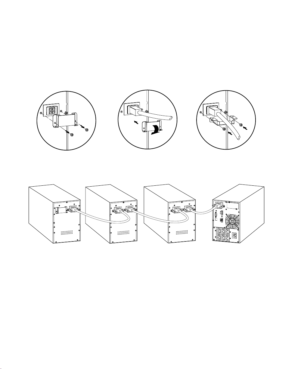
Connecting the EBM(s)
To install the optional EBM(s) for a UPS:
1. On the rear of the UPS, remove the cable retention clip covering
the battery connector. Retain the clip and screws. See Figure 3.
2. Installations with one EBM only. Remove the cable retention clip
covering the right battery connector. Retain the clip and screws.
3. Installations with more than one EBM. For all EBMs except the last
EBM, remove the cable retention clips covering both battery
connectors. Do not remove the clip from the second battery
connector on the last EBM. Retain the clips and screws.
C A U T I O N
A small amount of arcing may occur when connecting an EBM to the UPS. This is normal and
will not harm personnel. Insert the EBM cable into the UPS battery connector quickly and
firmly.
4. Plug the EBM cable(s) into the battery connector(s) as shown in
Figure 3. Up to four EBMs may be connected to the UPS.
5. For each cable retention clip removed, rotate the clip and install it
under each EBM cable connection using the retained screws.
EATON 9130 (9910-E15/E16) UPS Installation Guide for IBM® Applications S 164201783 Rev 2
11
INSTALLATION
6. Verify that the EBM connections are tight and that adequate bend
radius and strain relief exist for each cable.
7. Continue to “Starting the UPS” on page 22.
Remove cable retention clip. Plug in EBM cable. Rotate clip. Reinstall cable retention clip.
12
Figure 3. Connecting the EBMs
EATON 9130 (9910-E15/E16) UPS Installation Guide for IBM® Applications S 164201783 Rev 2

INSTALLATION
Remote Emergency Power-off
REPO is used to shut down the UPS from a distance. This feature can
be used for shutting down the load and the UPS by thermal relay, for
instance in the event of room overtemperature. When REPO is
activated, the UPS shuts down the output and all its power converters
immediately. The UPS remains on to alarm the fault.
W A R N I N G
The REPO circuit is an IEC 60950 safety extra low voltage (SELV) circuit. This circuit must be
separated from any hazardous voltage circuits by reinforced insulation.
C A U T I O N
S The REPO must not be connected to any utility connected circuits. Reinforced insulation
to the utility is required. The REPO switch must have a minimum rating of 24 Vdc and
20 mA and be a dedicated latching-type switch not tied into any other circuit. The REPO
signal must remain active for at least 250 ms for proper operation.
S To ensure the UPS stops supplying power to the load during any mode of operation, the
input power must be disconnected from the UPS when the emergency power-off function
is activated.
NOTE For Europe, the emergency switch requirements are detailed in Harmonized
document HD-384-48 S1, “Electrical Installation of the Buildings, Part 4: Protection for Safety,
Chapter 46: Isolation and Switching.”
REPO Connections
Wire Function Terminal Wire Size Rating Suggested Wire Size
REPO
NOTE Leave the REPO connector installed in the REPO port on the UPS even if the REPO
function is not needed.
EATON 9130 (9910-E15/E16) UPS Installation Guide for IBM® Applications S 164201783 Rev 2
L1
L2
4–0.32 mm2 (12–22 AWG) 0.82 mm2 (18 AWG)
13

INSTALLATION
See “UPS Rear Panels” on page 17 for REPO location. Figure 4 shows a
schematic of the REPO connector contacts.
You can set the REPO polarity. See the “REPO Input Polarity” setting in
“User Settings” in the UPS user's guide.
NOTE Depending on user configuration, the pins must be shorted or open to keep the UPS
running. To restart the UPS, reconnect (re-open) the REPO connector pins and turn on the UPS
manually. Maximum resistance in the shorted loop is 10 ohm.
NOTE Always test the REPO function before applying your critical load to avoid accidental
load loss.
Power Connections and Startup
To start up the UPS:
+ Polarity
1
– Polarity
2
Figure 4. REPO Connections
REPO
14
1. If optional
the UPS (see page
EBMs are installed, verify that the EBMs are connected to
11).
2. Verify that the internal bateries are connected (see page 10).
3. Plug the equipment to be protected into the UPS, but do not turn
on the protected equipment.
4. Make any necessary provisions for cord retention and strain relief.
NOTE DO NOT protect laser printers with the UPS because of the exceptionally high power
requirements of the heating elements.
5. E16 models only. Plug the power cord provided with the IBM
equipment into the input connector on the UPS rear panel (see
Figure 6 and Figure 5 on page 17).
6. Plug the UPS power cord into a power outlet.
The UPS front panel display illuminates and shows a status of “UPS
initializing...”
7. Verify that the UPS transfers to Standby mode (”UPS on standby”).
EATON 9130 (9910-E15/E16) UPS Installation Guide for IBM® Applications S 164201783 Rev 2

INSTALLATION
8. Press the button on the UPS front panel for at least one second.
The UPS front panel display changes status to “UPS starting...”
9. Check the UPS front panel display for active alarms or notices.
Resolve any active alarms before continuing. See
“Troubleshooting” in the UPS user's guide.
If the
indicator is on, do not proceed until all alarms are clear.
Check the UPS status from the front panel to view the active
alarms. Correct the alarms and restart if necessary.
10. Verify that the
indicator illuminates solid, indicating that the
UPS is operating normally and any loads are powered.
The UPS should be in Normal mode.
ESC
11. Press the
button until the start screen appears.
12. If optional EBMs are installed, see “Configuring the UPS for EBMs”
on page 24 to set the number of installed EBMs.
13. To change other factory-set defaults, see the “Operation” section.
NOTE IBM recommends setting the date and time.
NOTE At initial startup, the UPS sets system frequency according to input line frequency
(input frequency auto-sensing is enabled by default). After initial startup, auto-sensing is
disabled until manually re-enabled by output frequency setting.
NOTE At initial startup, input voltage auto-sensing is disabled by default. When manually
enabled by output voltage setting, at the next AC startup the UPS sets output voltage
according to input line voltage. After the subsequent startup, auto-sensing is disabled until
manually re-enabled by output voltage setting.
14. If you installed an optional REPO, test the REPO function:
Activate the external REPO switch. Verify the status change on the
UPS display.
Deactivate the external REPO switch and restart the UPS.
EATON 9130 (9910-E15/E16) UPS Installation Guide for IBM® Applications S 164201783 Rev 2
15

INSTALLATION
NOTE The internal batteries charge to 90% capacity in less than 3 hours. However, Eaton
recommends that the batteries charge for 48 hours after installation or long-term storage.
15. Keep your UPS firmware updated. See the UPS user's guide for
more information.
If you have questions about either the E15 or the E16 UPS, the following
options are available:
S For product information, visit www.eaton.com/ibm.
S For answers to frequently asked questions, visit our FAQ database at
www.eaton.com/ibm and select General Knowledge > Frequently
Asked Questions.
S If your question is not in the FAQ database, submit the question to
“Ask the Expert” at www.eaton.com/ibm.
S If you need additional information, contact the IBM office or Business
Partner servicing your account.
UPS Monitoring on the System i and AS/400
To set the system for UPS monitoring:
16
1. Set the QUPSDLYTIM system value for the UPS monitoring
feature.
2. UPS monitoring is a standard feature of the System i (AS/400)
operating system. QUPSDLYTIM is a timer that tells the system
how long to run on UPS power before shutting down. Each system
is initially assigned a default value for QUPSDLYTIM. A complete
description of QUPSDLYTIM is provided on the AS/400 Information
Center Internet Site at:
http://publib.boulder.ibm.com/pubs/html/as400/ic2924/info/index.htm
Select System Administration and Maintenance.
C A U T I O N
The *NOMAX value tells the AS/400 to use customized shutdown software, and if none is
available it will begin shutdown immediately when utility power fails. Do not set
QUPSDLYTIM to “*NOMAX” unless you understand the implications of the “*NOMAX”
function as described at the AS/400 Information Center Internet Site.
EATON 9130 (9910-E15/E16) UPS Installation Guide for IBM® Applications S 164201783 Rev 2
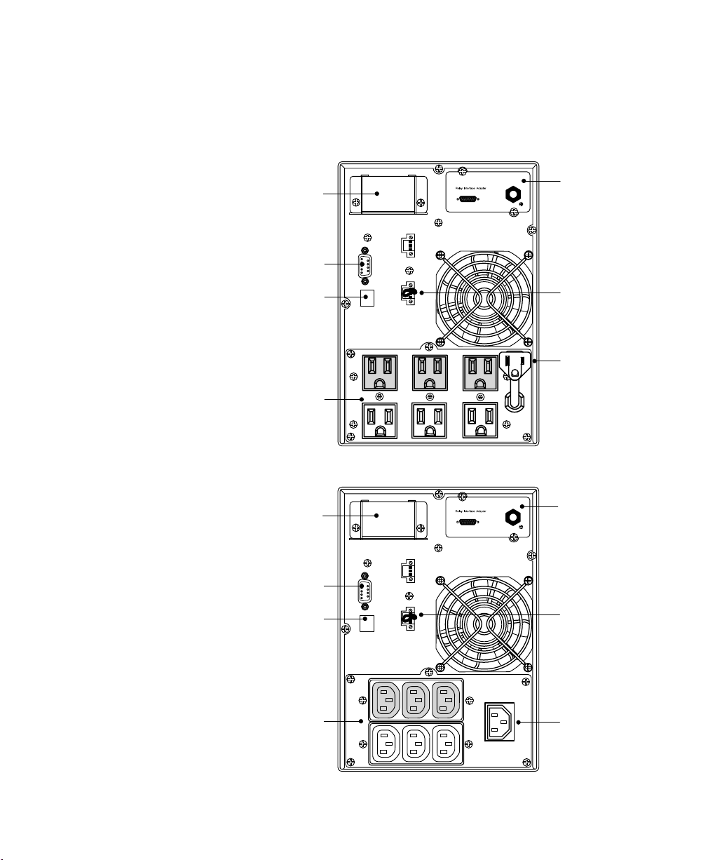
UPS Rear Panels
INSTALLATION
This section shows the rear panels of the E15 and E16 UPS models.
EBM Connector
Cover
Communication
Port
USB Port
Six 5-15
Receptacles
EBM Connector
Cover
Communication
Port
USB Port
Relay Interface
Card
REPO
Attached Power
Cord
Figure 5. E15 UPS Model Rear Panel
Relay Interface
Card
REPO
Six IEC 320-C13
Receptacles
IEC 320-C14
Input Connector
Figure 6. E16 UPS Model Rear Panel
EATON 9130 (9910-E15/E16) UPS Installation Guide for IBM® Applications S 164201783 Rev 2
17
Chapter 2 Operation
This chapter contains information on how to use the Eaton 9130,
including front panel operation, operating modes, UPS startup and
shutdown, transferring the UPS between modes, retrieving the Event
Log, setting the power strategy, and configuring bypass settings, load
segments, and battery settings.
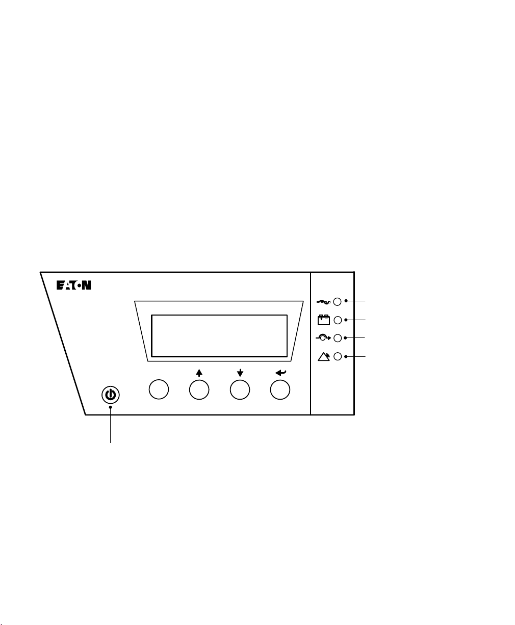
Control Panel Functions
The UPS has a four-button graphical LCD with backlight. It provides
useful information about the UPS itself, load status, events,
measurements, and settings (see Figure 7).
esc
Power On Indicator (green)
On Battery Indicator (yellow)
Bypass Indicator (yellow)
Alarm Indicator (red)
18
Escape Up Down Enter
On/Off Button
Figure 7. Eaton 9130 Control Panel
EATON 9130 (9910-E15/E16) UPS Installation Guide for IBM® Applications S 164201783 Rev 2
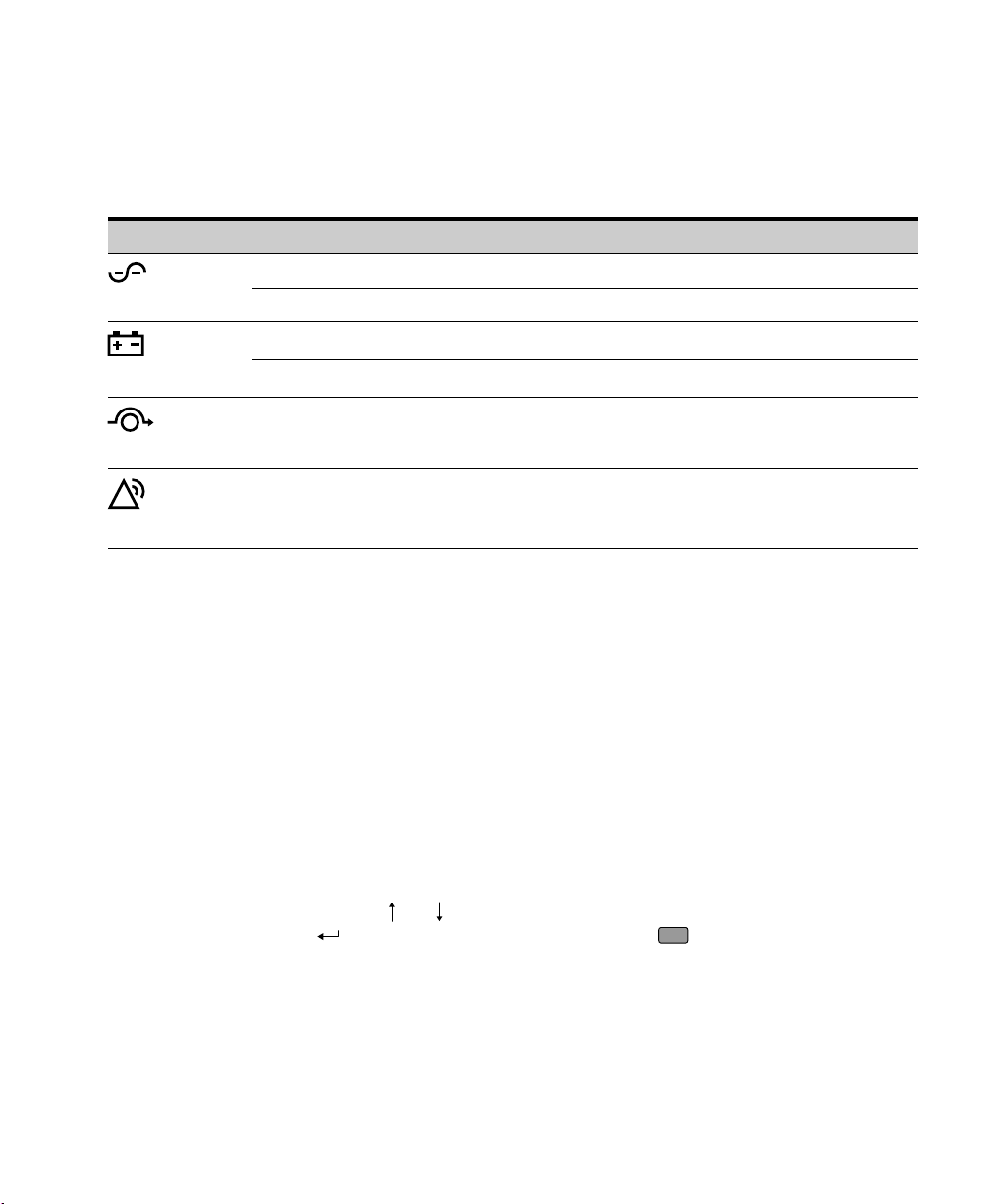
Table 5 shows the indicator status and description.
Table 5. Indicator Descriptions
Indicator Status Description
On The UPS is operating normally.
OPERATION
Green
Yellow
Yellow
Red
Flashing A new information message is active.
On The UPS is in Battery mode.
Flashing The battery voltage is below the warning level.
On The UPS is in Bypass mode.
The UPS is operating normally on bypass during High Efficiency operation.
On The UPS has an active alarm or fault. See “Troubleshooting” in the UPS user's
guide for additional information.
Changing the Language
Press and hold the first button on the left for approximately three
seconds to select the language menu. This action is possible from any
LCD menu screen.
Display Functions
As the default or after 15 minutes of inactivity, the LCD displays the
start screen.
The backlit LCD automatically dims after 15 minutes of inactivity. Press
any button to restore the screen.
Press any button to activate the menu options. Use the two middle
buttons (
(
and ) to scroll through the menu structure. Press the Enter
) button to select an option. Press the
ESC
button to cancel or return
to the previous menu.
EATON 9130 (9910-E15/E16) UPS Installation Guide for IBM® Applications S 164201783 Rev 2
19

OPERATION
Operating Modes
The Eaton 9130 front panel indicates the UPS status through the UPS
indicators (see Figure 7 on page 18).
Normal Mode
During Normal mode, the indicator illuminates solid and the UPS is
powered from the utility. The UPS monitors and charges the batteries as
needed and provides filtered power protection to your equipment.
The UPS may at times silently implement a High Alert mode, usually
when incoming utility conditions are unfavorable. In High Alert mode,
the UPS disables the battery support test to ensure maximum capacity
from the batteries if needed. The UPS will remain in High Alert for
24 hours or until changed by a Power Strategy command before
returning to its previous mode.
Optional High Efficiency and Energy Saving settings minimize heat
contribution to the rack environment. See “User Settings” in the UPS
user's guide.
20
Battery Mode
When the UPS is operating during a power outage, the alarm beeps
once every five seconds and the
When the utility power returns, the UPS transfers to Normal mode
operation while the battery recharges.
If battery capacity becomes low while in Battery mode, the
flashes slowly and the audible alarm beeps once every second. If the
“Battery Low” alarm is set, the
warning is approximate, and the actual time to shutdown may vary
significantly.
NOTE Depending on the UPS load and the number of Extended Battery Modules (EBMs)
connected, the “Battery Low” warning may occur before the batteries reach 25% capacity.
Refer to the UPS user's guide for estimated runtimes.
When utility power is restored after the UPS shuts down, the UPS
automatically restarts.
EATON 9130 (9910-E15/E16) UPS Installation Guide for IBM® Applications S 164201783 Rev 2
indicator illuminates solid.
indicator also illuminates solid. This
indicator

OPERATION
Bypass Mode
In the event of a UPS overload or internal failure, the UPS transfers your
equipment to utility power. Battery mode is not available and your
equipment is not protected; however, the utility power continues to be
passively filtered by the UPS. The
indicator illuminates.
The UPS remains in Bypass mode for at least 5 seconds (if the bypass
source remains acceptable). If three transfers to Bypass occur within
10 minutes for any reason other than user command, the UPS locks in
Bypass for 1 hour or until any control button is pressed.
The UPS transfers to Bypass mode when:
S The user activates Bypass mode through the front panel.
S The UPS detects an internal failure.
S The UPS has an overtemperature condition.
S The UPS has an overload condition.
NOTE The UPS shuts down after a specified delay for overload conditions listed in
“Troubleshooting” in the UPS user's guide. The UPS remains on to alarm the fault.
Standby Mode
When the UPS is turned off and remains plugged into a power outlet,
the UPS is in Standby mode. The
power is not available to your equipment. The battery recharges when
necessary, and the communication bay is powered.
If utility fails and output turns off due to drained batteries or UPS internal
failure, the UPS alarms in Standby mode and powers the communication
bay for 1 hour 30 minutes or until battery voltage drops below 1.75 volts
per cell (whichever occurs first).
If utility fails while the UPS is in Standby mode, the logic power supply
turns off in approximately 10 seconds.
If the UPS is waiting on commands and utility fails, unit and logic power
turn off in approximately 30 seconds.
EATON 9130 (9910-E15/E16) UPS Installation Guide for IBM® Applications S 164201783 Rev 2
indicator is off, indicating that
21

OPERATION
UPS Startup and Shutdown
To start up or shut down the UPS, see:
S “Starting the UPS” on page 22
S “Starting the UPS on Battery” on page 23
S “UPS Shutdown” on page 23
Starting the UPS
To start the UPS:
1. Verify that the UPS power cord is plugged in.
2. Switch on utility power where the UPS is connected.
The UPS front panel display illuminates and shows a status of “UPS
initializing...”.
3. Verify that the UPS transfers to Standby mode (”UPS on standby”).
22
4. Press the
button on the UPS front panel for at least one second.
The UPS front panel display changes status to “UPS starting...”.
5. Check the UPS front panel display for active alarms or notices.
Resolve any active alarms before continuing. Refer to
“Troubleshooting” in the UPS user's guide.
If the
indicator is on, do not proceed until all alarms are clear.
Check the UPS status from the front panel to view the active
alarms. Correct the alarms and restart if necessary.
6. Verify that the
indicator illuminates solid, indicating that the
UPS is operating normally and any loads are powered.
The UPS should be in Normal mode.
ESC
7. Press the
EATON 9130 (9910-E15/E16) UPS Installation Guide for IBM® Applications S 164201783 Rev 2
button until the start screen appears.
OPERATION
Starting the UPS on Battery
NOTE Before using this feature, the UPS must have been powered by utility power with
output enabled at least once.
NOTE Battery start can be disabled. See “User Settings” in the UPS user's guide.
To start the UPS on battery:
1. Press the
button on the UPS front panel until the UPS front
panel display illuminates and shows a status of “UPS starting...”.
The UPS cycles through Standby mode to Battery mode. The
indicator illuminates solid. The UPS supplies power to your
equipment.
2. Check the UPS front panel display for active alarms or notices
besides the “UPS on Battery” notice and notices that indicate
missing utility power. Resolve any active alarms before continuing.
Refer to “Troubleshooting” in the UPS user's guide.
Check the UPS status from the front panel to view the active
alarms. Correct the alarms and restart if necessary.
ESC
3. Press the
button until the start screen appears.
UPS Shutdown
To shut down the UPS:
1. Press the
The UPS starts to beep and shows a status of “UPS off pending...”.
The UPS then transfers to Standby mode, and the
turns off.
button on the front panel for three seconds.
indicator
NOTE Releasing the button before three seconds returns the UPS to its original
operating mode.
2. Switch off utility power where the UPS is connected.
EATON 9130 (9910-E15/E16) UPS Installation Guide for IBM® Applications S 164201783 Rev 2
23

OPERATION
Configuring the UPS for EBMs
To ensure maximum battery runtime, configure the UPS for the correct
number of EBMs:
1. Press any button on the front panel display to activate the menu
options, then select SETTINGS, USER SETTINGS, and NUMBER OF
BATTERY STRINGS.
2. Use the
or buttons to select the number of battery strings
according to your UPS configuration:
All UPS and EBM Cabinets
UPS only (internal batteries) 1 (default)
UPS + 1 EBM 3
UPS + 2 EBMs 5
UPS + 3 EBMs 7
UPS + 4 EBMs 9
NOTE If 0 is selected, no batteries are connected and all battery-related
alarms are disabled.
NOTE The UPS contains one battery string; each EBM contains two battery
strings.
Number of Battery Strings
3. Press the button to save the setting.
4. Press the
ESC
button until the start screen appears.
24
EATON 9130 (9910-E15/E16) UPS Installation Guide for IBM® Applications S 164201783 Rev 2

Chapter 3 Communication Options
If you want the UPS to communicate with your computer, use Table 6 to
determine which communication option is correct for your application.
Table 6. Communication Options
Application
IBM System it Server — X
IBM System p, OpenPowert, or xSeries
Server with Single Serial (TTY)
Connection
IBM System pt, OpenPower, or xSeries
Server and/or Network (WebServer)
Connection (UPS as a node)
IBM System p, OpenPower, or xSeries
Server with Logical Partitions (LPARs)
Follow the installation instructions with the Software Suite CD. This
document shows the communication option overviews. For additional
information and a current listing of supported operating systems, go to
www.eaton.com/powerquality.
Software Suite CD
®
and Serial Cable
X X
X —
Not Supported
Relay Interface Card
and Cable
EATON 9130 (9910-E15/E16) UPS Installation Guide for IBM® Applications S 164201783 Rev 2
25
COMMUNICATION OPTIONS
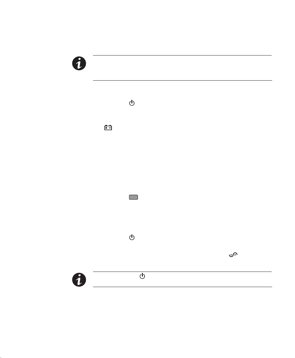
System i Interface Overview
To connect the UPS to a System i, you need:
S An Eaton-supplied AS/400 interface cable (labeled 103004349-5501),
included with the UPS
S An IBM-supplied UPS interface cable (labeled 1827), included with
the server
Connect the cables as shown in Figure 8.
UPS Interface Cable
(labeled 1827)
IBM System i
Server
“P1-T1” UPS Port
End of Cable Labeled “AS/400”
AS/400 Interface Cable
(labeled 103004349-5501)
26
End of Cable Labeled
“UPS”
UPS
Figure 8. System i Interface
EATON 9130 (9910-E15/E16) UPS Installation Guide for IBM® Applications S 164201783 Rev 2
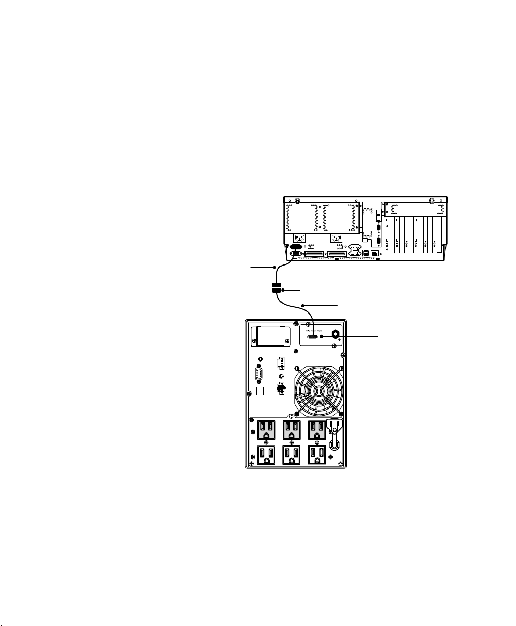
iSeries or AS/400 Interface Overview
To connect the UPS to an iSeries or AS/400 you need:
S An Eaton-supplied AS/400 interface cable (labeled 103004349-5501),
included with the UPS
Connect the cable as shown in Figure 9.
COMMUNICATION OPTIONS
AS/400 Interface Cable
(labeled 103004349-5501)
UPS
IBM iSeries Server
“J14” UPS Port
(location may
vary by model)
Figure 9. iSeries or AS/400 Interface on an E15
EATON 9130 (9910-E15/E16) UPS Installation Guide for IBM® Applications S 164201783 Rev 2
27

COMMUNICATION OPTIONS
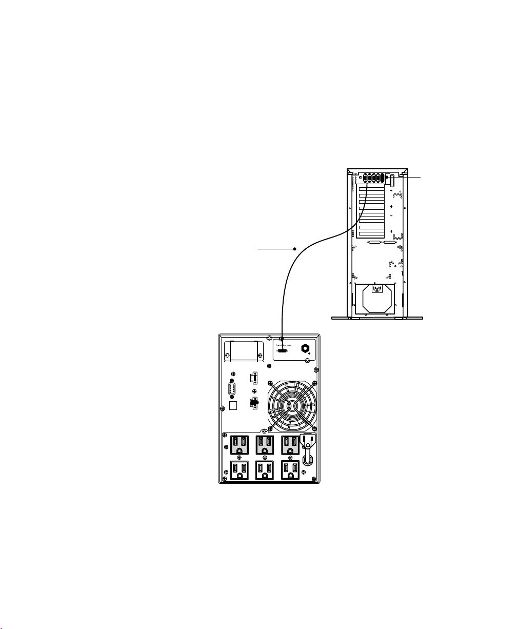
Serial (TTY) Interface Overview
To serially (TTY) connect the UPS to a System p, OpenPower, or other
system, you need:
S A Eaton-supplied serial interface cable (labeled 720-60258-00),
included with the UPS
S LanSafe Power Management Software from the Software Suite CD,
included with the UPS
For System p installations, you also need:
S An IBM-supplied 2-port Asynchronous EIA adapter (FC 5723) installed
on a System p server (a P-series UPS does not require an EIA
adapter)
S An IBM-supplied maintenance package 5200-05 for AIX 5.2L V5.2
(APAR IY66260); or the maintenance package 5300-01 for AIX 5.3L
V5.3 (APAR IY62267)
Follow the software installation instructions contained on the Software
Suite CD to install the LanSafe software. Connect the serial cable as
shown in Figure 10.
28
EATON 9130 (9910-E15/E16) UPS Installation Guide for IBM® Applications S 164201783 Rev 2
IBM System p
Server
COMMUNICATION OPTIONS
Serial Interface Cable
(labeled 720-60258-00)
UPS
2-Port Asynchronous
EIA Adapter
(FC 5723)
Figure 10. Serial (TTY) Interface for an E15 and System p Server
EATON 9130 (9910-E15/E16) UPS Installation Guide for IBM® Applications S 164201783 Rev 2
29
Chapter 4 Service and Support
F
l
In the United States and Canada, call 1-800-IBMSERV (1-800-426-7378).
In Europe, the Middle East, and Africa (EMEA); Latin America; or
Asia-Pacific, call the IBM office that services your account. Please have
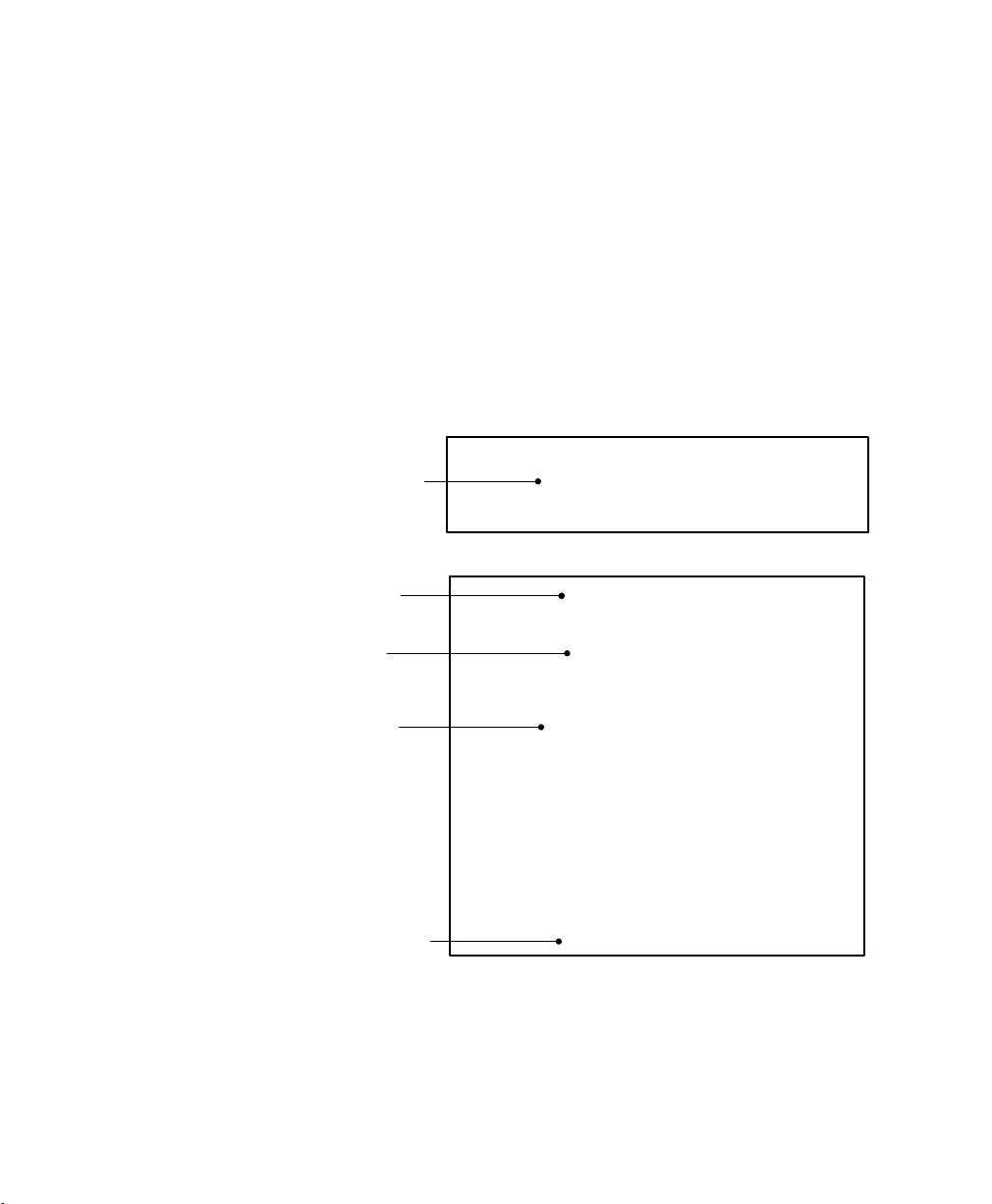
your serial, model, and part number ready when you call (see Figure 11).
For additional information, see the user's guide for the appropriate UPS
or Extended Battery Module (EBM).
Serial Number
Model Number
ront Panel Labe
IBM 9910-E15
(S) Serial Number: 991010R8AAA
991010R8AAA
Rear Panel Label
IBM 9910-E15
30
Part Number
Serial Number
Date Manufactured
Figure 11. Example of IBM Front and Rear Panel Labels
(P) IBM PN: 44V6738
P44V6738
P44V6738
(S) Serial Number: 991010R8AAA
S991010R8AAA
S991010R8AAA
(2P) EC L36358
2PL36358
2PL36358
(4L) Origin: China
4LCN
4LCN
Date of MFG: 20090123
Comments
We welcome your comments about this manual. Please send your
questions or suggestions for improvements to www.eaton.com/ibm.
EATON 9130 (9910-E15/E16) UPS Installation Guide for IBM® Applications S 164201783 Rev 2
 Loading...