

Eaton 93PM-L Series, 93PM-L 60-2, 93PM-L 60-1, 93PM-L 60-3, 93PM-L 60-3 (N+1) Installation And Operation Manual
...
Eaton® 93PM-L UPS
20 – 60 kW (208V) UPS
Installation and Operation Manual
p/n: P-164000711
Revision 03

IMPORTANT SAFETY INSTRUCTIONS SAVE THESE INSTRUCTIONS
!
This manual contains important instructions that you should follow during installation and maintenance
of the UPS and batteries. Please read all instructions before operating the equipment and save this
manual for future reference.
CONSIGNES DE SÉCURITÉ IMPORTANTES — CONSERVER CES INSTRUCTIONS
Ce manuel comporte des instructions importantes que vous êtes invité à suivre lors de toute
procédure d'installation et de maintenance des batteries et de l'onduleur. Veuillez consulter
entièrement ces instructions avant de faire fonctionner l'équipement et conserver ce manuel afin de
pouvoir vous y reporter ultérieurement.
IMPORTANT
To ensure you have the most up-to-date content and information for this product, please review the
latest manual revision on our website, www.eaton.com/93PM.
Eaton reserves the right to change specifications without prior notice. Eaton is a registered trademark of Eaton. National Electrical Code
and NEC are registered trademarks of National Fire Protection Association, Inc. ERIFLEX and FLEXIBAR are registered trademark of Erico
International Corporation. All other trademarks are property of their respective companies.
©Copyright 2017-2019 Eaton, Raleigh, NC, USA. All rights reserved. No part of this document may be reproduced in any way without the
express written approval of Eaton.

EATON
END-USER LICENSE AGREEMENT
IMPORTANT, READ CAREFULLY. THIS END USER LICENSE AGREEMENT (THE
“AGREEMENT”) IS A BINDING CONTRACT BETWEEN YOU, THE END-USER (THE
“LICENSEE”) AND EATON INTELLIGENT POWER LIMITED, IRELAND, OR ONE OF ITS
AFFILIATES (“EATON” OR “LICENSOR”). BY OPERATING THIS UNINTERRUPTIBLE
POWER SUPPLY (UPS) PRODUCT INCLUDING SOFTWARE EMBEDDED IN IT
(FIRMWARE), YOU, THE LICENSEE, ARE AGREEING TO BE BOUND BY THE TERMS,
CONDITIONS, AND LIMITATIONS OF THIS AGREEMENT. READ THE TERMS AND
CONDITIONS OF THIS AGREEMENT CAREFULLY BEFORE, INSTALLING OR OPERATING
THE PRODUCT. IF YOU DO NOT AGREE TO THE TERMS OF THIS AGREEMENT,
PROMPTLY RETURN THE UNUSED PRODUCT TO EATON.
1.0 DEFINITIONS
1.1 Documentation. “Documentation” means the user guides and manuals for the installation
and use of the UPS, whether made available over the internet, provided in CD-ROM, DVD,
hard copy or other form.
1.2 Firmware. “Firmware” means software programs that are embedded in the product for
which Licensee is granted a license hereunder, the Documentation therefore and, to the extent
available, Updates thereto. The Firmware is licensed hereunder in object code (machinereadable) form only except that certain software programs may include limited portions in
source code (human-readable) form.
1.3 Update. “Update” means a subsequent release of the Firmware, if and when developed by
Eaton. An Update does not include any release, new version, option, or future product, which
Eaton licenses separately.
2.0 FIRMWARE LICENSE
2.1 Ownership. Eaton or its third party licensors retains all title, copyright and other proprietary
rights in, and ownership of the Firmware regardless of the media upon which the original or any
copy may be recorded or xed.
2.2 License Grant. Eaton grants to Licensee a limited, revocable, non-exclusive, non-assignable
license to use the Firmware in conjunction with the operation of the product to which the Firmware
pertains or other products as described by Eaton in the Documentation. Licensee does not
acquire any rights, express or implied, other than those expressly granted in this Agreement.
2.3 Restrictions and Requirements. Licensee will not, nor will it permit others to, modify,
adapt, translate, reverse engineer, decompile, or disassemble the Firmware or any component
thereof (including the Documentation), or create derivative works based on the Firmware
(including the Documentation), except to the extent such foregoing restriction is prohibited by
applicable law or applicable open source license to, and only to, any open source software
component that is incorporated into the Firmware (if any). Copyright laws and international
treaties protect the Firmware, including the Documentation. Unauthorized copying of the
Firmware, the Documentation or any part thereof, is expressly prohibited. For avoidance of
doubt, Eaton does not grant Licensee a license to any of Eaton’s brands, logos, designs, trade
dress, service marks, trademarks, domain names or trade names, in whole or in part.
Licensee agrees to install or allow installation of all corrections of substantial defects, security
patches, minor bug xes and updates, including any enhancements, for the Firmware in
accordance with the instructions and as directed by Eaton.
2.4 Transfer and Assignment Restrictions. Licensee will not sell, resell, assign, lease,
sublicense, encumber, or otherwise transfer its interest in this Agreement or in the Firmware,
or the Documentation in whole or in part, or allow any other person or entity, including any
parent or subsidiary of Licensee or other subsidiary of Licensee’s parent, to copy, distribute,
or otherwise transfer the Firmware without the prior written consent of Eaton. Licensee may
transfer the Firmware directly to a third party only in connection with the sale of the Eaton
product in which it is installed.
3.0 TERMINATION
3.1 Termination. This Agreement and the license granted hereunder automatically terminates
if Licensee breaches any provision of this Agreement. Eaton may terminate this license at any
time with or without cause.
3.2 Effect of Termination. Immediately upon termination of this Agreement or the license
granted hereunder, Licensee will cease using the product. The parties’ rights and obligations
under the following sections of this Agreement will survive termination of this Agreement: Article
1.0, Section 2.1, Section 2.3, Section 2.4, Article 3.0, Article 4.0 and Article 5.0.
4.0 INFRINGEMENT AND WARRANTIES
4.1 Infringement. If Licensee learns of a threat, demand, allegation, or indication that the
UPS with its rmware infringes or misappropriates any third party intellectual property rights
(including but not limited to any patent, copyright, trademark, trade dress, or trade secret)
(“Intellectual Property Claim”), Licensee will notify Eaton promptly of such claim. Eaton may, in
its sole discretion, elect to assume sole control of the defense and settlement of said Intellectual
Property Claim and Licensee will provide reasonable information and assistance to Eaton for
the defense of such claim.
4.2 Disclaimer of Warranties. THE FIRMWARE IS PROVIDED “AS IS” WITHOUT
WARRANTY OF ANY KIND, . EATON DOES NOT WARRANT THAT THE FIRMWARE
WILL BE ERROR-FREE OR SECURE FROM UNAUTHORIZED ACCESS. THE LICENSEE
EXPRESSLY ACKNOWLEDGES THAT TO THE EXTENT PERMITTED BY APPLICABLE
LAW, THE USE OF THE PRODUCT IS AT LICENSEE’S SOLE RISK.
5.0 GENERAL PROVISIONS
5.1 Update Policy. Eaton may from time to time, but has no obligation to, create Updates of
the Firmware or components thereof.
5.2 Limitation on Liability. NOTWITHSTANDING ANY PROVISION OF THIS AGREEMENT
TO THE CONTRARY, LICENSEE EXPRESSLY UNDERSTANDS AND AGREES THAT
EATON, ITS AFFILIATES, AND ITS LICENSORS, WILL NOT BE LIABLE FOR: (A) ANY
DIRECT, INDIRECT, INCIDENTAL, SPECIAL, CONSEQUENTIAL OR EXEMPLARY
DAMAGES WHICH MAY BE INCURRED BY LICENSEE OR ANY THIRD PARTY,
HOWEVER CAUSED AND UNDER ANY THEORY OF LIABILITY. THIS WILL INCLUDE,
BUT NOT BE LIMITED TO, ANY LOSS OF PROFIT (WHETHER INCURRED DIRECTLY OR
INDIRECTLY), ANY LOSS OF GOODWILL OR BUSINESS REPUTATION, ANY LOSS OF
DATA SUFFERED, COST OF PROCUREMENT OF SUBSTITUTE GOODS OR SERVICES,
OR OTHER INTANGIBLE LOSS; (B) ANY LOSS OR DAMAGE WHICH MAY BE INCURRED
BY LICENSEE OR ANY THIRD PARTY. THESE LIMITATIONS ON EATON’S LIABILITY WILL
APPLY WHETHER OR NOT EATON HAS BEEN ADVISED OF OR SHOULD HAVE BEEN
AWARE OF THE POSSIBILITY OF ANY SUCH LOSSES ARISING.
TO THE EXTENT PERMITTED BY LAW, THE TOTAL LIABILITY OF EATON, ITS AFFILIATES,
AND ITS LICENSORS, FOR ANY CLAIMS UNDER THESE TERMS, INCLUDING FOR ANY
IMPLIED WARRANTIES, IS LIMITED TO THE AMOUNT PAID FOR THE UPS.
THIS SECTION 5.2 STATES EATON’S ENTIRE LIABILITY AND LICENSEE’S SOLE AND
EXCLUSIVE REMEDY UNDER THIS AGREEMENT, AND IS SUBJECT TO ALL LIMITATIONS
STATED IN SECTION 4.2.
5.3 Notices. All notices required to be sent hereunder will be in writing and will be deemed to
have been given when mailed by rst class mail to the address shown below:
LICENSE NOTICES:
Eaton Intelligent Power Limited
Eaton House,
30 Pembroke Road,
Dublin 4,
D04 Y0C2,
Ireland
5.4 Severability. If any provision of this Agreement is held to be invalid or unenforceable, the
remaining provisions of this Agreement will remain in full force.
5.5 Waiver. The waiver by either party of any default or breach of this Agreement will not
constitute a waiver of any other or subsequent default or breach. Failure to enforce or delay in
enforcing any provision of this Agreement will not constitute a waiver of any rights under any
provisions of this Agreement.
5.6 Entire Agreement. This Agreement constitutes the complete agreement between the
parties and supersedes all prior or contemporaneous agreements or representations, written
or oral, concerning the subject matter of this Agreement. This Agreement may not be modied
or amended except in a writing specically referencing this Agreement and signed by a duly
authorized representative of each party. No other act, document, usage or custom will be
deemed to amend or modify this Agreement. The Firmware, or portions thereof, may also
be subject to additional paper or electronic license agreements. In such cases, the terms of
this Agreement will be supplemental to those in the additional agreements, to the extent not
inconsistent with the additional agreements. If a copy of this Agreement in a language other
than English is included with the Firmware or Documentation, it is included for convenience and
the English language version of this Agreement will control.
5.7 Heirs, Successors, and Assigns. Each and all of the covenants, terms, provisions
and agreements herein contained will be binding upon and inure to the benet of the parties
hereto and, to the extent expressly permitted by this Agreement, their respective heirs, legal
representatives, successors and assigns.
5.8 Export Restrictions. Licensee agrees to comply fully with all relevant export laws and
regulations of the United States and all other countries in the world (the “Export Laws”) to
assure that neither the Firmware nor any direct product thereof are (I) exported, directly or
indirectly, in violation of Export Laws; or (ii) are intended to be used for any purposes prohibited
by the Export Laws. Without limiting the foregoing, Licensee will not export or re-export the
Firmware: (i) to any country to which the U.S. has embargoed or restricted the export of
goods or services (see http://www.treasury.gov/resource-center/sanctions/Programs/Pages/
Programs.aspx), or to any national of any such country, wherever located, who intends to
transmit or transport the Firmware back to such country; (ii) to any end user who Licensee
knows or has reason to know will utilize the Firmware in the design, development or production
of nuclear, chemical or biological weapons; or (iii) to any end-user who has been prohibited
from participating in U.S. export transactions by any federal agency of the U.S. government.
5.9 U.S. Government Restricted Rights. The Firmware is a “commercial item” as that term
is dened at 48 C.F.R. § 2.101, consisting of “commercial computer software” and “commercial
computer software documentation”, as such terms are used in 48 C.F.R. § 12.212, and is
provided to the U.S. Government only as a commercial end item. Consistent with 48 C.F.R.
§ 12.212 and 48 C.F.R. §§ 227.7202-1 through 227.7202-4, all U.S. Government End Users
acquire the Firmware with only those rights set forth herein. Contractor/manufacturer is Eaton
Corporation, 1000 Eaton Boulevard, Cleveland, Ohio 44122.
5.10 Third Party Intellectual Property Rights. The Firmware may contain components
(including open source software components) that are owned by third parties (“Third Party
Licensors”) and are provided with, incorporated into, or embedded in, the Firmware pursuant to
license arrangements between Eaton and such third parties. Third Party Licensor components
in the Firmware are not licensed or warranted under the terms of this document, but are instead
subject to the Third Party Licensors’ license agreements. Licensee will not modify, delete, or
obfuscate any copyright or other proprietary rights notices of Third Party Licensors contained
in the Firmware.
5.11 Indemnity. Licensee shall defend, indemnify and hold Eaton and its ofcers, directors,
employees, and agents harmless from and against all losses, damages, liabilities, claims,
actions, and associated costs and expenses (including reasonable attorneys’ fees and expenses)
by reason of injury or death to any person or damage to any tangible or intangible property arising
or resulting from the negligence or willful misconduct of the Licensee, its employees, contractors,
or agents, in connection with Licensee’s use of Firmware and Documentation.
Licensee shall be responsible for any breach of this Agreement by its ofcers, directors,
employees, contractors, or agents. Licensee shall defend, indemnify, and hold Eaton and
its ofcers, directors, employees, and agents harmless from and against any and all losses,
damages, liabilities, claims, actions, and associated costs and expenses (including reasonable
attorneys’ fees and expenses) arising out of or in connection with any breach of this Agreement.
5.12 Open Source Software. The Firmware may contain certain components owned by
Eaton that are provided with, incorporated into, linked to, or embedded in the Firmware that are
subject to third party open source licenses (“Eaton Open Source Components”). Eaton Open
Source Components are subject to the open source licenses corresponding to the particular
software component. To the extent there are any conicts between the terms of this Agreement
and any open source license corresponding to Eaton Open Source Components or additional
obligations by such open sources license that are not set forth in this Agreement, the terms of
the open source license will control.
5.13 Condentiality. Licensee acknowledges that condential aspects of the Firmware
(including any proprietary source code) are a trade secret of Eaton, the disclosure of which
would cause substantial harm to Eaton that could not be remedied by the payment of damages
alone and such condential aspects of the Firmware shall not be disclosed to third parties
without the prior written consent of Eaton. Accordingly, Eaton will be entitled to preliminary and
permanent injunctive and other equitable relief for any breach of this Section 5.13.
5.14 Note on JAVA Support. The Firmware may contain support for programs written in JAVA.
JAVA technology is not fault tolerant and is not designed, manufactured, or intended for use or
resale as online control equipment in hazardous environments requiring fail-safe performance,
such as in the operation of nuclear facilities, aircraft navigation or communications systems, air
trafc control, direct life support machines, or weapons systems, in which the failure of JAVA
technology could lead directly to death, personal injury, or severe physical or environmental
damage. EATON DISCLAIMS ALL DAMAGES INCLUDING DIRECT, INDIRECT AND
CONSEQUENTIAL DAMAGES RELATING TO THE FAILURE OF ANY SOFTWARE
INCLUDING JAVA PROGRAMS AND/OR JAVA TECHNOLOGY.
5.15 Governing Law. This Agreement will be interpreted and enforced in accordance with the
laws of Ireland, without regard to choice of law principles. Any claim or suit with respect to this
Agreement shall be brought in the Courts of Ireland, unless mandatory law imposes otherwise.
Eaton EULA
P-110000654-001 Revised: December 21st, 2018


TTaabbllee ooff CCoonntteennttss
11 IInnttrroodduuccttiioonn .................................................................................................................................................................................................................................................................................................... 11
1.1 UPS Standard Features ............. ... .......... ... ... ....... ... .......... ... ... .......... ............. ... .......... ... ... ....... ... .......... ... ... .. 1
1.1.1 Installation Features ... .......... ... ............. ... ....... ... ... .......... ... .......... ... ... ....... ... ............. ... ....... ... ... .......... ... 1
1.1.2 Control Panel . .......... ... ............. .......... ... ... .......... ... .......... ... .......... ... ............. .......... ... ... .......... ... .......... . 3
1.1.3 Customer Interface . ....... ... ... ... ....... ... .......... ... ... ....... ... ... .......... ... .......... ... ... ....... ... ............. ... .......... ... ...3
1.1.4 Energy Saver System Mode. .......... ... ... ....... ... ............. ... .......... ... .......... ... .......... ... ... .......... ............. ... ..... 3
1.1.5 Internal Redundancy.... .......... ... ... .......... ............. ... .......... ... ............. .......... ... ... .......... ... .......... ... .......... .. 4
1.1.6 Advanced Battery Management. ............. ... ....... ... ... .......... ... .......... ... ... ....... ... ............. ... ....... ... ... .......... ... 4
1.2 Options and Accessories. ... .......... ... ... ....... ... ............. ... ....... ... ... .......... ... .......... ... ... ....... ... ............. ... .......... .. 4
1.2.1 Integrated Battery Cabinet .......... ... ... ....... ... ............. ... ....... ... ... ... ....... ... .......... ... ... ....... ... ... .......... ... ........ 4
1.2.2 Sidecar Integrated Accessory Cabinet-Bypass.. ... .......... ... .......... ... .......... ... ... .......... .......... ... ... .......... ... ....... 5
1.2.3 Top Entry Wiring Sidecar .... ....... ... ... .......... ... ....... ... ... .......... ... ............. ... ....... ... ... .......... ... ....... ... ... ... ...... 5
1.2.4 Integrated Accessory Cabinet-Power Distribution .... .......... ... .......... ... .......... ... ... ....... ... ............. ... .......... ... ...5
1.2.5 Parallel System .... .......... ... ....... ... ... ... ....... ... ............. ... ....... ... ... .......... ... ....... ... ... ... ....... ... ............. ... ..... 5
1.2.6 Monitoring and Communication .............. ... .......... ... ... ....... ... .......... ... ... ....... ... ............. ... .......... ... ... ....... ... 5
1.2.7 Additional Output Surge Protection.. ... ....... ... ............. ... .......... ... ... ....... ... .......... ... ... ....... ... ... .......... ... ........ 6
1.3 Battery System . ... ....... ... ... .......... ... ....... ... ... .......... ... ............. ... ....... ... ... .......... ... ....... ... ... .......... ... ............. . 6
1.3.1 Battery Configurations . ....... ... ... .......... ... ............. ... ....... ... ... .......... ... .......... ... ... ....... ... ............. ... ....... ... .. 6
1.3.2 Optional Thermal Sensor .... ....... ... ... .......... ... ....... ... ... ... ....... ... ............. ... ....... ... ... .......... ... .......... ... ... ...... 6
1.4 Basic System Configurations.. ... .......... ... .......... ... .......... ... ... .......... ............. ... .......... ... ............. .......... ... ... ......6
1.5 Using This Manual ... ... .......... ... .......... ... ... ....... ... ............. ... .......... ... .......... ... .......... ... ... ....... ... ............. ... ..... 7
1.6 Conventions Used in This Manual ...... .......... ... ... .......... ... .......... ... .......... ... ............. ... ....... ... ... .......... ... .......... . 7
1.7 Symbols, Controls, and Indicators ... ... .......... ... ... .......... ............. ... .......... ... ............. .......... ... ... .......... ... .......... . 8
1.8 For More Information .. ... .......... ... .......... ... ... .......... .......... ... ... .......... ... ............. .......... ... ... .......... ... ....... ... ... .. 8
1.9 Getting Help.. ... ....... ... ... .......... ... .......... ... .......... ... ............. ... ....... ... ... .......... ... .......... ... .......... ... ............. ... . 9
1.10 Equipment Registration... ... .......... ... ............. .......... ... ... .......... ... ....... ... ... .......... ... ............. ... ....... ... ... .......... 9
22 SSaaffeettyy WWaarrnniinnggss.................................................................................................................................................................................................................................................................................... 1111
33 UUPPSS IInnssttaallllaattiioonn PPllaann aanndd UUnnppaacckkiinngg ........................................................................................................................................................................................................................ 1133
3.1 Creating an Installation Plan .... .......... ... ... ....... ... ............. ... ....... ... ... .......... ... .......... ... ... ....... ... ... .......... ... ...... 13
3.2 Preparing the Site .... ... ....... ... .......... ... ... ....... ... ............. ... ....... ... ... ... ....... ... .......... ... ... ....... ... ... .......... ... ...... 13
3.2.1 Environmental and Installation Considerations .. ... ....... ... ... .......... ... .......... ... ... ....... ... ............. ... ....... ... ... ... . 13
3.3 UPS System Power Wiring Preparation .... .......... ... .......... ... ... ....... ... ............. ... .......... ... .......... ... .......... ... ... .... 33
3.4 External Parallel UPS System Power Wiring Preparation .... .......... ... .......... ... .......... ... ............. ... ....... ... ... .......... . 35
3.5 UPS System Interface Wiring Preparation ... ....... ... ... .......... ... .......... ... ... ....... ... ... .......... ... ....... ... ... .......... ... ..... 50
3.6 Inspecting and Unpacking the UPS Cabinet . ... ....... ... ... .......... ... .......... ... ... ....... ... ............. ... ....... ... ... .......... ... .. 51
44 UUPPSS SSyysstteemm IInnssttaallllaattiioonn.............................................................................................................................................................................................................................................................. 5555
4.1 Preliminary Installation Information. ... ....... ... ... .......... ... .......... ... ... ....... ... ............. ... .......... ... .......... ... .......... ... 55
4.2 Unloading the UPS Cabinet from the Pallet.... ... .......... .......... ... ... .......... ... .......... ... .......... ... ... .......... ... ....... ... ... 55
Eaton 93PM-L 20 – 60 kW (208V) UPS Installation and Operation Manual P-164000711—Rev 03 v

Table of Contents
4.3 Integrated Battery Cabinet Installation.. ... .......... ... ... ....... ... ............. ... ....... ... ... .......... ... .......... ... ... ....... ... ........ 60
4.4 External AC Power Wiring Installation .... .......... ... ............. .......... ... ... .......... ... .......... ... .......... ... ... .......... ......... 60
4.4.1 Standalone UPS or UPS with Top Entry Sidecar (No Breakers). .... ....... ... ............. ... ....... ... ... .......... ... ....... ... ... 61
4.4.2 UPS with 2-Breaker Sidecar (MBP and MIS) .... ....... ... ... .......... ... ....... ... ... ... ....... ... ............. ... ....... ... ... ........ 67
4.4.3 UPS with 3-Breaker Sidecar (BIB, MBP and MIS).. ....... ... ... .......... ... .......... ... .......... ... ............. ... ....... ... ... .... 70
4.4.4 UPS with 4 -Breaker Sidecar (RIB, BIB, MBP and MIS). .......... ... .......... ... ... ....... ... ............. ... ....... ... ... ... ....... . 72
4.5 Battery Power Wiring ... ... .......... ... .......... ... .......... ... ............. ... ....... ... ... .......... ... .......... ... .......... ... ............. .. 74
4.6 Installing Interface Connections ... ............. .......... ... ... .......... ... ....... ... ... .......... ... ............. ... ....... ... ... .......... ... .. 75
4.6.1 Installing Building Alarm and Relay Contact Connections.. ... ....... ... ............. ... ....... ... ... .......... ... ....... ... ... ... .... 75
4.6.2 Sidecar MIS and RIB Breaker Monitoring Connections.. .......... ... .......... ... .......... ... ... .......... ... .......... ... .......... 81
4.6.3 Installing Battery Detect Interface Connections. .......... ... ... .......... ... .......... ... .......... ... ............. ... ....... ... ... .... 83
4.6.4 Installing Battery Shunt Trip and Battery Aux Interface Connections .. ... ....... ... ... .......... ... ....... ... ... ... ....... ... ..... 84
4.6.5 Bypass Shunt Trip Connections .. ... .......... ... .......... ... .......... ... ............. ... ....... ... ... .......... ... .......... ... .......... 86
4.6.6 Generator Interface Connections.. ... ....... ... ... .......... ... .......... ... .......... ... ............. ... ....... ... ... .......... ... ......... 86
4.6.7 External Parallel CAN Control Wiring and Connections . .......... ... .......... ... .......... ... ............. ... ....... ... ... .......... . 87
4.6.8 External Parallel Pull Chain Control Wiring and Connections . .......... ... .......... ... ... ....... ... ............. ... ....... ... ... .... 90
4.6.9 Installing Minislot Interface Connections.. ... ....... ... ............. ... ....... ... ... ... ....... ... .......... ... ... ....... ... ............. .. 93
4.7 Installing a REPO Switch ... ....... ... ... .......... ... .......... ... ... ....... ... ............. ... ....... ... ... .......... ... .......... ... ... ....... ... . 94
4.8 Initial Startup ..... .......... ... ... .......... ............. ... .......... ... ... .......... .......... ... ... .......... ... .......... ... .......... ... ... ........ 97
4.9 Completing the Installation Checklist ... ... .......... ... ... ....... ... ............. ... .......... ... ... ....... ... .......... ... ... ....... ... ........ 97
4.10 Installation Checklist... ... .......... ... .......... ... .......... ... ............. .......... ... ... .......... ... .......... ... .......... ... ............. .. 98
55 UUnnddeerrssttaannddiinngg UUPPSS OOppeerraattiioonn ..........................................................................................................................................................................................................................................110011
5.1 UPS System Overview .. ... ....... ... ... .......... ... .......... ... ... ....... ... ............. ... ....... ... ... .......... ... .......... ... ... ....... .. 101
5.2 Single UPS.. ............. ... ....... ... ... .......... ... .......... ... ... ....... ... ... .......... ... ....... ... ... .......... ... ............. ... ....... ... .. 102
5.2.1 Modes.... ....... ... ... ... ....... ... ............. ... ....... ... ... .......... ... ....... ... ... ... ....... ... ............. ... ....... ... ... .......... ... 102
5.2.2 Energy Saver System Mode. .......... ... ... ....... ... ............. ... .......... ... .......... ... .......... ... ... .......... ............. ... . 102
5.2.3 Normal Mode.... .......... ... .......... ... ... ....... ... ............. ... ....... ... ... .......... ... .......... ... ... ....... ... ... .......... ... .... 103
5.2.4 Bypass Mode.... ... ....... ... .......... ... ... ....... ... ............. ... .......... ... ... ....... ... .......... ... ... ....... ... ... .......... ... .... 104
5.2.5 Battery Mode.... .......... ... .......... ... ... ....... ... ............. ... ....... ... ... .......... ... .......... ... ... ....... ... ... .......... ... .... 105
5.3 Single UPS Unit System Oneline Configurations... .......... ... ... ....... ... ............. ... .......... ... ... ....... ... .......... ... ... ..... 107
66 UUPPSS OOppeerraattiinngg IInnssttrruuccttiioonnss ..................................................................................................................................................................................................................................................111111
6.1 UPS Controls and Indicators.. ... .......... ... .......... ... ... ....... ... ............. ... ....... ... ... ... ....... ... .......... ... ... ....... ... ...... 111
6.2 Using the Control Panel .. ... .......... ... ... ....... ... ............. ... ....... ... ... .......... ... .......... ... ... ....... ... ............. ... ........ 112
6.2.1 Status Indicators.... .......... ... .......... ... .......... ... ... .......... ... ....... ... ... .......... ... ............. .......... ... ... .......... ... 112
6.2.2 System Events... .......... ... .......... ... .......... ... ... ....... ... ............. ... .......... ... ... ....... ... .......... ... ... .......... ...... 113
6.2.3 Using the LCD Touch Screen... ... .......... ... .......... ... .......... ... ... ....... ... ............. ... .......... ... .......... ... .......... . 113
6.2.4 Using the Menu.. .......... ... ............. ... ....... ... ... .......... ... .......... ... ... ....... ... ... .......... ... ....... ... ... .......... ... ... 114
6.2.5 Mimic Screen .... .......... ... .......... ... .......... ... ... ....... ... ............. ... .......... ... ... ....... ... .......... ... ... .......... ...... 115
6.2.6 Display Menu Operation. ... ....... ... ............. ... ....... ... ... .......... ... .......... ... ... ....... ... ............. ... ....... ... ... ...... 116
6.2.7 Sign In... .......... ... ............. .......... ... ... .......... ... .......... ... .......... ... ............. .......... ... ... .......... ... .......... ... . 121
vi Eaton 93PM-L 20 – 60 kW (208V) UPS Installation and Operation Manual P-164000711—Rev 03

Table of Contents
6.2.8 System Controls... .......... ... .......... ... ... ....... ... ............. ... .......... ... .......... ... .......... ... ... ....... ... ............. ... . 123
6.3 Single UPS Operation .... .......... ... ... ....... ... .......... ... ... .......... ... .......... ... .......... ... ... ....... ... ............. ... .......... .. 127
6.3.1 Starting the UPS in Double Conversion Mode ..... .......... ... .......... ... ... ....... ... ... .......... ... ....... ... ... ... ....... ... ... 127
6.3.2 Starting the UPS in Bypass Mode............ ... ....... ... ... .......... ... .......... ... .......... ... ............. ... ....... ... ... ......... 127
6.3.3 Starting the UPMs .. ....... ... ... ... ....... ... .......... ... ... ....... ... ... .......... ... ....... ... ... ... ....... ... ............. ... ....... ... .. 128
6.3.4 Starting a Single UPM. .......... ... .......... ... .......... ... ... .......... ............. ... .......... ... .......... ... .......... ... ... ......... 128
6.3.5 Transfer from Double Conversion to Bypass Mode .... ............. .......... ... ... .......... ... ....... ... ... .......... ... .......... 128
6.3.6 Transfer from Bypass to Double Conversion Mode .... ............. .......... ... ... .......... ... ....... ... ... .......... ... .......... 129
6.3.7 Transfer from ESS Mode to Double Conversion Mode.. .......... ... .......... ... .......... ... ... .......... ... .......... ... ........ 129
6.3.8 Transfer from Double Conversion Mode to ESS Mode.. .......... ... .......... ... .......... ... ... .......... ... .......... ... ........ 129
6.3.9 Transfer from Double Conversion to Bypass Mode and Shut Down UPMs ... .......... .......... ... ... .......... ... .......... 129
6.3.10 Single UPM Shutdown .... .......... ............. ... .......... ... .......... ... .......... ... ... .......... ............. ... .......... ... ...... 130
6.3.11 Single UPM Restart .... ....... ... .......... ... ... .......... ............. ... .......... ... ... ....... ... .......... ... ... .......... ............. 130
6.3.12 UPS and Critical Load Shutdown ... ... ....... ... ............. ... .......... ... ... ....... ... .......... ... ... ....... ... ... .......... ... .... 130
6.3.13 Charger Control ..... .......... ... ... ....... ... ... .......... ... ....... ... ... ... ....... ... ............. ... ....... ... ... .......... ... ....... ... . 131
6.3.14 Battery Test.. ....... ... ... .......... ... ............. ... ....... ... ... .......... ... ....... ... ... ... ....... ... ............. ... ....... ... ... ...... 131
6.3.15 Using the UPS LOAD OFF Command . ....... ... ... ... ....... ... .......... ... ... ....... ... ... .......... ... .......... ... ... ....... ... ... 131
6.3.16 Using the Remote Emergency Power-off Switch .... ....... ... ... .......... ... ............. ... ....... ... ... .......... ... ....... ... . 132
6.4 Multiple External Parallel System Operation .... ....... ... ... .......... ... ............. ... ....... ... ... .......... ... .......... ... ... ....... .. 133
6.4.1 Starting the Parallel System in Double Conversion Mode.............. ... .......... ... ... .......... .......... ... ... .......... ... ... 133
6.4.2 Starting the Parallel System in Bypass Mode ............... ... ....... ... ... .......... ... .......... ... ... ....... ... ... .......... ... .... 134
6.4.3 Starting the Parallel System UPMs ........... ... .......... ... ... ....... ... ............. ... ....... ... ... ... ....... ... .......... ... ... ..... 134
6.4.4 Starting a Single UPM. .......... ... .......... ... .......... ... ... .......... ............. ... .......... ... .......... ... .......... ... ... ......... 135
6.4.5 Transfer from Double Conversion to Bypass Mode .... ............. .......... ... ... .......... ... ....... ... ... .......... ... .......... 135
6.4.6 Transfer from Bypass to Double Conversion Mode .... ............. .......... ... ... .......... ... ....... ... ... .......... ... .......... 135
6.4.7 Transfer from ESS Mode to Double Conversion Mode.. .......... ... .......... ... .......... ... ... .......... ... .......... ... ........ 136
6.4.8 Transfer from Double Conversion Mode to ESS Mode.. .......... ... .......... ... .......... ... ... .......... ... .......... ... ........ 136
6.4.9 Transfer from Double Conversion to Bypass Mode and Shutdown all UPMs.. ... .......... ............. ... .......... ... ...... 136
6.4.10 Single UPM Shutdown .... .......... ............. ... .......... ... .......... ... .......... ... ... .......... ............. ... .......... ... ...... 137
6.4.11 Single UPM Restart .... ....... ... .......... ... ... .......... ............. ... .......... ... ... ....... ... .......... ... ... .......... ............. 137
6.4.12 Single UPS Shutdown .............. ... ....... ... ... .......... ... .......... ... ... ....... ... ............. ... .......... ... ... ....... ... ....... 137
6.4.13 Single UPS Restart ........... ... ... ....... ... ... .......... ... ....... ... ... ... ....... ... ............. ... ....... ... ... .......... ... ....... ... . 137
6.4.14 Parallel System and Critical Load Shutdown.. .......... ............. ... .......... ... ............. .......... ... ... .......... ... ....... 138
6.4.15 Charger Control ..... .......... ... ... ....... ... ... .......... ... ....... ... ... ... ....... ... ............. ... ....... ... ... .......... ... ....... ... . 138
6.4.16 Battery Test.. ....... ... ... .......... ... ............. ... ....... ... ... .......... ... ....... ... ... ... ....... ... ............. ... ....... ... ... ...... 139
6.4.17 Using the LOAD OFF Command... ... .......... ... .......... ... ... ....... ... ............. ... .......... ... .......... ... .......... ... ... .. 139
6.4.18 Using the Remote Emergency Power-off Switch .... ....... ... ... .......... ... ............. ... ....... ... ... .......... ... ....... ... . 140
77 CCoommmmuunniiccaattiioonn ....................................................................................................................................................................................................................................................................................114411
7.1 Minislot Cards.... .......... ... ... .......... ............. ... .......... ... ... .......... .......... ... ... .......... ... .......... ... .......... ... ... ...... 141
7.2 Building Alarm Monitoring ... ... .......... ... .......... ... ............. ... ....... ... ... .......... ... .......... ... ... ....... ... ... .......... ... .... 141
7.3 General Purpose Relay Contact .. ... .......... ... ... .......... .......... ... ... .......... ... ............. .......... ... ... .......... ... ....... ... . 142
Eaton 93PM-L 20 – 60 kW (208V) UPS Installation and Operation Manual P-164000711—Rev 03 vii

Table of Contents
7.4 PredictPulse Remote Monitoring and Management Service... ............. ... .......... ... ... ....... ... .......... ... ... ....... ... ...... 142
7.4.1 PredictPulse Service Features ... ............. .......... ... ... .......... ... .......... ... .......... ... ............. ... ....... ... ... ......... 142
7.4.2 Installing PredictPulse.... .......... ... ............. .......... ... ... .......... ... ....... ... ... .......... ... ............. ... ....... ... ... ...... 143
88 UUPPSS MMaaiinntteennaannccee..............................................................................................................................................................................................................................................................................114455
8.1 Important Safety Instructions .... .......... ... ............. .......... ... ... .......... ... .......... ... .......... ... ............. ... ....... ... ... .. 145
8.2 Performing Preventive Maintenance ... ....... ... ... ... ....... ... ............. ... ....... ... ... .......... ... .......... ... ... ....... ... .......... 145
8.2.1 DAILY Maintenance ..... ............. .......... ... ... .......... ... .......... ... .......... ... ............. .......... ... ... .......... ... ....... 146
8.2.2 MONTHLY Maintenance . ....... ... ... ... ....... ... .......... ... ... ....... ... ............. ... .......... ... ... ....... ... .......... ... ... ..... 146
8.2.3 PERIODIC Maintenance.. .......... ... ... ....... ... .......... ... ... .......... ............. ... .......... ... ... ....... ... .......... ... ... ..... 147
8.2.4 ANNUAL Maintenance.... .......... ... ... ....... ... .......... ... ... .......... ............. ... .......... ... ... ....... ... .......... ... ... ..... 147
8.2.5 BATTERY Maintenance... .......... ... ... .......... .......... ... ... .......... ... ............. .......... ... ... .......... ... ....... ... ... ..... 147
8.3 Installing Batteries . .......... ... ... .......... ... .......... ... .......... ... ............. ... ....... ... ... .......... ... .......... ... .......... ... ...... 147
8.4 Recycling the Used Battery or UPS... .......... ... .......... ... ... .......... ............. ... .......... ... ............. .......... ... ... ......... 148
8.5 Maintenance Training . ... ....... ... ... .......... ... .......... ... ... ....... ... ... .......... ... ....... ... ... .......... ... ............. ... ....... ... .. 148
99 PPrroodduucctt SSppeecciiffiiccaattiioonnss ..............................................................................................................................................................................................................................................................114499
9.1 Models... ............. ... ....... ... ... .......... ... .......... ... ... ....... ... ............. ... ....... ... ... ... ....... ... .......... ... ... ....... ... ...... 149
9.2 Specifications ..... ............. ... ....... ... ... ... ....... ... .......... ... ... ....... ... ............. ... ....... ... ... ... ....... ... .......... ... ... ..... 149
9.2.1 UPS Input .... .......... ... .......... ... ... ....... ... ............. ... .......... ... .......... ... .......... ... ... ....... ... ............. ... ........ 149
9.2.2 UPS Output.. .......... ... ....... ... ... ... ....... ... ............. ... ....... ... ... .......... ... .......... ... ... ....... ... ............. ... ....... . 149
9.2.3 UPS Environmental . ....... ... ... .......... ... .......... ... ... ....... ... ... .......... ... ....... ... ... ... ....... ... ............. ... ....... ... .. 150
1100 WWaarrrraannttyy....................................................................................................................................................................................................................................................................................................115511
viii Eaton 93PM-L 20 – 60 kW (208V) UPS Installation and Operation Manual P-164000711—Rev 03

LLiisstt ooff FFiigguurreess
Figure 1. Eaton 93PM-L UPS (60 kW, Four-Wire) ... ....... ... ............. ... ....... ... ... .......... ... ....... ... ... ... ....... ... ............. . 2
Figure 2. Eaton 93PM-L UPS (60 kW, Four-Wire) with Top Entry Wiring Sidecar ....... ... ... .......... ... .......... ... ... ....... ... ...2
Figure 3. Eaton 93PM-L UPS (60 kW, Four-Wire) with Bypass Sidecar (2, 3 or 4 Breaker SIAC-B).. .......... ............. ... ..... 3
Figure 4. UPS Cabinet Dimensions (Front and Right Side Views).......... ... ... .......... ... .......... ... .......... ... ... .......... ..... 18
Figure 5. UPS Cabinet Dimensions (Top and Bottom Views) .... ....... ... ... .......... ... .......... ... .......... ... ... .......... ... ...... 19
Figure 6. UPS Cabinet Rear Floor Mounting Bracket Mounting Dimensions ............. ... .......... ... ... ....... ... .......... ... ... 20
Figure 7. UPS Cabinet Floor Mounting Bracket Dimensions (Top Views)... ....... ... ... .......... ... .......... ... ... ....... ... ........ 21
Figure 8. UPS with Left or Right-Mounted Top Entry Sidecar Dimensions (Front Views)............ ... .......... ... ............. .. 22
Figure 9. UPS with Left or Right-Mounted Top Entry Sidecar Dimensions (Top and Bottom Views) ........... ... ... .......... . 23
Figure 10. UPS with Left or Right-Mounted Bypass Sidecar (SIAC-B) Dimensions (Front Views). .......... ... .......... ... ... .... 24
Figure 11. UPS with Left or Right-Mounted Bypass Sidecar (SIAC-B) Dimensions (Top and Bottom Views) ............. ... ... 25
Figure 12. UPS Cabinet Center of Gravity ... .......... ... ....... ... ... ... ....... ... ............. ... ....... ... ... .......... ... .......... ... ... .... 26
Figure 13. UPS with Left or Right-Mounted Top Entry Wiring Sidecar Center of Gravity. .......... ... ....... ... ... .......... ... ..... 27
Figure 14. UPS with Left or Right-Mounted SIAC-B Center of Gravity ... .......... ... .......... ... .......... ... ............. .......... ... 29
Figure 15. Remote EPO Switch Dimensions .. .......... ... .......... ... ... .......... .......... ... ... .......... ... ............. .......... ... ... . 33
Figure 16. 93PM-L External Parallel Wire Length. .......... ... .......... ... ... ....... ... ............. ... .......... ... .......... ... .......... ... 35
Figure 17. UPS Cabinet as Shipped on Pallet .......... ... ............. ... ....... ... ... .......... ... ....... ... ... .......... ... ............. ... ... 52
Figure 18. UPS Cabinet with Left or Right-Mounted Top Entry Wiring Sidecar as Shipped on Pallet............. ... ....... ... ... . 52
Figure 19. UPS Cabinet with Left or Right-Mounted Sidecar as Shipped on Pallet.. .......... ... .......... ... ... ....... ... ............ 53
Figure 20. Removing the UPS Pallet Skids and Supports ........... ... .......... ... ... ....... ... ............. ... .......... ... .......... ... .. 56
Figure 21. Removing the Top Entry Sidecar Pallet Skids and Supports ............... ... .......... ... ... ....... ... .......... ... ... ....... 57
Figure 22. Removing the Bypass Sidecar (SIAC-B) Pallet Skids and Supports .... ... ....... ... .......... ... ... ....... ... ............. .. 57
Figure 23. Removing the Sidecar Rear Shipping Bracket – UPS with Right-Mounted Sidecar ... .......... ... ... .......... ......... 59
Figure 24. UPS Conduit and Wire Entry Locations ... .......... ... .......... ... ... .......... ............. ... .......... ... ... ....... ... ......... 62
Figure 25. UPS with Top Entry Sidecar Conduit and Wire Entry Locations........... ... ....... ... ... .......... ... .......... ... ... ....... 63
Figure 26. UPS Inter-Cabinet Wiring Access Location.. ............. .......... ... ... .......... ... ....... ... ... .......... ... ............. ...... 64
Figure 27. Power Terminal Locations... ....... ... ... .......... ... .......... ... ... ....... ... ............. ... .......... ... .......... ... .......... ... 65
Figure 28. Eaton 93PM-L UPS Power Terminal Detail............ ... .......... ... ... ....... ... .......... ... ... ....... ... ... .......... ... ...... 66
Figure 29. UPS with Bypass Sidecar (SIAC-B) Conduit and Wire Entry Locations .......... ... .......... ... .......... ... ............. .. 68
Figure 30. Eaton 93PM-L with SIAC-B (2-Breaker) Power Terminal Locations . ....... ... ... .......... ... .......... ... ... ....... ... ..... 69
Figure 31. Eaton 93PM-L with SIAC-B (3-Breaker) Power Terminal Locations . ....... ... ... .......... ... .......... ... ... ....... ... ..... 71
Figure 32. Eaton 93PM-L with SIAC-B (4-Breaker) Power Terminal Locations . ....... ... ... .......... ... .......... ... ... ....... ... ..... 73
Figure 33. 93PM-L SIAC-B RIB Terminal Detail ... ............. .......... ... ... .......... ... .......... ... .......... ... ............. ... ....... ... 74
Figure 34. Interface Terminal Locations.... ....... ... ... .......... ... .......... ... ... ....... ... ............. ... .......... ... ... ....... ... ......... 77
Figure 35. Interface Terminal Detail............. ... ....... ... ... .......... ... .......... ... ... ....... ... ............. ... ....... ... ... .......... ... .. 78
Figure 36. Bottom Access Interface Wiring Location. .......... ... ............. ... ....... ... ... .......... ... .......... ... .......... ... ........ 78
Figure 37. Wire Tie Anchors .... ....... ... ... .......... ... .......... ... ... ....... ... ............. ... ....... ... ... ... ....... ... .......... ... ... ....... 79
Figure 38. Building Alarm Terminal Block Connector Assignments. ... ....... ... ............. ... .......... ... ... ....... ... .......... ... ... 80
Figure 39. Relay Contact Terminal Block Connector Assignments.. ... ....... ... ............. ... .......... ... ... ....... ... .......... ... ... 80
Eaton 93PM-L 20 – 60 kW (208V) UPS Installation and Operation Manual P-164000711—Rev 03 ix

List of Figures
Figure 40. Sidecar TB1 and TB2 Terminal Locations. ............. ... ....... ... ... .......... ... .......... ... ... ....... ... ... .......... ... ...... 82
Figure 41. Bypass Shunt Trip, Battery Shunt Trip and Detect Terminal Detail. .......... ... ....... ... ... .......... ... ............. ... ... 85
Figure 42. External Parallel CAN Connections Between UPSs. .......... ... ... ....... ... ............. ... ....... ... ... ... ....... ... ......... 89
Figure 43. External Parallel Terminal Block ....... ... ... .......... ... .......... ... .......... ... ............. ... ....... ... ... .......... ... ......... 90
Figure 44. External Parallel Pull Chain Wiring ....... ... ............. ... .......... ... ... ....... ... .......... ... ... ....... ... ... .......... ... ...... 92
Figure 45. REPO Switch .... ....... ... ............. ... .......... ... .......... ... .......... ... ... ....... ... ............. ... .......... ... .......... ... .. 95
Figure 46. REPO Terminal Block Connector Assignments .... .......... ............. ... .......... ... ............. .......... ... ... .......... . 96
Figure 47. Normally-Open REPO Switch Wiring ... .......... ... .......... ... .......... ... ... .......... ... ....... ... ... .......... ... ............ 96
Figure 48. Normally-Closed REPO Switch Wiring .. ....... ... ... .......... ... .......... ... ... ....... ... ............. ... ....... ... ... ... ....... . 97
Figure 49. Main Elements of the UPS System .... ....... ... .......... ... ... ....... ... ............. ... ....... ... ... ... ....... ... .......... ... . 101
Figure 50. Path of Current Through the UPS in Energy Saver System Mode. .......... ... .......... ... ............. .......... ... ... .. 103
Figure 51. Path of Current Through the UPS in Normal Mode.... ....... ... ............. ... .......... ... ... ....... ... .......... ... ... ..... 104
Figure 52. Path of Current Through the UPS in Bypass Mode.... .......... ............. ... .......... ... ... ....... ... .......... ... ... ..... 105
Figure 53. Path of Current Through the UPS in Battery Mode.... ....... ... ............. ... .......... ... ... ....... ... .......... ... ... ..... 106
Figure 54. Eaton 93PM-L 60 UPS System Oneline.. .......... ... ... ....... ... ............. ... ....... ... ... ... ....... ... .......... ... ... ..... 108
Figure 55. Eaton 93PM-L 60 UPS with Top Entry Sidecar System Oneline ........... ... .......... ... ... ....... ... ... .......... ... .... 109
Figure 56. Eaton 93PM-L 60 UPS with Bypass Sidecar (SIAC-B) System Oneline ... .......... ... ............. ... ....... ... ... ...... 110
Figure 57. UPS Controls and Indicators ... .......... ... .......... ... ... ....... ... ............. ... ....... ... ... ... ....... ... .......... ... ... ..... 111
Figure 58. UPS Control Panel.. ....... ... ............. ... .......... ... ... ....... ... .......... ... ... ....... ... ............. ... .......... ... ... ...... 112
Figure 59. Parts of the LCD ......... ... ... .......... ... ............. .......... ... ... .......... ... .......... ... .......... ... ............. .......... . 114
Figure 60. Main Menu and Mimic Screen ... .......... ... .......... ... ... ....... ... ............. ... .......... ... .......... ... .......... ... ... .. 115
Figure 61. Typical Meters Summary Screen ........... ... ............. .......... ... ... .......... ... ....... ... ... .......... ... ............. ... . 117
Figure 62. Typical Active Events Screen .............. .......... ... ... .......... ... ....... ... ... .......... ... ............. .......... ... ... ...... 118
Figure 63. Typical System Log Screen .. .......... ... ... ....... ... ............. ... ....... ... ... .......... ... .......... ... ... ....... ... .......... 118
Figure 64. Typical Settings User Screen ... .......... ... .......... ... .......... ... ... ....... ... ............. ... .......... ... ... ....... ... ....... 119
Figure 65. Typical Information Screen.. ....... ... ... .......... ... .......... ... ... ....... ... ............. ... .......... ... .......... ... .......... . 119
Figure 66. Typical About Screen ..... .......... ... .......... ... ... ....... ... ... .......... ... ....... ... ... .......... ... ............. ... ....... ... .. 120
Figure 67. Typical Settings Configuration 1 Screen ... ... ....... ... ............. ... ....... ... ... .......... ... .......... ... ... ....... ... ...... 120
Figure 68. Typical Settings Configuration 2 Screen ... ... ....... ... ............. ... ....... ... ... .......... ... .......... ... ... ....... ... ...... 121
Figure 69. Typical Statistics Screen . ....... ... ............. ... ....... ... ... .......... ... .......... ... ... ....... ... ............. ... ....... ... ... .. 121
Figure 70. Sign In Password Screen ... .......... ... .......... ... ... ....... ... ............. ... .......... ... .......... ... .......... ... ... ....... .. 122
Figure 71. Sign In Keypad.... .......... ... .......... ... .......... ... ... ....... ... ............. ... .......... ... .......... ... .......... ... ... ......... 123
Figure 72. Typical System Control Screen ... ....... ... ............. ... .......... ... ... ....... ... .......... ... ... ....... ... ... .......... ... .... 124
Figure 73. Typical UPS Control Screen ........... ... ............. .......... ... ... .......... ... .......... ... .......... ... ............. ... ....... . 125
Figure 74. Typical UPM Select Screen .. ....... ... ... .......... ... ............. .......... ... ... .......... ... ....... ... ... .......... ... .......... 125
Figure 75. Typical UPM Control Screen ........ ... ... ... ....... ... ............. ... ....... ... ... .......... ... .......... ... ... ....... ... .......... 126
Figure 76. Typical EAA Control Screen .... ....... ... ............. ... ....... ... ... .......... ... .......... ... ... ....... ... ............. ... ....... . 126
Figure 77. REPO Operation .... .......... ............. ... .......... ... ... ....... ... .......... ... ... .......... ............. ... .......... ... ... ...... 133
Figure 78. Optional Minislot Cards ..... .......... ... ....... ... ... .......... ... ............. .......... ... ... .......... ... .......... ... .......... .. 141
Figure 79. Air Filter Location ... .......... ... .......... ... .......... ... ... .......... .......... ... ... .......... ... .......... ... .......... ... ... ...... 147
x Eaton 93PM-L 20 – 60 kW (208V) UPS Installation and Operation Manual P-164000711—Rev 03

LLiisstt ooff TTaabblleess
Table 1. Air Conditioning or Ventilation Requirements During Full Load Operation.. .......... ... ... .......... ... ....... ... ... ....... 15
Table 2. 93PM-L 60 kW UPS Cabinet Weights ........... ... ... .......... ............. ... .......... ... .......... ... .......... ... ... .......... . 15
Table 3. 93PM-L 60 kW UPS with Top Entry Sidecar Cabinet Weights.. ....... ... ... .......... ... .......... ... ... ....... ... ............ 16
Table 4. 93PM-L 60 kW UPS with SIAC-B Cabinet Weights.. ....... ... ... .......... ... .......... ... ... ....... ... ............. ... ....... ... 16
Table 5. UPS Cabinet Clearances .. .......... ... .......... ... .......... ... ... .......... ... ....... ... ... .......... ... ............. ... ....... ... ... . 18
Table 6. UPS – Center of Gravity Dimensions.......... ... .......... ... ... ....... ... .......... ... ... .......... ... .......... ... .......... ... ... . 26
Table 7. UPS with Top Entry Wiring Sidecar - Center of Gravity dimensions.. ....... ... ... .......... ... ....... ... ... ... ....... ... ..... 28
Table 8. UPS with Bypass Sidecar (SIAC-B) - Center of Gravity dimensions ... ....... ... ... .......... ... ............. .......... ... ... . 30
Table 9. Input/Output Ratings and Wiring Recommendations: 10– 30 kW (208/208) ... ....... ... ... .......... ... ............. ... ... 36
Table 10. Input/Output Ratings and Wiring Recommendations: 40–60 kW (208/208). ... ....... ... ... .......... ... ............. ... ... 38
Table 11. Input/Output Ratings and Wiring Recommendations: 10–30 kW (220/220). ... ....... ... ... .......... ... ............. ... ... 40
Table 12. Input/Output Ratings and Wiring Recommendations: 40–60 kW (220/220). ... ....... ... ... .......... ... ............. ... ... 42
Table 13. UPS External Power Cable Terminations .......... ... ... ....... ... .......... ... ... .......... ............. ... .......... ... ... ....... . 44
Table 14. Supplied External Wiring Terminal Hardware Kit......... ... .......... ... ............. .......... ... ... .......... ... .......... ... ... 44
Table 15. Recommended Installation Parts and Tools (Not Supplied by Eaton) .... ....... ... ... .......... ... .......... ... .......... ... . 45
Table 16. Power Cable Conduit Recommendations.. ............. ... ....... ... ... .......... ... .......... ... ... ....... ... ... .......... ... ...... 46
Table 17. Recommended Input and Bypass Circuit Breaker Ratings .... .......... ... .......... ... ............. ... ....... ... ... .......... . 48
Table 18. Recommended Output Circuit Breaker Ratings . .......... ... ....... ... ... .......... ... ............. .......... ... ... .......... ... .. 49
Table 19. Recommended DC Input Battery Disconnect Circuit Breaker Ratings .. .......... ... ............. .......... ... ... .......... . 49
Table 20. List of Interface and Control Wiring Connection Topics ........... ... ... ....... ... ... .......... ... ....... ... ... .......... ... ..... 75
Table 21. Building Alarm Connections and Wire Terminations ............... ... .......... ... ... ....... ... .......... ... ... .......... ........ 79
Table 22. Relay Contact Connections and Wire Terminations . ....... ... ... .......... ... .......... ... ... ....... ... ............. ... ....... ... 80
Table 23. Sidecar MIS and RIB Breaker Monitoring Connection and Wire Terminations ... .......... ... ... .......... ... ....... ... ... 81
Table 24. Shunt Trip and Battery Detect Connections and Wire Terminations .... ....... ... ............. ... ....... ... ... .......... ... .. 85
Table 25. External Parallel CAN and Pull Chain Connections.......... ... ... .......... ... .......... ... .......... ... ............. .......... ... 88
Table 26. External Parallel CAN and Pull Chain Terminal Block Terminations........... ... ....... ... ... .......... ... .......... ... ... .... 89
Table 27. Normally-Open REPO Connections and Wire Terminations............. ... .......... ... .......... ... .......... ... ... .......... . 96
Table 28. Normally-Closed REPO Connections and Wire Terminations.. .......... ... .......... ... .......... ... ............. ... ....... ... 97
Table 29. Status Indicators .. ....... ... ... .......... ... ....... ... ... ... ....... ... ............. ... ....... ... ... .......... ... .......... ... ... ....... .. 113
Table 30. Display Function Menu Map ... .......... ... .......... ... ... .......... .......... ... ... .......... ... ............. .......... ... ... ...... 115
Table 31. Display Menu Operation .. .......... ... .......... ... .......... ... ... .......... ... ....... ... ... .......... ... ............. ... ....... ... .. 116
Table 32. Controls Menu Operation .......... ... .......... ... ... ....... ... .......... ... ... .......... ... .......... ... .......... ... ... .......... ... 123
Table 33. Typical System Status Messages.. .......... ............. ... .......... ... ... ....... ... .......... ... ... .......... ... .......... ... .... 124
Table 34. IRC-MS Default Triggers ... ....... ... ... ... ....... ... .......... ... ... ....... ... ............. ... ....... ... ... ... ....... ... .......... ... . 141
Eaton 93PM-L 20 – 60 kW (208V) UPS Installation and Operation Manual P-164000711—Rev 03 xi

List of Tables
xii Eaton 93PM-L 20 – 60 kW (208V) UPS Installation and Operation Manual P-164000711—Rev 03

CChhaapptteerr 11 IInnttrroodduuccttiioonn
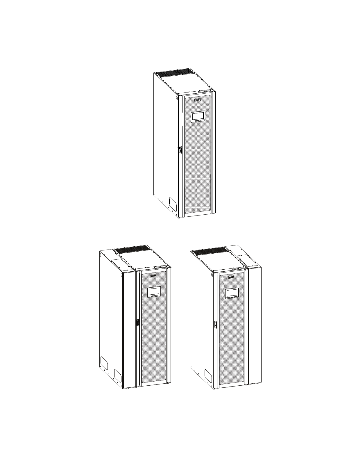
The Eaton®93PM-L 60 kW, Four-Wire uninterruptible power supply (UPS) is a true online, continuous-duty,
transformerless, double-conversion, solid-state, three-phase system, providing conditioned and uninterruptible
AC power to protect the customer's load from power failures.
The Eaton 93PM-L UPS online power protection system is used to prevent loss of valuable electronic
information, minimize equipment downtime, and minimize the adverse effect on production equipment due to
unexpected power problems.
The Eaton 93PM-L UPS continually monitors incoming electrical power and removes the surges, spikes, sags,
and other irregularities that are inherent in commercial utility power. Working with a building's electrical
system, the UPS system supplies clean, consistent power that sensitive electronic equipment requires for
reliable operation. During brownouts, blackouts, and other power interruptions, batteries provide emergency
power to safeguard operation.
The Eaton 93PM-L UPS is available with up to three Uninterruptible Power Modules (UPMs) integrated in one
cabinet. Each UPM is rated for a maximum of 20 kW. The system maximum rating is 60 kW. To deliver greater
reliability, a UPS with two or more UPMs can provide N+1 redundancy up to a maximum of 40 kW. Should one
UPM become unavailable or require servicing, the remaining UPMs supply the load instead of transferring to
bypass.
The UPS is housed in a single free-standing cabinet, with safety shields behind the door for hazardous voltage
protection. Power wiring is installed through the bottom of the cabinet with an optional sidecar available for top
entry wiring. Figure 1 shows the Eaton 93PM-L UPS, Figure 2 shows the Eaton 93PM-L UPS with a left or rightmounted Top Entry Wiring Sidecar, and Figure 3 shows the Eaton 93PM-L UPS with a left or right-mounted
Bypass Sidecar (SIAC-B).
NOTE Startup and operational checks must be performed by an authorized Eaton Customer
11..11 UUPPSS SSttaannddaarrdd FFeeaattuurreess
The UPS has many standard features that provide cost-effective and consistently reliable power protection. The
descriptions in this section provide a brief overview of the UPS standard features.
11..11..11 IInnssttaallllaattiioonn FFeeaattuurreess
• Line-up-and-match or standalone configurations
• Power wiring can be routed through the bottom of the cabinet in standalone configurations or alternately
through the top when configured with an optional accessory sidecar
• Battery wiring can be run internally through the left or right sides of the UPS cabinet in line-up-and-match
configurations
• Easily accessible mechanical terminals located at the bottom front of the cabinet reduce installation time
• Control wiring can be routed through the top or bottom of the UPS cabinet, or through the left or right
sides of the UPS cabinet in line-up-and-match configurations
• Built-in casters for easy cabinet placement
• Cabinet bolt holes are provided for permanently mounting the UPS using optional front and back or left and
right side floor mounting bracket kits
Service Engineer, or the warranty terms specified on the product's resources page
become void. See Chapter 10 Warranty for details. This service is offered as part of the
sales contract for the UPS. Contact an Eaton service representative in advance (a
minimum two-week notice is required) to reserve a preferred startup date.
Eaton 93PM-L 20 – 60 kW (208V) UPS Installation and Operation Manual P-164000711—Rev 03 1
UPS with Left-Mounted UPS with Right-Mounted
Top Entr y Sidecar Top Entry Sidecar
Introduction
Figure 1. Eaton 93PM-L UPS (60 kW, Four-Wire)
Figure 2. Eaton 93PM-L UPS (60 kW, Four-Wire) with Top Entry Wiring Sidecar
2 Eaton 93PM-L 20 – 60 kW (208V) UPS Installation and Operation Manual P-164000711—Rev 03
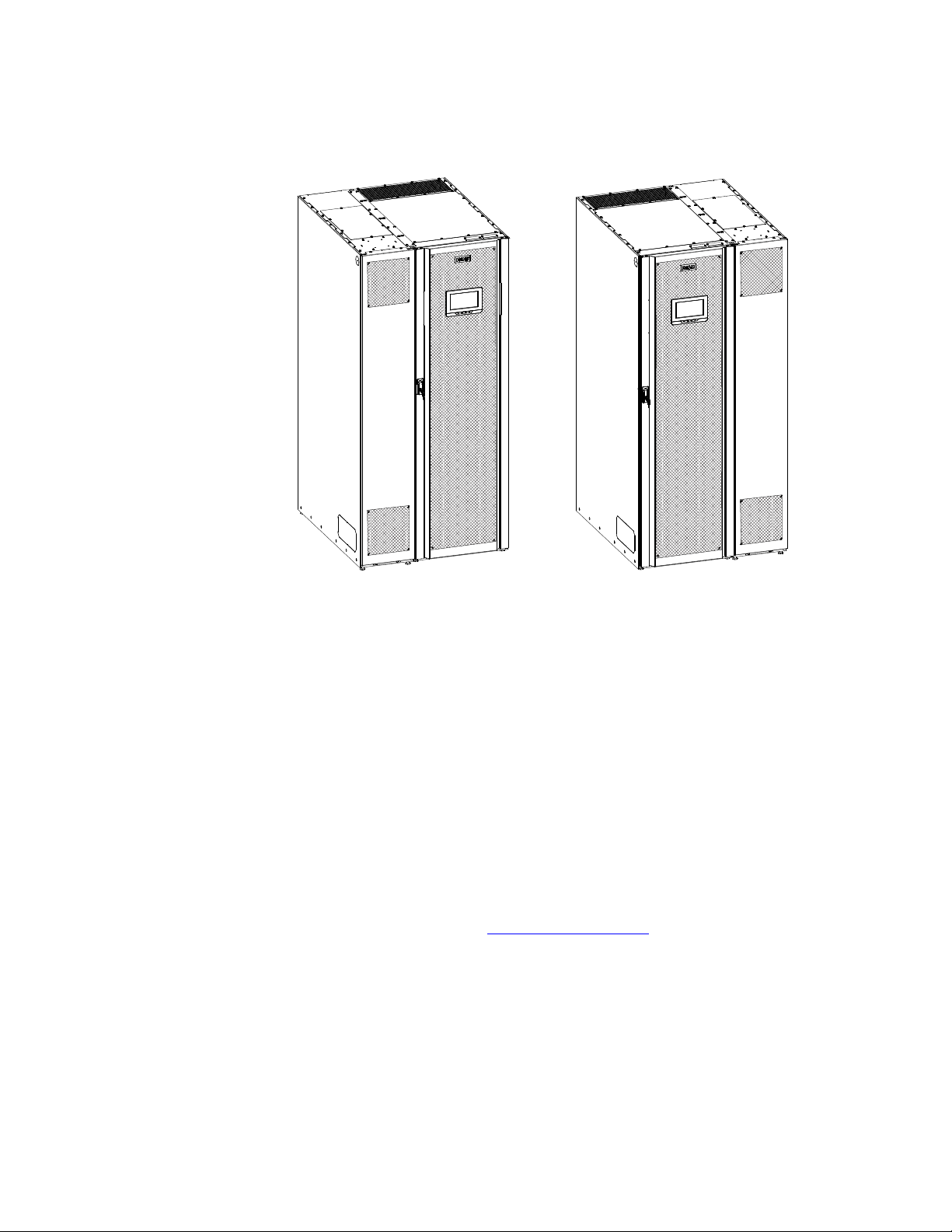
UPS with Left-Mounted Sidecar UPS with Right-Mounted Sidecar
Introduction
Figure 3. Eaton 93PM-L UPS (60 kW, Four-Wire) with Bypass Sidecar (2, 3 or 4 Breaker SIAC-B)
11..11..22 CCoonnttrrooll PPaanneell
The control panel, located on the front of the UPS, contains a color liquid crystal touch screen display (LCD) and
a horizontal row of LED indicators to control the operation of the UPS and to display the status of the UPS
system. See Chapter 6 UPS Operating Instructions, for additional information.
11..11..33 CCuussttoommeerr IInntteerrffaaccee
• Building Alarm Monitoring – Up to five inputs in the UPS are available to connect the facility's alarm
system contacts. Some system configurations may limit the number of inputs available. The UPS uses
these inputs to monitor the building alarms in addition to the UPS status.
• Alarm Contact – One alarm contact is provided for connection to equipment at the facility, such as a light,
an audible alarm, or a computer terminal. The equipment connected to this contact alerts you to a UPS
alarm.
• Minislot Communication Bays – Four communication bays are standard equipment. One to four optional
Minislot
®
connectivity cards can be installed in the UPS at any time. Minislot cards are quickly installed at
the front of the UPS and are hot-pluggable.
For additional information on these topics, see Chapter 7 Communication.
11..11..44 EEnneerrggyy SSaavveerr SSyysstteemm MMooddee
The 93PM-L Series UPS offers an Energy Saver System (ESS) mode that maximizes efficiency by eliminating
unnecessary power conversion when the commercial power source is within acceptable voltage and frequency
limits. In this mode, the UPS is actively monitoring the critical bus and instantly and seamlessly transitions to
double-conversion mode (inverter online) if a commercial electrical power brownout, blackout, overvoltage,
undervoltage, or out-of-tolerance frequency condition occurs. See Chapter 6 UPS Operating Instructions, for
additional information.
Eaton 93PM-L 20 – 60 kW (208V) UPS Installation and Operation Manual P-164000711—Rev 03 3

Introduction
11..11..55 IInntteerrnnaall RReedduunnddaannccyy
To deliver greater reliability, the Eaton 93PM-L UPS can be configured for internal redundancy. When
configured, the UPS automatically becomes redundant if the load is at or below the capacity of the UPMs
minus the capacity of one UPM. Under normal conditions the UPMs in the UPS share the load equally. If one or
more UPMs becomes unavailable and the load is at or below the capacity of remaining UPMs, the remaining
UPMs supply the load instead of transferring to bypass.
11..11..66 AAddvvaanncceedd BBaatttteerryy MMaannaaggeemmeenntt
Advanced Battery Management (ABM) technology uses sophisticated sensing circuitry and a three-stage
charger. The charger is a high-frequency, IGBT-based power conversion stage that extends the useful service
life of UPS batteries by isolating the battery from the electrical environment, except for periodic charging or
reserve mode operation. ABM also protects batteries from damage due to high current charging and inverter
ripple currents. Charging at high currents can overheat and damage batteries.
ABM extends battery life by keeping the batteries charged and performing periodic battery testing. The battery
test checks the batteries by transferring to battery mode. During the test the battery voltage is constantly
monitored to determine Battery Health. ABM is intended for VRLA style batteries.
An ABM charging cycle starts with the charger driving the battery voltage at maximum current limit, to a
battery charge level of 2.30volts/cell. The time it takes for the voltage to reach the battery charge level is saved
as the battery charge time. If the battery charge time exceeds 24 hours, an alarm sounds.
When the battery reaches the float level, the battery is charged at the float level for 48 hours. Due to charger
capability, some battery cabinet configurations extend float level to 72 hours. Twenty-four hours into the float
period, a series of battery tests are performed to check the battery health. The float level charge continues
after a successful test.
After initial startup, the battery run time on the front panel display indicates two minutes. After the 24-hour float
charging period and automated battery testing, the actual battery run time is determined and the actual battery
run time is displayed.
After the float period is completed, the charger is disconnected and the batteries are allowed to rest for up to
672 hours (28 days) maximum rest time. If the battery voltage falls below the opportunity charge level of 2.1V/
cell during the first 240 hours (10 days) of the rest period, an alarm sounds.
An ABM charge cycle is initiated whenever one of these four conditions occurs since the last charge cycle:
• The batteries have rested over the maximum rest time of 672 hours.
• Accumulated discharge time is over a maximum battery discharge time of 20 seconds.
• Battery voltage is under the opportunity charge level of 2.1 volts/cell and the cabinet has been in rest mode
for longer than 240 hours.
• A Battery Test command has been initiated.
11..22 OOppttiioonnss aanndd AAcccceessssoorriieess
Contact an Eaton sales representative for information about the following options.
11..22..11 IInntteeggrraatteedd BBaatttteerryy CCaabbiinneett
Battery backup protection with additional runtime can be provided by equipping the UPS system with up to four
Integrated Battery Cabinets (IBCs) containing sealed lead-acid, maintenance-free batteries. The IBCs are
housed in single, free-standing cabinets designed for line-up-and-match installation, but may be installed
separate from the UPS cabinet. An external battery disconnect switch or tie point must be used when three or
four IBCs are located separate from the UPS cabinet. The IBCs may be installed on either the right or left side
of the UPS cabinet. The recommended installation location for adjacent battery cabinets is on the right side of
the UPS cabinet.
4 Eaton 93PM-L 20 – 60 kW (208V) UPS Installation and Operation Manual P-164000711—Rev 03

Introduction
11..22..22 SSiiddeeccaarr IInntteeggrraatteedd AAcccceessssoorryy CCaabbiinneett--BByyppaassss
A Sidecar Integrated Accessory Cabinet-Bypass (SIAC-B) provides maintenance bypass functions. The SIAC-B
is available in two, three, or four breaker configurations enabling power to completely bypass the UPS. The
UPS can then be safely serviced or replaced without interrupting power to critical systems. Our manufacturing
facility installs the SIAC-B on either the right or left side of the UPS cabinet based on the order requirements.
The SIAC-B can also be used for top entry wiring access.
11..22..33 TToopp EEnnttrryy WWiirriinngg SSiiddeeccaarr
If required, a sidecar is available for top entry power wiring. The sidecar performs the function of a wireway
routing the wires to the terminals mounted at the bottom of the UPS cabinet. The sidecar can be installed on
the left or right side of the UPS cabinet.
11..22..44 IInntteeggrraatteedd AAcccceessssoorryy CCaabbiinneett--PPoowweerr DDiissttrriibbuuttiioonn
The Integrated Accessory Cabinet-Power Distribution (IAC-PD) provides power distribution options for servers,
racks, and other equipment via distribution panelboards, or distributes power to larger loads via distribution
subfeed circuit breakers. The distribution options are customer configurable, enabling adaptation and expansion
without costly electrical rework. The IAC-PD may be installed in a line-and-match or standalone configuration.
The IAC-PD may be installed on either the right or left side of the UPS cabinet.
11..22..55 PPaarraalllleell SSyysstteemm
NOTE All UPSs in a parallel system must have the same battery configuration. Each UPS
requires a separate battery cabinet.
A parallel UPS system with multiple UPSs with a maximum combined wattage of 400 kW can be installed to
provide a parallel capacity and/or redundant system. This load sharing system provides more capacity than a
single UPS, and can provide redundancy, depending on the load and configuration. In addition, when one UPS
is taken out of service for maintenance or is not operating properly, a redundant UPS continues to supply
uninterrupted power to the critical load. A built-in Controller Area Network (CAN) provides connectivity for
system metering and operational mode control. The parallel system consists of two to four UPSs, and a Wall
Mounted Panelboard acting as a tie point and to control the output.
11..22..66 MMoonniittoorriinngg aanndd CCoommmmuunniiccaattiioonn
Minislot Cards – Optional Minislot cards support several protocols, such as SNMP, SMTP, HTTP, Modbus®,
and TCP/IP. See Chapter 7 Communication, for additional information on monitoring and communication
features.
Remote Monitoring Device (RMD) – An optional RMD contains a touch screen status display and a local
audible alarm, allowing monitoring of the operational status and alarm condition of the UPS from virtually any
location within the facility, up to 300 feet from the UPS.
Refer to the Eaton Remote Monitoring Device (RMD) Installation and Operation Manual, listed in
paragraph 1.8 For More Information, for additional information.
PredictPulse™ Remote Monitoring and Management Service – PredictPulse is a subscription monitoring
and management service from Eaton that collects and analyzes data from connected power infrastructure
devices, providing us with the insight needed to make recommendations and take action on your behalf. It’s
also powered by CA Technologies, bringing together the best in hardware and software. Like a second set of
eyes on your power infrastructure, PredictPulse provides 24/7 remote monitoring of alarms and system
performance (load, temperature/humidity, battery health, energy savings and service level) to reduce downtime
risk and expedite repairs. PredictPulse also shares real-time status and trend information via an online
dashboard and smartphone mobile app (Apple and Android), giving subscribers insights about past and current
performance, a list of all active alarms, and asset management data (i.e., battery date codes, last and next
scheduled service dates, firmware versions). The service notifies customers of critical alarms, supports remote
diagnostics, and facilitates smart dispatch of technicians. PredictPulse requires a Power Xpert
®
Gateway
Eaton 93PM-L 20 – 60 kW (208V) UPS Installation and Operation Manual P-164000711—Rev 03 5

Introduction
Minislot (PXGMS) connectivity card in an Minislot communication bay and an Environmental Monitoring Probe
(EMP) for battery temperature/humidity monitoring. See Chapter 7 Communication, for additional information.
11..22..77 AAddddiittiioonnaall OOuuttppuutt SSuurrggee PPrrootteeccttiioonn
The Eaton 93PM-L UPS complies with ANSI 62.41 for line surges. However, if added security is required an
additional Surge Protection Device (SPD) can be installed. For this application, a 208V Delta Style SPD Type 1 or
Type 2 installed on the load side is recommended. The SPD must meet the Maximum Continuous Operating
Voltage (MCOV) for a 208V Delta Style SPD. Eaton offers a variety of SPD solutions including the Eaton SPD
Series with various kA ratings options.
11..33 BBaatttteerryy SSyysstteemm
The battery system provides emergency short-term backup power to safeguard operation during brownouts,
blackouts, and other power interruptions.
11..33..11 BBaatttteerryy CCoonnffiigguurraattiioonnss
The 93PM-L (60 kW) UPS battery system can be internal to the UPS cabinet, an external Integrated Battery
Cabinet/s (IBC), or a combination of both. The external IBCs are connected in parallel with the internal batteries
to provide extended run time. The battery system is equipped with sealed lead-acid, maintenance-free
batteries.
An external battery disconnect switch or tie point must be used when battery systems are located separate
from the UPS cabinet and wiring exceeds the number of battery terminals available.
A supplemental 48 Vdc shunt trip signal for the battery disconnect device is provided by the UPS, but is not
required for normal operation.
11..33..22 OOppttiioonnaall TThheerrmmaall SSeennssoorr
Thermal runaway protection for VRLA batteries can be provided by adding an optional thermal sensor to the
internal battery section or external battery cabinet.
The sensor is wired to the thermal sensor terminal and programmed to turn the charger off when a trip signal is
received.
The thermal sensor will maintain the trip state until it is reset by service. Service should be called to inspect the
batteries and reset the sensor in case of such an event.
11..44 BBaassiicc SSyysstteemm CCoonnffiigguurraattiioonnss
The following basic UPS system configurations are possible:
• Single UPS (20–60 kW) with one to four external battery cabinets
• Single UPS (20–60 kW) with one to four external battery cabinets and accessory cabinets
• Multiple UPSs (20–60 kW to a maximum combined rating of 400 kW) with one to four standard external
battery cabinets for each UPS
• Multiple UPSs (20–60 kW to a maximum combined rating of 400 kW) with one to four standard external
battery cabinets for each UPS and accessory cabinets
The UPS system configuration can be enhanced by adding optional accessories such as a Remote Emergency
Power-off (REPO) control or Minislot communication cards.
6 Eaton 93PM-L 20 – 60 kW (208V) UPS Installation and Operation Manual P-164000711—Rev 03

11..55 UUssiinngg TThhiiss MMaannuuaall
This manual describes how to install and operate the Eaton 93PM-L UPS. Read and understand the procedures
described in this manual to ensure trouble-free installation and operation. In particular, be thoroughly familiar
with the REPO procedure or the LOAD OFF procedure, see Chapter 6 UPS Operating Instructions.
The information in this manual is divided into sections and chapters. The system, options, and accessories
being installed dictate which parts of this manual should be read. At a minimum, Chapter 1 Introduction
through Chapter 4 UPS System Installation and Chapter 6 UPS Operating Instructions should be
examined.
Read through each procedure before beginning the procedure. Perform only those procedures that apply to the
UPS system being installed or operated.
11..66 CCoonnvveennttiioonnss UUsseedd iinn TThhiiss MMaannuuaall
This manual uses these type conventions:
• Bold type highlights important concepts in discussions, key terms in procedures, and menu options, or
represents a command or option that you type or enter at a prompt.
• Italic type highlights notes and new terms where they are defined.
• Screen type represents information that appears on the screen or LCD.
Introduction
Icon
Note Information notes call attention to important features or instructions.
[Keys] Brackets are used when referring to a specific key, such as [Enter] or [Ctrl].
In this manual, the term UPS refers only to the UPS cabinet and its internal elements. The term UPS system
refers to the entire power protection system – the UPS cabinet, an external battery system, and options or
accessories installed.
The term line-up-and-match refers to accessory cabinets that are physically located adjacent to the UPS. The
term standalone refers to accessory cabinets that are located separate from the UPS.
Left and right side notations are referenced standing in front of the cabinet.
Description
Eaton 93PM-L 20 – 60 kW (208V) UPS Installation and Operation Manual P-164000711—Rev 03 7
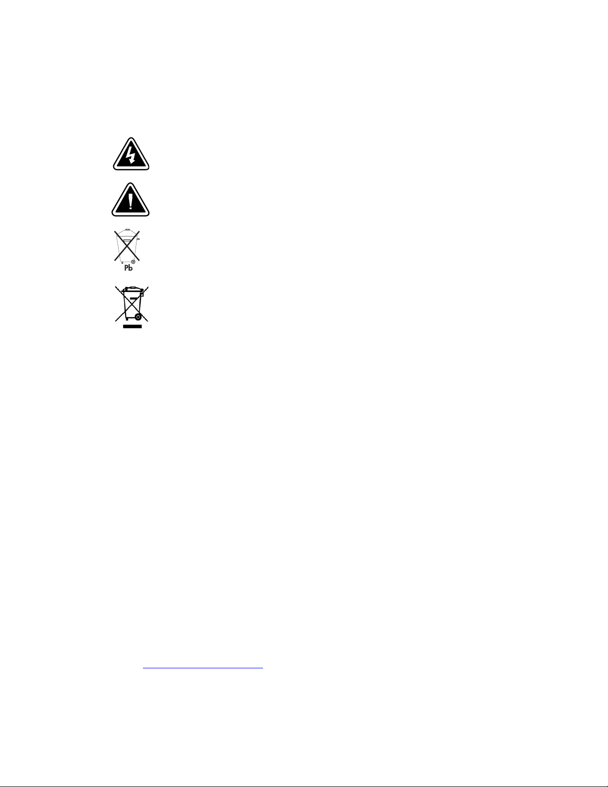
RISK OF ELECTRIC SHOCK - Observe the warning associated with the risk of
electric shock symbol.
RISK OF ELECTRIC SHOCK - Observe the warning associated with the risk of
electric shock symbol.
CAUTION: REFER TO OPERATOR'S MANUAL - Refer to your operator's manual for
additional information, such as important operating and maintenance
instructions.
RISK OF ELECTRIC SHOCK - Observe the warning associated with the risk of
electric shock symbol.
CAUTION: REFER TO OPERATOR'S MANUAL - Refer to your operator's manual for
additional information, such as important operating and maintenance
instructions.
This symbol indicates that you should not discard the UPS or the UPS batteries
in the trash. This product contains sealed, lead‐acid batteries and must be
disposed of properly. For more information, contact your local recycling/reuse or
hazardous waste center.
This symbol indicates that you should not discard waste electrical or electronic
equipment (WEEE) in the trash. For proper disposal, contact your local
recycling/reuse or hazardous waste center.
Introduction
11..77 SSyymmbboollss,, CCoonnttrroollss,, aanndd IInnddiiccaattoorrss
The following are examples of symbols used on the UPS or accessories to alert you to important information:
RISK OF ELECTRIC SHOCK - Observe the warning associated with the risk of electric shock symbol.
CAUTION: REFER TO OPERATOR'S MANUAL - Refer to your operator's manual for additional
information, such as important operating and maintenance instructions.
This symbol indicates that you should not discard the UPS or the UPS batteries in the trash. This
product contains sealed, lead-acid batteries and must be disposed of properly. For more information,
contact your local recycling/reuse or hazardous waste center.
This symbol indicates that you should not discard waste electrical or electronic equipment (WEEE) in
the trash. For proper disposal, contact your local recycling/reuse or hazardous waste center.
11..88 FFoorr MMoorree IInnffoorrmmaattiioonn
Refer to the Eaton 93PM Integrated Battery Cabinet Installation Manual-Small Welded, or the Eaton
93PM Universal Integrated Battery Cabinet Installation Manual-Large and Large High Rate for the
following additional information:
• Installation instructions, including site preparation, planning for installation, wiring and safety information,
and detailed illustrations of cabinets with dimensional and connection point drawings
Refer to the Eaton 93PM–L Sidecar Integrated Accessory Cabinet (60 kW Top Entry Wiring Sidecar, 60
kW SIAC-B, 120 kW Top Entry Wiring Sidecar, and 120 kW SIAC-B) Installation and Operation Manual
for the following additional information:
• Installation instructions, including site preparation, planning for installation, wiring and safety information,
and detailed illustrations of cabinets with dimensional and connection point drawings
• Operation, including breakers, standard features and optional accessories, procedures for using the bypass
functions, and information about maintenance
Refer to the Eaton 93PM Integrated Accessory Cabinet-Power Distribution (208V 4–Wire IAC-PD, 480V 3–
Wire IAC-PD, 480V 4–Wire IAC-PD) Installation and Operation Manual for the following additional
information:
• Installation instructions, including site preparation, planning for installation, wiring and safety information,
and detailed illustrations of cabinets with dimensional and connection point drawings
8 Eaton 93PM-L 20 – 60 kW (208V) UPS Installation and Operation Manual P-164000711—Rev 03
• Operation, including breakers, standard features and optional accessories, procedures for using the bypass
functions, and information about maintenance
Refer to the Eaton Remote Monitoring Device (RMD) Installation and Operation Manual for additional
installation and operating instructions.
• Visit www.eaton.com/powerquality or contact an Eaton service representative for information on how to
obtain copies of these manuals.

11..99 GGeettttiinngg HHeellpp
If help is needed with any of the following:
• Scheduling initial startup
• Regional locations and telephone numbers
• A question about any of the information in this manual
• A question this manual does not answer
Please call the Customer Reliability Center at:
Introduction
United States:
Canada:
All other countries: Call your local service representative
Please use the following e-mail address for manual comments, suggestions, or to report an error in this
manual:
E-ESSDocumentation@eaton.com
11..1100 EEqquuiippmmeenntt RReeggiissttrraattiioonn
Please visit www.eaton.com/pq/register to register your new Eaton UPS / Eaton UPS Accessory.
Model Number:
Serial Number:
1-800-843-9433
1-800-461-9166 ext 260
Eaton 93PM-L 20 – 60 kW (208V) UPS Installation and Operation Manual P-164000711—Rev 03 9

Introduction
10 Eaton 93PM-L 20 – 60 kW (208V) UPS Installation and Operation Manual P-164000711—Rev 03

CChhaapptteerr 22 SSaaffeettyy WWaarrnniinnggss
IMPORTANT SAFETY INSTRUCTIONS SAVE THESE INSTRUCTIONS
This manual contains important instructions that should be followed during installation and maintenance of the
UPS and batteries. Read all instructions before operating the equipment and save this manual for future
reference.
The UPS is designed for industrial or computer room applications, and contains safety shields behind the door
and front panels. However, the UPS is a sophisticated power system and should be handled with appropriate
care.
This UPS contains LETHAL VOLTAGES. All repairs and service should be performed by AUTHORIZED SERVICE
PERSONNEL ONLY. There are NO USER SERVICEABLE PARTS inside the UPS.
• The UPS is powered by its own energy source (batteries). The output terminals may carry live voltage even
when the UPS is disconnected from an AC source.
• To reduce the risk of fire or electric shock, install this UPS in a temperature and humidity controlled, indoor
environment, free of conductive contaminants. Ambient temperature must not exceed 40°C (104°F). Do
not operate near water or excessive humidity (95% maximum). The system is not intended for outdoor
use.
• As a result of the connected loads high leakage current is possible. Connection to earth ground is required
for safety and proper product operation. Do not check UPS operation by any action that includes removal of
the earth (ground) connection with loads attached.
• Emergency Power Off (EPO) and Remote Emergency Power Off (REPO) functionality is disabled for UPS
systems configured for UL 924 auxiliary lighting. To remove power from the system a LOAD OFF
command must be given using the front panel controls and all breakers opened. Review Chapter 6 UPS
Operating Instructions, for details.
• Ensure all power is disconnected before performing installation or service.
• Batteries can present a risk of electrical shock or burn from high short-circuit current. The following
precautions should be observed: 1) Remove watches, rings, or other metal objects; 2) Use tools with
insulated handles; 3) Do not lay tools or metal parts on top of batteries; 4) Wear voltage rated gloves and
electrical hazard footwear.
• ELECTRIC ENERGY HAZARD. Do not attempt to alter any UPS or battery wiring or connectors. Attempting
to alter wiring can cause injury.
• Do not open or mutilate batteries. Released electrolyte is harmful to the skin and eyes. It may be toxic.
DANGER
WARNING
Eaton 93PM-L 20 – 60 kW (208V) UPS Installation and Operation Manual P-164000711—Rev 03 11

Safety Warnings
• Installation or servicing should be performed by qualified service personnel knowledgeable of UPS and
• Replace batteries with the same number and type of batteries as originally installed with the UPS.
• Disconnect the charging source prior to connecting or disconnecting terminals.
• Determine if the battery is inadvertently grounded. If it is, remove the source of the ground. Contacting any
• Proper disposal of batteries is required. Refer to local codes for disposal requirements.
• Do not dispose of batteries in a fire. Batteries may explode when exposed to flame.
• Keep the UPS door closed and front panels installed to ensure proper cooling airflow and to protect
• Do not install or operate the UPS system close to gas or electric heat sources.
• Lead-acid batteries can present a risk of fire because they generate hydrogen gas. Do not smoke when
• The operating environment should be maintained within the parameters stated in this manual.
• Keep surroundings uncluttered, clean, and free from excess moisture.
• Observe all DANGER, CAUTION, and WARNING notices affixed to the inside and outside of the
CAUTION
battery systems, and required precautions. Keep unauthorized personnel away from equipment. Consider
all warnings, cautions, and notes before installing or servicing equipment. DO NOT DISCONNECT the
batteries while the UPS is in Battery mode.
part of a grounded battery can cause a risk of electric shock. An electric shock is less likely if you
disconnect the grounding connection before you work on the batteries.
personnel from dangerous voltages inside the unit.
near batteries. Do not cause flame or spark in battery area. Discharge static electricity from body before
touching batteries by first touching a grounded metal surface.
equipment.
AVERTISSEMENT!
• Les batteries peuvent présenter un risque de décharge électrique ou de brûlure par des courts–circuits de
haute intensité. Prendre les précautions nécessaires.
• Pour le replacement, utiliser le même nombre et modéle des batteries.
ATTENTION!
• Une mise au rebut réglementaire des batteries est obligatoire. Consulter les règlements en vigueur dans
votre localité.
• Ne jamais jeter les batteries au feu. L'exposition aux flammes risque de les faire exploser.
• Les accumulateurs au plomb-acide peuvent représenter un risque d’incendie, car ils génèrent de
l’hydrogène gazeux. Ne pas fumer près des accumulateurs. Ne pas produire de flamme ou d’étincelle dans
la zone de l’accumulateur. Dissiper l'électricité statique de votre corps en touchant une surface reliée à la
terre avant de toucher les accumulateurs.
12 Eaton 93PM-L 20 – 60 kW (208V) UPS Installation and Operation Manual P-164000711—Rev 03

CChhaapptteerr 33 UUPPSS IInnssttaallllaattiioonn PPllaann aanndd UUnnppaacckkiinngg
Use the following basic sequence of steps to install the UPS:
1. Create an installation plan for the UPS system.
2. Prepare your site for the UPS system.
3. Inspect and unpack the UPS cabinet.
4. Unload and install the UPS cabinet, and wire the system.
5. Complete the Installation Checklist.
6. Have authorized service personnel perform preliminary operational checks and start up the system.
NOTE Startup and operational checks must be performed by an authorized Eaton Customer
Service Engineer, or the warranty terms specified on the product's resources page
become void. See Chapter 10 Warranty for details. This service is offered as part of the
sales contract for the UPS. Contact an Eaton service representative in advance (a
minimum two-week notice is required) to reserve a preferred startup date.
33..11 CCrreeaattiinngg aann IInnssttaallllaattiioonn PPllaann
Before installing the UPS system, read and understand how this manual applies to the system being installed.
Use this chapter’s procedures and illustrations and those in Chapter 4 UPS System Installation to create a
logical plan for installing the system.
33..22 PPrreeppaarriinngg tthhee SSiittee
For the UPS system to operate at peak efficiency, the installation site should meet the environmental
parameters outlined in this manual. The operating environment must meet the weight, clearance, and
environmental requirements specified.
33..22..11 EEnnvviirroonnmmeennttaall aanndd IInnssttaallllaattiioonn CCoonnssiiddeerraattiioonnss
The UPS system installation must meet the following guidelines:
• The system must be installed on a level floor suitable for computer or electronic equipment.
• The system must be operated at an altitude no higher than 1500m (5000 ft) without derating. For additional
assistance with high altitude operation, contact an Eaton service representative (see paragraph
1.9 Getting Help).
• The system must be installed in a temperature and humidity controlled indoor area free of conductive
contaminants.
CAUTION
Do not expose the UPS to overly aggressive environments, like salt mist or corrosive gases. High relative
humidity accelerates the effects of contaminants. The UPS should be installed in a G1 environment (based on
ANSI/ISA S-71.04 classifications). If the UPS is used in a more aggressive environment, it can cause reduced
product life and possibly early failure. If the installation location does not meet the recommended environment,
contact Eaton service representative for further information (see paragraph 1.9 Getting Help).
• The environmental requirements specified below are for the air at the intake ports of the 93PM UPS, and
are the maximum, not to exceed, ratings.
– There shall be at least a 1.8°F (1.0°C) difference between the dry bulb temperature and the wet bulb
temperature, at all times, to maintain a non-condensing environment.
Eaton 93PM-L 20 – 60 kW (208V) UPS Installation and Operation Manual P-164000711—Rev 03 13

UPS Installation Plan and Unpacking
– The maximum rate of temperature change shall be limited to 3°F over 5 minutes (36°F/hour), based on
the ASHRAE Standard 90.1-2013.
• The newer, more energy efficient data center cooling methods (such as air side economization) can create
much wider ranges of temperature and Relative Humidity (RH) in the UPS room and/or data center. There
are two aspects of this increased operating environment that can, if ignored, create issues.
– One is the creation of microclimates, which are persistent variations of temperature and/or RH within
a single room. For example one side of the room is always cooler than the other side, no matter the
actual temperature.
– The other aspect is the rate of change of temperature and/or RH, which can occur during transitions
within the cooling system. Examples: changing the mixture ratio of inside versus outside air, or
external changes in the outside air when going from night to day, and back to night.
– When ignored, either one of these aspects can create an undesirable microclimate at the UPS
location. If the environment created by this microclimate exceeds the UPS operating specification, the
UPS reliability, over time, will be reduced. These same environmental extremes will also create
reliability concerns for any servers that are exposed to them.
Failure to follow guidelines may void your warranty.
The basic environmental requirements for operation of the UPS are:
• Ambient Temperature Range: 5–40°C (41–104°F)
• Recommended Operating Range: 5–40°C (41–104°F)
• Maximum Relative Humidity: 5–95%, noncondensing
CAUTION
If battery systems are located in the same room as the UPS, the battery manufacturer's environmental
requirements should be followed if they are more stringent than the UPS requirements. Operating
temperatures above the recommended range will result in decreased battery life and performance, and may
reduce or void the battery warranty.
The UPS ventilation requirements are shown in Table 1. To allow for future power upgrades, Eaton
recommends using air conditioning or ventilation sized for the fully rated UPS kW frame size installed instead of
the derated kW ordered. Sizing the site cooling infrastructure to be capable of cooling the maximum kW frame
size will allow a full power rating upgrade without having to modify the infrastructure.
14 Eaton 93PM-L 20 – 60 kW (208V) UPS Installation and Operation Manual P-164000711—Rev 03

UPS Installation Plan and Unpacking
Table 1. Air Conditioning or Ventilation Requirements During Full Load Operation
Max Heat Dissipation at 100%
Load
Model
UPS Rating
KW (BTU/Hr)
Minimum Required
Cooling Air Flow
Eaton 93PM-L 60-1
Eaton 93PM-L 60-2 (N+1)
Eaton 93PM-L 60-1
Eaton 93PM-L 60-2 (N+1)
Eaton 93PM-L 60-2
Eaton 93PM-L 60-3 (N+1)
Eaton 93PM-L 60-2
Eaton 93PM-L 60-3 (N+1)
Eaton 93PM-L 60-3
Eaton 93PM-L 60-3
The UPS equipment operating environment must meet the weight requirements shown inTable 2 through
Table 4 and the size requirements shown in Figure 4 through Figure 15. Dimensions are in millimeters (inches).
Table 2. 93PM-L 60 kW UPS Cabinet Weights
Number
Model
of UPMs
1 UPM Installed
10 kW .90 (3063)
20 kW 1.80 (6125)
30 kW 2.69 (9188)
40 kW 3.59 (12250)
50 kW 4.49 (15313) 295 liter/sec (625 cfm)
60 kW 5.39 (18375) 295 liter/sec (625 cfm)
Number of
Battery Strings
0 Battery Strings
2 Battery Strings
3 Battery Strings
Shipping
290 (637) 259 (570) 4 at 65 (143)
515 (1132) 484 (1065) 4 at 121 (266)
604 (1327) 573 (1260) 4 at 143 (315)
130 liter/sec (275 cfm)
212 liter/sec (450 cfm)
130 liter/sec (275 cfm)
212 liter/sec (450 cfm)
212 liter/sec (450 cfm)
295 liter/sec (625 cfm)
212 liter/sec (450 cfm)
295 liter/sec (625 cfm)
Weight kg (lb)
Installed
Point Loading
Eaton 93PM-L
60 kW UPS
4 Battery Strings
0 Battery Strings
2 UPMs Installed
3 UPMs Installed
Eaton 93PM-L 20 – 60 kW (208V) UPS Installation and Operation Manual P-164000711—Rev 03 15
(1+1), 2 Battery Strings
3 Battery Strings
4 Battery Strings
0 Battery Strings
(2+1), 3 Battery Strings
4 Battery Strings
692 (1522) 661 (1455) 4 at 165 (364)
321 (706) 290 (639) 4 at 73 (160)
546 (1396) 515 (1134) 4 at 129 (284)
635 (1396) 604 (1329) 4 at 151 (332)
724 (1591) 693 (1524) 4 at 173 (381)
353 (775) 322 (708) 4 at 81 (177)
666 (1465) 635 (1398) 4 at 159 (350)
755 (1660) 724 (1593) 4 at 181 (398)

UPS Installation Plan and Unpacking
Table 3. 93PM-L 60 kW UPS with Top Entry Sidecar Cabinet Weights
Model
Eaton 93PM-L 60 kW UPS
with
Left or Right-Mounted
Top Entry Sidecar
(No Breakers)
Number
of UPMs
1 UPM Installed
2 UPMs Installed
3 UPMs Installed
Number of
Battery Strings
0 Battery Strings
2 Battery Strings
3 Battery Strings
4 Battery Strings
0 Battery Strings
(1+1), 2 Battery
Strings
3 Battery Strings
4 Battery Strings
0 Battery Strings
(2+1), 3 Battery
Strings
4 Battery Strings
Weight kg (lb)
Shipping
368 (809) 337 (742) 6 at 56 (124)
593 (1304) 562 (1237) 6 at 94 (206)
682 (1499) 651 (1432) 6 at 109 (239)
771 (1694) 740 (1627) 6 at 123 (271)
400 (878) 369 (811) 6 at 62 (135)
625 (1373) 594 (1306) 6 at 99 (218)
713 (1568) 682 (1501) 6 at 114 (250)
802 (1763) 771 (1696) 6 at 129 (283)
431 (947) 400 (880) 6 at 67 (147)
745 (1637) 714 (1570) 6 at 119 (262)
833 (1832) 802 (1765) 6 at 134 (294)
Installed
Point Loading
Table 4. 93PM-L 60 kW UPS with SIAC-B Cabinet Weights
Number of
Battery Strings
0 Battery Strings
2 Battery Strings
3 Battery Strings
4 Battery Strings
0 Battery Strings
(1+1), 2 Battery
Strings
3 Battery Strings
4 Battery Strings
0 Battery Strings
(2+1), 3 Battery
Strings
4 Battery Strings
Model
Eaton 93PM-L 60 kW UPS
with
Left or Right-Mounted Sidecar
(2 Breakers)
Number
of UPMs
1 UPM Installed
2 UPMs Installed
3 UPMs Installed
Weight kg (lb)
Shipping
436 (959) 405 (892) 6 at 68 (149)
661 (1454) 630 (1387) 6 at 105 (231)
750 (1649) 719 (1582) 6 at 120 (264)
839 (1844) 808 (1777) 6 at 135 (296)
468 (1028) 437 (961) 6 at 73 (160)
693 (1523) 662 (1456) 6 at 110 (243)
781 (1718) 750 (1651) 6 at 125 (275)
870 (1913) 839 (1846) 6 at 140 (308)
499 (1097) 468 (1030) 6 at 78 (172)
813 (1787) 782 (1720) 6 at 130 (287)
901 (1982) 870 (1915) 6 at 145 (319)
Installed
Point Loading
16 Eaton 93PM-L 20 – 60 kW (208V) UPS Installation and Operation Manual P-164000711—Rev 03

Table 4. 93PM-L 60 kW UPS with SIAC-B Cabinet Weights (Continued)
UPS Installation Plan and Unpacking
Model
Eaton 93PM-L 60 kW UPS
with
Left or Right-Mounted Sidecar
(3 Breakers)
Number
of UPMs
1 UPM Installed
2 UPMs Installed
3 UPMs Installed
1 UPM Installed
Number of
Battery Strings
0 Battery Strings
2 Battery Strings
3 Battery Strings
4 Battery Strings
0 Battery Strings
(1+1), 2 Battery
Strings
3 Battery Strings
4 Battery Strings
0 Battery Strings
(2+1), 3 Battery
Strings
4 Battery Strings
0 Battery Strings
2 Battery Strings
3 Battery Strings
Weight kg (lb)
Shipping
456 (1001) 425 (934) 6 at 71 (156)
681 (1496) 650 (1429) 6 at 108 (238)
769 (1691) 738 (1624) 6 at 123 (271)
858 (1886) 827 (1819) 6 at 138 (303)
487 (1070) 456 (1003) 6 at 76 (167)
712 (1565) 681 (1498) 6 at 114 (250)
801 (1760) 770 (1693) 6 at 128 (282)
889 (1955) 858 (1888) 6 at 143 (315)
518 (1139) 487 (1072) 6 at 81 (179)
832 (1829) 801 (1762) 6 at 134 (294)
921 (2024) 890 (1957) 6 at 148 (326)
471 (1036) 440 (969) 6 at 73 (162)
696 (1531) 665 (1464) 6 at 111 (244)
785 (1726) 754 (1659) 6 at 126 (277)
Installed
Point Loading
4 Battery Strings
0 Battery Strings
Eaton 93PM-L 60 kW UPS
with
Left or Right-Mounted Sidecar
(4 Breakers)
The UPS cabinet uses forced air cooling to regulate internal component temperature. Air inlets are in the front
of the cabinet and outlets are on top or in the back of the cabinet. Allow clearance in front of and on top or in
back of the cabinet for proper air circulation. The clearances required around the UPS cabinet are shown in the
following table.
2 UPMs Installed
3 UPMs Installed
(1+1), 2 Battery
Strings
3 Battery Strings
4 Battery Strings
0 Battery Strings
(2+1), 3 Battery
Strings
4 Battery Strings
874 (1921) 843 (1854) 6 at 141 (309)
503 (1105) 472 (1038) 6 at 79 (173)
728 (1600) 697 (1533) 6 at 116 (256)
816 (1795) 785 (1728) 6 at 131 (288)
905 (1990) 874 (1923) 6 at 146 (321)
534 (1174) 503 (1107) 6 at 84 (185)
848 (1864) 817 (1797) 6 at 136 (300)
936 (2059) 905 (1992) 6 at 151 (332)
Eaton 93PM-L 20 – 60 kW (208V) UPS Installation and Operation Manual P-164000711—Rev 03 17
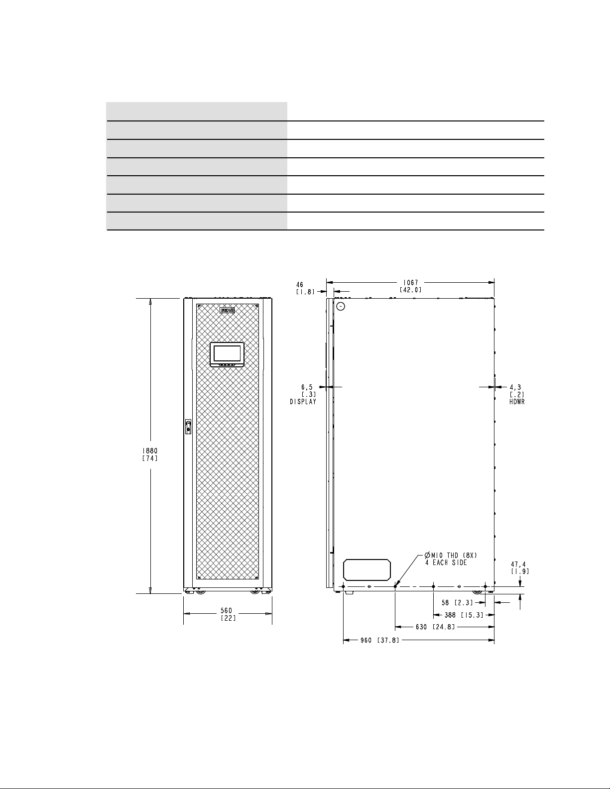
Dimensions are in millimeters [inches]
Front View Side View
UPS Installation Plan and Unpacking
Table 5. UPS Cabinet Clearances
From Front of Cabinet
From Top of Cabinet with Top Exhaust 457 mm (18") minimum clearance for ventilation
From Top of Cabinet with Rear Exhaust 457 mm (18”)
914 mm (36") working space
From Back of Cabinet with Rear Exhaust
457 mm (18") minimum clearance for ventilation
From Back of Cabinet with Top Exhaust None Required
From Right Side of Cabinet None Required
From Left Side of Cabinet
None Required
Figure 4. UPS Cabinet Dimensions (Front and Right Side Views)
18 Eaton 93PM-L 20 – 60 kW (208V) UPS Installation and Operation Manual P-164000711—Rev 03
 Loading...