

Eaton 93PM-L Installation And Operation Manual

Eaton® 93PM-L UPS
20 – 120 kW (208V) UPS
Installation and Operation Manual


Eaton® 93PM-L UPS
20 – 120 kW (208V) UPS
Installation and Operation Manual

IMPORTANT SAFETY INSTRUCTIONS SAVE THESE INSTRUCTIONS
This manual contains important instructions that you should follow during installation and
CONSIGNES DE SÉCURITÉ IMPORTANTES CONSERVER CES INSTRUCTIONS
maintenance of the UPS and batteries. Please read all instructions before operating the equipment
and save this manual for future reference.
Ce manuel comporte des instructions importantes que vous êtes invité à suivre lors de toute
procédure d'installation et de maintenance des batteries et de l'onduleur. Veuillez consulter
entièrement ces instructions avant de faire fonctionner l'équipement et conserver ce manuel afin
de pouvoir vous y reporter ultérieurement.
Eaton and Mini-Slot are registered trademarks of Eaton or its subsidiaries and affiliates. Modbus is a registered
trademark of Schneider Electric. National Electrical Code and NEC are registered trademarks of National Fire
Protection Association, Inc. All other trademarks are property of their respective companies.
©Copyright 2017 Eaton, Raleigh, NC, USA. All rights reserved. No part of this document may be reproduced in
any way without the express written approval of Eaton.

Table of Contents
1 INTRODUCTION . . . . . . . . . . . . . . . . . . . . . . . . . . . . . . . . . . . . . . . . . . . . . . . . . . . . . . . . . . . . . . . . . . . . . . . . . . . . . . . . . . . . . . 1-1
1.1 UPS Standard Features . . . . . . . . . . . . . . . . . . . . . . . . . . . . . . . . . . . . . . . . . . . . . . . . . . . . . . . . . . . . . . . . . 1-1
1.1.1 Installation Features. . . . . . . . . . . . . . . . . . . . . . . . . . . . . . . . . . . . . . . . . . . . . . . . . . . . . . . . . . . . . . . 1-1
1.1.2 Control Panel . . . . . . . . . . . . . . . . . . . . . . . . . . . . . . . . . . . . . . . . . . . . . . . . . . . . . . . . . . . . . . . . . . . . 1-3
1.1.3 Customer Interface . . . . . . . . . . . . . . . . . . . . . . . . . . . . . . . . . . . . . . . . . . . . . . . . . . . . . . . . . . . . . . . 1-3
1.1.4 Energy Saver System Mode . . . . . . . . . . . . . . . . . . . . . . . . . . . . . . . . . . . . . . . . . . . . . . . . . . . . . . . . 1-3
1.1.5 Internal Redundancy . . . . . . . . . . . . . . . . . . . . . . . . . . . . . . . . . . . . . . . . . . . . . . . . . . . . . . . . . . . . . . 1-3
1.1.6 Advanced Battery Management . . . . . . . . . . . . . . . . . . . . . . . . . . . . . . . . . . . . . . . . . . . . . . . . . . . . . 1-3
1.2 Options and Accessories. . . . . . . . . . . . . . . . . . . . . . . . . . . . . . . . . . . . . . . . . . . . . . . . . . . . . . . . . . . . . . . . 1-4
1.2.1 Integrated Battery Cabinet. . . . . . . . . . . . . . . . . . . . . . . . . . . . . . . . . . . . . . . . . . . . . . . . . . . . . . . . . . 1-4
1.2.2 Sidecar Integrated Accessory Cabinet-Bypass . . . . . . . . . . . . . . . . . . . . . . . . . . . . . . . . . . . . . . . . . . 1-4
1.2.3 Top Entry Wiring Sidecar . . . . . . . . . . . . . . . . . . . . . . . . . . . . . . . . . . . . . . . . . . . . . . . . . . . . . . . . . . . 1-4
1.2.4 Monitoring and Communication . . . . . . . . . . . . . . . . . . . . . . . . . . . . . . . . . . . . . . . . . . . . . . . . . . . . . 1-5
1.2.5 Additional Output Surge Protection . . . . . . . . . . . . . . . . . . . . . . . . . . . . . . . . . . . . . . . . . . . . . . . . . . . 1-5
1.3 Battery System . . . . . . . . . . . . . . . . . . . . . . . . . . . . . . . . . . . . . . . . . . . . . . . . . . . . . . . . . . . . . . . . . . . . . . . 1-5
1.4 Basic System Configurations. . . . . . . . . . . . . . . . . . . . . . . . . . . . . . . . . . . . . . . . . . . . . . . . . . . . . . . . . . . . . 1-5
1.5 Using This Manual. . . . . . . . . . . . . . . . . . . . . . . . . . . . . . . . . . . . . . . . . . . . . . . . . . . . . . . . . . . . . . . . . . . . . 1-6
1.6 Conventions Used in This Manual. . . . . . . . . . . . . . . . . . . . . . . . . . . . . . . . . . . . . . . . . . . . . . . . . . . . . . . . . 1-6
1.7 Symbols, Controls, and Indicators. . . . . . . . . . . . . . . . . . . . . . . . . . . . . . . . . . . . . . . . . . . . . . . . . . . . . . . . . 1-7
1.8 For More Information . . . . . . . . . . . . . . . . . . . . . . . . . . . . . . . . . . . . . . . . . . . . . . . . . . . . . . . . . . . . . . . . . . 1-7
1.9 Getting Help . . . . . . . . . . . . . . . . . . . . . . . . . . . . . . . . . . . . . . . . . . . . . . . . . . . . . . . . . . . . . . . . . . . . . . . . . 1-7
2 SAFETY WARNINGS . . . . . . . . . . . . . . . . . . . . . . . . . . . . . . . . . . . . . . . . . . . . . . . . . . . . . . . . . . . . . . . . . . . . . . . . . . . . . . . . . . 2-1
3 UPS INSTALLATION PLAN AND UNPACKING . . . . . . . . . . . . . . . . . . . . . . . . . . . . . . . . . . . . . . . . . . . . . . . . . . . . . . . . . . . . 3-1
3.1 Creating an Installation Plan . . . . . . . . . . . . . . . . . . . . . . . . . . . . . . . . . . . . . . . . . . . . . . . . . . . . . . . . . . . . . 3-1
3.2 Preparing the Site . . . . . . . . . . . . . . . . . . . . . . . . . . . . . . . . . . . . . . . . . . . . . . . . . . . . . . . . . . . . . . . . . . . . . 3-1
3.2.1 Environmental and Installation Considerations . . . . . . . . . . . . . . . . . . . . . . . . . . . . . . . . . . . . . . . . . . 3-1
3.2.2 UPS System Power Wiring Preparation. . . . . . . . . . . . . . . . . . . . . . . . . . . . . . . . . . . . . . . . . . . . . . . . 3-14
3.2.3 UPS System Interface Wiring Preparation. . . . . . . . . . . . . . . . . . . . . . . . . . . . . . . . . . . . . . . . . . . . . . 3-24
3.3 Inspecting and Unpacking the UPS Cabinets . . . . . . . . . . . . . . . . . . . . . . . . . . . . . . . . . . . . . . . . . . . . . . . . 3-25
4 UPS SYSTEM INSTALLATION . . . . . . . . . . . . . . . . . . . . . . . . . . . . . . . . . . . . . . . . . . . . . . . . . . . . . . . . . . . . . . . . . . . . . . . . . . 4-1
4.1 Preliminary Installation Information . . . . . . . . . . . . . . . . . . . . . . . . . . . . . . . . . . . . . . . . . . . . . . . . . . . . . . . . 4-1
4.2 Unloading the UPS Cabinet from the Pallet. . . . . . . . . . . . . . . . . . . . . . . . . . . . . . . . . . . . . . . . . . . . . . . . . . 4-1
4.3 Integrated Battery Cabinet Installation . . . . . . . . . . . . . . . . . . . . . . . . . . . . . . . . . . . . . . . . . . . . . . . . . . . . . 4-6
4.4 External AC Power Wiring Installation. . . . . . . . . . . . . . . . . . . . . . . . . . . . . . . . . . . . . . . . . . . . . . . . . . . . . . 4-6
4.4.1 Standalone UPS or UPS with Pass-Through Sidecar (No Breakers). . . . . . . . . . . . . . . . . . . . . . . . . . . 4-7
4.4.2 UPS with 2-Breaker Sidecar (MBP and MIS). . . . . . . . . . . . . . . . . . . . . . . . . . . . . . . . . . . . . . . . . . . . 4-8
4.4.3 UPS with 3-Breaker Sidecar (BIB, MBP and MIS).. . . . . . . . . . . . . . . . . . . . . . . . . . . . . . . . . . . . . . . . 4-9
4.4.4 UPS with 4 -Breaker Sidecar (RIB, BIB, MBP and MIS). . . . . . . . . . . . . . . . . . . . . . . . . . . . . . . . . . . . 4-10
4.5 Battery Power Wiring . . . . . . . . . . . . . . . . . . . . . . . . . . . . . . . . . . . . . . . . . . . . . . . . . . . . . . . . . . . . . . . . . . 4-20
4.6 Installing Interface Connections . . . . . . . . . . . . . . . . . . . . . . . . . . . . . . . . . . . . . . . . . . . . . . . . . . . . . . . . . . 4-20
4.6.1 Installing Building Alarm and Relay Contact Connections . . . . . . . . . . . . . . . . . . . . . . . . . . . . . . . . . . 4-20
4.6.2 Installing Sidecar MIS and RIB Breaker Monitoring Connections . . . . . . . . . . . . . . . . . . . . . . . . . . . . 4-25
4.6.3 Installing Battery Detect Interface Connections . . . . . . . . . . . . . . . . . . . . . . . . . . . . . . . . . . . . . . . . . 4-27
4.6.4 Installing Battery Shunt Trip Interface Connections. . . . . . . . . . . . . . . . . . . . . . . . . . . . . . . . . . . . . . . 4-28
Eaton 93PM-L UPS (20–120 kW, 208V) Installation and Operation Manual P-164000688—Rev 02 www.eaton.com/powerquality i

Table of Contents
4.6.5 Generator Interface Connections . . . . . . . . . . . . . . . . . . . . . . . . . . . . . . . . . . . . . . . . . . . . . . . . . . . . . 4-32
4.6.6 Installing Minislot Interface Connections . . . . . . . . . . . . . . . . . . . . . . . . . . . . . . . . . . . . . . . . . . . . . . . 4-33
4.7 Installing a REPO Switch. . . . . . . . . . . . . . . . . . . . . . . . . . . . . . . . . . . . . . . . . . . . . . . . . . . . . . . . . . . . . . . . . 4-34
4.8 Initial Startup . . . . . . . . . . . . . . . . . . . . . . . . . . . . . . . . . . . . . . . . . . . . . . . . . . . . . . . . . . . . . . . . . . . . . . . . . . 4-37
4.9 Completing the Installation Checklist . . . . . . . . . . . . . . . . . . . . . . . . . . . . . . . . . . . . . . . . . . . . . . . . . . . . . . . 4-37
5 UNDERSTANDING UPS OPERATION . . . . . . . . . . . . . . . . . . . . . . . . . . . . . . . . . . . . . . . . . . . . . . . . . . . . . . . . . . . . . . . . . . . . 5-1
5.1 UPS System Overview . . . . . . . . . . . . . . . . . . . . . . . . . . . . . . . . . . . . . . . . . . . . . . . . . . . . . . . . . . . . . . . . . . 5-1
5.2 Single UPS . . . . . . . . . . . . . . . . . . . . . . . . . . . . . . . . . . . . . . . . . . . . . . . . . . . . . . . . . . . . . . . . . . . . . . . . . . . 5-2
5.2.1 Modes . . . . . . . . . . . . . . . . . . . . . . . . . . . . . . . . . . . . . . . . . . . . . . . . . . . . . . . . . . . . . . . . . . . . . . . . . . 5-2
5.2.2 Energy Saver System Mode . . . . . . . . . . . . . . . . . . . . . . . . . . . . . . . . . . . . . . . . . . . . . . . . . . . . . . . . . 5-2
5.2.3 Normal Mode . . . . . . . . . . . . . . . . . . . . . . . . . . . . . . . . . . . . . . . . . . . . . . . . . . . . . . . . . . . . . . . . . . . . 5-3
5.2.4 Bypass Mode . . . . . . . . . . . . . . . . . . . . . . . . . . . . . . . . . . . . . . . . . . . . . . . . . . . . . . . . . . . . . . . . . . . . 5-4
5.2.5 Battery Mode . . . . . . . . . . . . . . . . . . . . . . . . . . . . . . . . . . . . . . . . . . . . . . . . . . . . . . . . . . . . . . . . . . . . 5-5
5.3 Single UPS Unit System Oneline Configurations . . . . . . . . . . . . . . . . . . . . . . . . . . . . . . . . . . . . . . . . . . . . . . 5-6
6 UPS OPERATING INSTRUCTIONS . . . . . . . . . . . . . . . . . . . . . . . . . . . . . . . . . . . . . . . . . . . . . . . . . . . . . . . . . . . . . . . . . . . . . . . 6-1
6.1 UPS Controls and Indicators . . . . . . . . . . . . . . . . . . . . . . . . . . . . . . . . . . . . . . . . . . . . . . . . . . . . . . . . . . . . . . 6-1
6.2 Using the Control Panel . . . . . . . . . . . . . . . . . . . . . . . . . . . . . . . . . . . . . . . . . . . . . . . . . . . . . . . . . . . . . . . . . 6-2
6.2.1 Status Indicators . . . . . . . . . . . . . . . . . . . . . . . . . . . . . . . . . . . . . . . . . . . . . . . . . . . . . . . . . . . . . . . . . . 6-3
6.2.2 System Events . . . . . . . . . . . . . . . . . . . . . . . . . . . . . . . . . . . . . . . . . . . . . . . . . . . . . . . . . . . . . . . . . . . 6-3
6.2.3 Using the LCD Touch Screen . . . . . . . . . . . . . . . . . . . . . . . . . . . . . . . . . . . . . . . . . . . . . . . . . . . . . . . . 6-4
6.2.4 Using the Menu. . . . . . . . . . . . . . . . . . . . . . . . . . . . . . . . . . . . . . . . . . . . . . . . . . . . . . . . . . . . . . . . . . . 6-5
6.2.5 Mimic Screen . . . . . . . . . . . . . . . . . . . . . . . . . . . . . . . . . . . . . . . . . . . . . . . . . . . . . . . . . . . . . . . . . . . . 6-5
6.2.6 Display Menu Operation . . . . . . . . . . . . . . . . . . . . . . . . . . . . . . . . . . . . . . . . . . . . . . . . . . . . . . . . . . . . 6-6
6.2.7 Sign In . . . . . . . . . . . . . . . . . . . . . . . . . . . . . . . . . . . . . . . . . . . . . . . . . . . . . . . . . . . . . . . . . . . . . . . . . . 6-11
6.2.8 System Controls . . . . . . . . . . . . . . . . . . . . . . . . . . . . . . . . . . . . . . . . . . . . . . . . . . . . . . . . . . . . . . . . . . 6-13
6.3 Single UPS Operation . . . . . . . . . . . . . . . . . . . . . . . . . . . . . . . . . . . . . . . . . . . . . . . . . . . . . . . . . . . . . . . . . . . 6-16
6.3.1 Starting the UPS in Double Conversion Mode . . . . . . . . . . . . . . . . . . . . . . . . . . . . . . . . . . . . . . . . . . . 6-16
6.3.2 Starting the UPS in Bypass Mode. . . . . . . . . . . . . . . . . . . . . . . . . . . . . . . . . . . . . . . . . . . . . . . . . . . . . 6-16
6.3.3 Starting the UPMs. . . . . . . . . . . . . . . . . . . . . . . . . . . . . . . . . . . . . . . . . . . . . . . . . . . . . . . . . . . . . . . . . 6-17
6.3.4 Starting a Single UPM . . . . . . . . . . . . . . . . . . . . . . . . . . . . . . . . . . . . . . . . . . . . . . . . . . . . . . . . . . . . . . 6-17
6.3.5 Transfer from Double Conversion to Bypass Mode . . . . . . . . . . . . . . . . . . . . . . . . . . . . . . . . . . . . . . .6-18
6.3.6 Transfer from Bypass to Double Conversion Mode . . . . . . . . . . . . . . . . . . . . . . . . . . . . . . . . . . . . . . .6-18
6.3.7 Transfer from ESS Mode to Double Conversion Mode. . . . . . . . . . . . . . . . . . . . . . . . . . . . . . . . . . . . . 6-18
6.3.8 Transfer from Double Conversion Mode to ESS Mode. . . . . . . . . . . . . . . . . . . . . . . . . . . . . . . . . . . . . 6-19
6.3.9 Transfer from Double Conversion to Bypass Mode and Shut Down UPMs . . . . . . . . . . . . . . . . . . . . . 6-19
6.3.10 Single UPM Shutdown . . . . . . . . . . . . . . . . . . . . . . . . . . . . . . . . . . . . . . . . . . . . . . . . . . . . . . . . . . . . . 6-19
6.3.11 Single UPM Restart. . . . . . . . . . . . . . . . . . . . . . . . . . . . . . . . . . . . . . . . . . . . . . . . . . . . . . . . . . . . . . . . 6-20
6.3.12 UPS and Critical Load Shutdown. . . . . . . . . . . . . . . . . . . . . . . . . . . . . . . . . . . . . . . . . . . . . . . . . . . . . . 6-20
6.3.13 Charger Control . . . . . . . . . . . . . . . . . . . . . . . . . . . . . . . . . . . . . . . . . . . . . . . . . . . . . . . . . . . . . . . . . . . 6-20
6.3.14 Battery Test. . . . . . . . . . . . . . . . . . . . . . . . . . . . . . . . . . . . . . . . . . . . . . . . . . . . . . . . . . . . . . . . . . . . . . 6-21
6.3.15 Using the UPS LOAD OFF Command. . . . . . . . . . . . . . . . . . . . . . . . . . . . . . . . . . . . . . . . . . . . . . . . . . 6-21
6.3.16 Using the Remote Emergency Power-off Switch . . . . . . . . . . . . . . . . . . . . . . . . . . . . . . . . . . . . . . . . . 6-22
ii Eaton 93PM-L UPS (20–120 kW, 208V) Installation and Operation Manual P-164000688—Rev 02 www.eaton.com/powerquality

Table of Contents
7 COMMUNICATION . . . . . . . . . . . . . . . . . . . . . . . . . . . . . . . . . . . . . . . . . . . . . . . . . . . . . . . . . . . . . . . . . . . . . . . . . . . . . . . . . . . 7-1
7.1 Minislot Cards . . . . . . . . . . . . . . . . . . . . . . . . . . . . . . . . . . . . . . . . . . . . . . . . . . . . . . . . . . . . . . . . . . . . . . . . 7-1
7.2 Building Alarm Monitoring. . . . . . . . . . . . . . . . . . . . . . . . . . . . . . . . . . . . . . . . . . . . . . . . . . . . . . . . . . . . . . . 7-2
7.3 General Purpose Relay Contact. . . . . . . . . . . . . . . . . . . . . . . . . . . . . . . . . . . . . . . . . . . . . . . . . . . . . . . . . . . 7-2
7.4 Predict Pulse Remote Monitoring and Management Service . . . . . . . . . . . . . . . . . . . . . . . . . . . . . . . . . . . . 7-2
7.4.1 PredictPulse Service Features . . . . . . . . . . . . . . . . . . . . . . . . . . . . . . . . . . . . . . . . . . . . . . . . . . . . . . . 7-2
7.4.2 Installing PredictPulse . . . . . . . . . . . . . . . . . . . . . . . . . . . . . . . . . . . . . . . . . . . . . . . . . . . . . . . . . . . . . 7-3
8 UPS MAINTENANCE . . . . . . . . . . . . . . . . . . . . . . . . . . . . . . . . . . . . . . . . . . . . . . . . . . . . . . . . . . . . . . . . . . . . . . . . . . . . . . . . . . 8-1
8.1 Important Safety Instructions . . . . . . . . . . . . . . . . . . . . . . . . . . . . . . . . . . . . . . . . . . . . . . . . . . . . . . . . . . . . 8-1
8.2 Performing Preventive Maintenance. . . . . . . . . . . . . . . . . . . . . . . . . . . . . . . . . . . . . . . . . . . . . . . . . . . . . . . 8-2
8.2.1 DAILY Maintenance. . . . . . . . . . . . . . . . . . . . . . . . . . . . . . . . . . . . . . . . . . . . . . . . . . . . . . . . . . . . . . . 8-2
8.2.2 MONTHLY Maintenance . . . . . . . . . . . . . . . . . . . . . . . . . . . . . . . . . . . . . . . . . . . . . . . . . . . . . . . . . . . 8-2
8.2.3 ANNUAL Maintenance . . . . . . . . . . . . . . . . . . . . . . . . . . . . . . . . . . . . . . . . . . . . . . . . . . . . . . . . . . . . 8-3
8.2.4 BATTERY Maintenance . . . . . . . . . . . . . . . . . . . . . . . . . . . . . . . . . . . . . . . . . . . . . . . . . . . . . . . . . . . . 8-3
8.3 Installing Batteries. . . . . . . . . . . . . . . . . . . . . . . . . . . . . . . . . . . . . . . . . . . . . . . . . . . . . . . . . . . . . . . . . . . . . 8-4
8.4 Recycling the Used Battery or UPS. . . . . . . . . . . . . . . . . . . . . . . . . . . . . . . . . . . . . . . . . . . . . . . . . . . . . . . . 8-4
8.5 Maintenance Training . . . . . . . . . . . . . . . . . . . . . . . . . . . . . . . . . . . . . . . . . . . . . . . . . . . . . . . . . . . . . . . . . . 8-4
9 PRODUCT SPECIFICATIONS . . . . . . . . . . . . . . . . . . . . . . . . . . . . . . . . . . . . . . . . . . . . . . . . . . . . . . . . . . . . . . . . . . . . . . . . . . . 9-1
9.1 Model Numbers . . . . . . . . . . . . . . . . . . . . . . . . . . . . . . . . . . . . . . . . . . . . . . . . . . . . . . . . . . . . . . . . . . . . . . 9-1
9.2 Specifications . . . . . . . . . . . . . . . . . . . . . . . . . . . . . . . . . . . . . . . . . . . . . . . . . . . . . . . . . . . . . . . . . . . . . . . . 9-2
9.2.1 UPS Input. . . . . . . . . . . . . . . . . . . . . . . . . . . . . . . . . . . . . . . . . . . . . . . . . . . . . . . . . . . . . . . . . . . . . . . 9-2
9.2.2 UPS Output . . . . . . . . . . . . . . . . . . . . . . . . . . . . . . . . . . . . . . . . . . . . . . . . . . . . . . . . . . . . . . . . . . . . . 9-2
9.2.3 UPS Environmental . . . . . . . . . . . . . . . . . . . . . . . . . . . . . . . . . . . . . . . . . . . . . . . . . . . . . . . . . . . . . . . 9-3
WARRANTY. . . . . . . . . . . . . . . . . . . . . . . . . . . . . . . . . . . . . . . . . . . . . . . . . . . . . . . . . . . . . . . . . . . . . . . . . . . . . . . . . . . . . . . . . . . . . . . . W-1
Eaton 93PM-L UPS (20–120 kW, 208V) Installation and Operation Manual P-164000688—Rev 02 www.eaton.com/powerquality iii

Table of Contents
This page intentionally left blank.
iv Eaton 93PM-L UPS (20–120 kW, 208V) Installation and Operation Manual P-164000688—Rev 02 www.eaton.com/powerquality

List of Figures
Figure 1-1. Eaton 93PM-L UPS (120 kW, Four Wire). . . . . . . . . . . . . . . . . . . . . . . . . . . . . . . . . . . . . . . . . . . . . . . . . . . . 1-2
Figure 1-2. Eaton 93PM-L UPS (120 kW, Four Wire) with Left or Right Mounted Top Entry Wiring Sidecar . . . . . . . . . 1-2
Figure 3-1. UPS Cabinet Dimensions (Front and Right Side Views) . . . . . . . . . . . . . . . . . . . . . . . . . . . . . . . . . . . . . . . . 3-6
Figure 3-2. UPS Cabinet Dimensions (Top and Bottom Views). . . . . . . . . . . . . . . . . . . . . . . . . . . . . . . . . . . . . . . . . . . . 3-7
Figure 3-3. UPS Cabinet Rear Floor Mounting Bracket Mounting Dimensions. . . . . . . . . . . . . . . . . . . . . . . . . . . . . . . . 3-8
Figure 3-4. UPS Cabinet with Left-Mounted or Right-Mounted Sidecar Dimensions (Front Views) . . . . . . . . . . . . . . . . 3-9
Figure 3-5. UPS Cabinet with Left-Mounted or Right-Mounted Sidecar Dimensions (Top and Bottom Views) . . . . . . . 3-10
Figure 3-6. UPS Cabinet Center of Gravity . . . . . . . . . . . . . . . . . . . . . . . . . . . . . . . . . . . . . . . . . . . . . . . . . . . . . . . . . . . 3-11
Figure 3-7. UPS Cabinet with Left-Mounted or Right-Mounted Top Entry Wiring Sidecar Center of Gravity . . . . . . . . . 3-12
Figure 3-8. UPS Cabinet with Left-Mounted or Right-Mounted SIAC-B Center of Gravity . . . . . . . . . . . . . . . . . . . . . . . 3-13
Figure 3-9. Remote EPO Switch Dimensions . . . . . . . . . . . . . . . . . . . . . . . . . . . . . . . . . . . . . . . . . . . . . . . . . . . . . . . . . 3-14
Figure 3-10. UPS Cabinet as Shipped on Pallet . . . . . . . . . . . . . . . . . . . . . . . . . . . . . . . . . . . . . . . . . . . . . . . . . . . . . . . . . 3-26
Figure 3-11. UPS Cabinet with Left-Mounted or Right-Mounted Top Entry Wiring Sidecar as Shipped on Pallet . . . . . . 3-27
Figure 4-1. Removing the Pallet Skids and Supports – Eaton 93PM-L UPS . . . . . . . . . . . . . . . . . . . . . . . . . . . . . . . . . . 4-2
Figure 4-2. Removing the Sidecar Pallet Skids and Supports – Eaton 93PM-L UPS with Sidecar . . . . . . . . . . . . . . . . . 4-3
Figure 4-3. Removing the Sidecar Rear Shipping Bracket – Eaton 93PM-L UPS with Left Mounted Sidecar. . . . . . . . . 4-5
Figure 4-4. AC Input to UPS Bypass with Ferrite Install (Single Conduit) . . . . . . . . . . . . . . . . . . . . . . . . . . . . . . . . . . . . 4-7
Figure 4-5. UPS Conduit and Wire Entry Locations . . . . . . . . . . . . . . . . . . . . . . . . . . . . . . . . . . . . . . . . . . . . . . . . . . . . . 4-11
Figure 4-6. UPS with Sidecar Conduit and Wire Entry Locations . . . . . . . . . . . . . . . . . . . . . . . . . . . . . . . . . . . . . . . . . . 4-12
Figure 4-7. UPS Inter-Cabinet Wiring Access Location . . . . . . . . . . . . . . . . . . . . . . . . . . . . . . . . . . . . . . . . . . . . . . . . . . 4-13
Figure 4-8. Power Terminal Locations. . . . . . . . . . . . . . . . . . . . . . . . . . . . . . . . . . . . . . . . . . . . . . . . . . . . . . . . . . . . . . . 4-14
Figure 4-9. Eaton 93PM-L UPS Power Terminal Detail . . . . . . . . . . . . . . . . . . . . . . . . . . . . . . . . . . . . . . . . . . . . . . . . . . 4-15
Figure 4-10. Eaton 93PM-L with SIAC-B (2-Breaker) Power Terminal Locations . . . . . . . . . . . . . . . . . . . . . . . . . . . . . . . 4-16
Figure 4-11. Eaton 93PM-L with SIAC-B (3-Breaker) Power Terminal Locations . . . . . . . . . . . . . . . . . . . . . . . . . . . . . . . 4-17
Figure 4-12. Eaton 93PM-L with SIAC-B (4-Breaker) Power Terminal Locations . . . . . . . . . . . . . . . . . . . . . . . . . . . . . . . 4-18
Figure 4-13. 93PM-L SIAC-B RIB Terminal Detail . . . . . . . . . . . . . . . . . . . . . . . . . . . . . . . . . . . . . . . . . . . . . . . . . . . . . . . 4-19
Figure 4-14. Interface Terminal Locations . . . . . . . . . . . . . . . . . . . . . . . . . . . . . . . . . . . . . . . . . . . . . . . . . . . . . . . . . . . . . 4-22
Figure 4-15. Interface Terminal Detail . . . . . . . . . . . . . . . . . . . . . . . . . . . . . . . . . . . . . . . . . . . . . . . . . . . . . . . . . . . . . . . . 4-23
Figure 4-16. Bottom Access Interface Wiring Location. . . . . . . . . . . . . . . . . . . . . . . . . . . . . . . . . . . . . . . . . . . . . . . . . . . 4-23
Figure 4-17. Wire Tie Anchors . . . . . . . . . . . . . . . . . . . . . . . . . . . . . . . . . . . . . . . . . . . . . . . . . . . . . . . . . . . . . . . . . . . . . . 4-24
Figure 4-18. Building Alarm Terminal Block Connector Assignments . . . . . . . . . . . . . . . . . . . . . . . . . . . . . . . . . . . . . . . . 4-24
Figure 4-19. Relay Contact Terminal Block Connector Assignments . . . . . . . . . . . . . . . . . . . . . . . . . . . . . . . . . . . . . . . . 4-25
Figure 4-20. Sidecar TB1 and TB2 Terminal Locations . . . . . . . . . . . . . . . . . . . . . . . . . . . . . . . . . . . . . . . . . . . . . . . . . . . 4-26
Figure 4-21. Battery Shunt Trip Locations . . . . . . . . . . . . . . . . . . . . . . . . . . . . . . . . . . . . . . . . . . . . . . . . . . . . . . . . . . . . . 4-30
Figure 4-22. Battery Shunt Trip Terminal Detail. . . . . . . . . . . . . . . . . . . . . . . . . . . . . . . . . . . . . . . . . . . . . . . . . . . . . . . . . 4-31
Figure 4-23. REPO Switch . . . . . . . . . . . . . . . . . . . . . . . . . . . . . . . . . . . . . . . . . . . . . . . . . . . . . . . . . . . . . . . . . . . . . . . . . 4-35
Figure 4-24. REPO Terminal Block Connector Assignments. . . . . . . . . . . . . . . . . . . . . . . . . . . . . . . . . . . . .
Figure 4-25. Normally-Open REPO Switch Wiring. . . . . . . . . . . . . . . . . . . . . . . . . . . . . . . . . . . . . . . . . . . . . . . . . . . . . . . 4-36
Figure 4-26. Normally-Closed REPO Switch Wiring . . . . . . . . . . . . . . . . . . . . . . . . . . . . . . . . . . . . . . . . . . . . . . . . . . . . . 4-36
Figure 5-1. Main Elements of the UPS System. . . . . . . . . . . . . . . . . . . . . . . . . . . . . . . . . . . . . . . . . . . . . . . . . . . . . . . . 5-1
Figure 5-2. Path of Current Through the UPS in Energy Saver System Mode . . . . . . . . . . . . . . . . . . . . . . . . . . . . . . . . 5-3
Figure 5-3. Path of Current Through the UPS in Normal Mode . . . . . . . . . . . . . . . . . . . . . . . . . . . . . . . . . . . . . . . . . . . . 5-4
Figure 5-4. Path of Current Through the UPS in Bypass Mode. . . . . . . . . . . . . . . . . . . . . . . . . . . . . . . . . . . . . . . . . . . . 5-5
Figure 5-5. Path of Current Through the UPS in Battery Mode . . . . . . . . . . . . . . . . . . . . . . . . . . . . . . . . . . . . . . . . . . . . 5-6
Figure 5-6 . Eaton 93PM-L 120-6 UPS System Oneline. . . . . . . . . . . . . . . . . . . . . . . . . . . . . . . . . . . . . . . . . . . . . . . . . 5-7
Figure 5-7. Eaton 93PM-L 120-6 UPS with Sidecar System Oneline . . . . . . . . . . . . . . . . . . . . . . . . . . . . . . . . . . . . . . . 5-8
. . . . . . . . . . 4-35
Eaton 93PM-L UPS (20–120 kW, 208V) Installation and Operation Manual P-164000688—Rev 02 www.eaton.com/powerquality v

List of Figures
Figure 6-1. UPS Controls and Indicators . . . . . . . . . . . . . . . . . . . . . . . . . . . . . . . . . . . . . . . . . . . . . . . . . . . . . . . . . . . . . . 6-1
Figure 6-2. UPS Control Panel. . . . . . . . . . . . . . . . . . . . . . . . . . . . . . . . . . . . . . . . . . . . . . . . . . . . . . . . . . . . . . . . . . . . . . 6-2
Figure 6-3. Parts of the LCD . . . . . . . . . . . . . . . . . . . . . . . . . . . . . . . . . . . . . . . . . . . . . . . . . . . . . . . . . . . . . . . . . . . . . . . 6-4
Figure 6-4. Main Menu and Mimic Screen . . . . . . . . . . . . . . . . . . . . . . . . . . . . . . . . . . . . . . . . . . . . . . . . . . . . . . . . . . . . 6-5
Figure 6-5. Typical Meters Summary Screen . . . . . . . . . . . . . . . . . . . . . . . . . . . . . . . . . . . . . . . . . . . . . . . . . . . . . . . . . . 6-7
Figure 6-6. Typical Active Events Screen . . . . . . . . . . . . . . . . . . . . . . . . . . . . . . . . . . . . . . . . . . . . . . . . . . . . . . . . . . . . . 6-7
Figure 6-7. Typical System Log Screen. . . . . . . . . . . . . . . . . . . . . . . . . . . . . . . . . . . . . . . . . . . . . . . . . . . . . . . . . . . . . . . 6-8
Figure 6-8. Typical Settings User Screen . . . . . . . . . . . . . . . . . . . . . . . . . . . . . . . . . . . . . . . . . . . . . . . . . . . . . . . . . . . . . 6-8
Figure 6-9. Typical Information Screen . . . . . . . . . . . . . . . . . . . . . . . . . . . . . . . . . . . . . . . . . . . . . . . . . . . . . . . . . . . . . . . 6-9
Figure 6-10. Typical About Screen . . . . . . . . . . . . . . . . . . . . . . . . . . . . . . . . . . . . . . . . . . . . . . . . . . . . . . . . . . . . . . . . . . . 6-9
Figure 6-11. Typical Settings Configuration 1 Screen . . . . . . . . . . . . . . . . . . . . . . . . . . . . . . . . . . . . . . . . . . . . . . . . . . . . . 6-10
Figure 6-12. Typical Settings Configuration 2 Screen . . . . . . . . . . . . . . . . . . . . . . . . . . . . . . . . . . . . . . . . . . . . . . . . . . . . . 6-10
Figure 6-13. Typical Statistics Screen . . . . . . . . . . . . . . . . . . . . . . . . . . . . . . . . . . . . . . . . . . . . . . . . . . . . . . . . . . . . . . . . . 6-11
Figure 6-14. Sign In Password Screen . . . . . . . . . . . . . . . . . . . . . . . . . . . . . . . . . . . . . . . . . . . . . . . . . . . . . . . . . . . . . . . . 6-12
Figure 6-15. Sign In Keypad . . . . . . . . . . . . . . . . . . . . . . . . . . . . . . . . . . . . . . . . . . . . . . . . . . . . . . . . . . . . . . . . . . . . . . . . 6-12
Figure 6-16. Typical System Control Screen . . . . . . . . . . . . . . . . . . . . . . . . . . . . . . . . . . . . . . . . . . . . . . . . . . . . . . . . . . . . 6-13
Figure 6-17. Typical UPS Control Screen . . . . . . . . . . . . . . . . . . . . . . . . . . . . . . . . . . . . . . . . . . . . . . . . . . . . . . . . . . . . . . 6-14
Figure 6-18. Typical UPM Select Screen. . . . . . . . . . . . . . . . . . . . . . . . . . . . . . . . . . . . . . . . . . . . . . . . . . . . . . . . . . . . . . . 6-14
Figure 6-19. Typical UPM Control Screen . . . . . . . . . . . . . . . . . . . . . . . . . . . . . . . . . . . . . . . . . . . . . . . . . . . . . . . . . . . . . . 6-15
Figure 6-20. Typical EAA Control Screen . . . . . . . . . . . . . . . . . . . . . . . . . . . . . . . . . . . . . . . . . . . . . . . . . . . . . . . . . . . . . . 6-15
Figure 6-21. REPO Operation . . . . . . . . . . . . . . . . . . . . . . . . . . . . . . . . . . . . . . . . . . . . . . . . . . . . . . . . . . . . . . . . . . . . . . . 6-23
Figure 7-1. Optional Minislot Cards. . . . . . . . . . . . . . . . . . . . . . . . . . . . . . . . . . . . . . . . . . . . . . . . . . . . . . . . . . . . . . . . . . 7-1
Figure 8-1. Air Filter Location . . . . . . . . . . . . . . . . . . . . . . . . . . . . . . . . . . . . . . . . . . . . . . . . . . . . . . . . . . . . . . . . . . . . . . 8-3
vi Eaton 93PM-L UPS (20–120 kW, 208V) Installation and Operation Manual P-164000688—Rev 02 www.eaton.com/powerquality

List of Tables
Table 3-1. Air Conditioning or Ventilation Requirements During Full Load Operation . . . . . . . . . . . . . . . . . . . . . . . . . . 3-3
Table 3-2. UPS Cabinet Weights . . . . . . . . . . . . . . . . . . . . . . . . . . . . . . . . . . . . . . . . . . . . . . . . . . . . . . . . . . . . . . . . . . 3-4
Table 3-3. UPS Cabinet Clearances . . . . . . . . . . . . . . . . . . . . . . . . . . . . . . . . . . . . . . . . . . . . . . . . . . . . . . . . . . . . . . . . 3-5
Table 3-4. Input/Output Ratings and External Wiring Recommendations for the Eaton 93PM-L 120 (208/208) . . . . . . 3-16
Table 3-5. Input/Output Ratings and External Wiring Recommendations for the Eaton 93PM-L 120 (220/220) . . . . . . 3-17
Table 3-6. Input/Output Ratings and External Wiring Recommendations for the Eaton 93PM-L 120 -
(Single Input Bypass 220/208). . . . . . . . . . . . . . . . . . . . . . . . . . . . . . . . . . . . . . . . . . . . . . . . . . . . . . . . . . . . 3-18
Table 3-7. UPS External Power Cable Terminations for the Eaton 93PM-L 120 . . . . . . . . . . . . . . . . . . . . . . . . . . . . . . 3-19
Table 3-8. Supplied External Wiring Terminal Hardware Kit. . . . . . . . . . . . . . . . . . . . . . . . . . . . . . . . . . . . . . . . . . . . . . 3-19
Table 3-9. Recommended Installation Parts and Tools (Not Supplied by Eaton) . . . . . . . . . . . . . . . . . . . . . . . . . . . . . . 3-20
Table 3-10. Power Cable Conduit Recommendations . . . . . . . . . . . . . . . . . . . . . . . . . . . . . . . . . . . . . . . . . . . . . . . . . . . 3-21
Table 3-11. Recommended Input and Bypass Circuit Breaker Ratings . . . . . . . . . . . . . . . . . . . . . . . . . . . . . . . . . . . . . . 3-22
Table 3-12. Recommended Output Circuit Breaker Ratings . . . . . . . . . . . . . . . . . . . . . . . . . . . . . . . . . . . . . . . . . . . . . . 3-23
Table 3-13. Recommended DC Input Battery Disconnect Circuit Breaker Ratings . . . . . . . . . . . . . . . . . . . . . . . . . . . . . 3-23
Table 4-1. Building Alarm Connections and Wire Terminations . . . . . . . . . . . . . . . . . . . . . . . . . . . . . . . . . . . . . . . . . . . 4-24
Table 4-2. Relay Contact Connections and Wire Terminations . . . . . . . . . . . . . . . . . . . . . . . . . . . . . . . . . . . . . . . . . . . 4-25
Table 4-3. Sidecar MIS and RIB Breaker Monitoring Connection and Wire Terminations . . . . . . . . . . . . . . . . . . . . . . . 4-26
Table 4-4. Battery Shunt Trip Connections and Wire Terminations . . . . . . . . . . . . . . . . . . . . . . . . . . . . . . . . . . . . . . . . 4-31
Table 4-5. Normally-Open REPO Connections and Wire Terminations . . . . . . . . . . . . . . . . . . . . . . . . . . . . . . . . . . . . . 4-36
Table 4-6. Normally-Closed REPO Connections and Wire Terminations . . . . . . . . . . . . . . . . . . . . . . . . . . . . . . . . . . . . 4-36
Table 6-1. Status Indicators . . . . . . . . . . . . . . . . . . . . . . . . . . . . . . . . . . . . . . . . . . . . . . . . . . . . . . . . . . . . . . . . . . . . . . 6-3
Table 6-2. Display Function Menu Map . . . . . . . . . . . . . . . . . . . . . . . . . . . . . . . . . . . . . . . . . . . . . . . . . . . . . . . . . . . . . 6-5
Table 6-3. Display Menu Operation . . . . . . . . . . . . . . . . . . . . . . . . . . . . . . . . . . . . . . . . . . . . . . . . . . . . . . . . . . . . . . . . 6-6
Table 6-4. Controls Menu Operation . . . . . . . . . . . . . . . . . . . . . . . . . . . . . . . . . . . . . . . . . . . . . . . . . . . . . . . . . . . . . . . 6-13
Table 6-5. Typical System Status Messages . . . . . . . . . . . . . . . . . . . . . . . . . . . . . . . . . . . . . . . . . . . . . . . . . . . . . . . . . 6-13
Table 7-1. IRC-MS Default Triggers . . . . . . . . . . . . . . . . . . . . . . . . . . . . . . . . . . . . . . . . . . . . . . . . . . . . . . . . . . . . . . . . 7-1
Eaton 93PM-L UPS (20–120 kW, 208V) Installation and Operation Manual P-164000688—Rev 02 www.eaton.com/powerquality vii

List of Tables
This page intentionally left blank.
viii Eaton 93PM-L UPS (20–120 kW, 208V) Installation and Operation Manual P-164000688—Rev 02 www.eaton.com/powerquality

Chapter 1 Introduction
The Eaton®93PM-L 120 kW, Four Wire uninterruptible power supply (UPS) is a true online, continuous-duty,
transformerless, double-conversion, solid-state, three-phase system, providing conditioned and uninterruptible
AC power to protect the customer's load from power failures.
The Eaton 93PM-L UPS online power protection system is used to prevent loss of valuable electronic
information, minimize equipment downtime, and minimize the adverse effect on production equipment due to
unexpected power problems.
The Eaton 93PM-L UPS continually monitors incoming electrical power and removes the surges, spikes, sags,
and other irregularities that are inherent in commercial utility power. Working with a building's electrical
system, the UPS system supplies clean, consistent power that sensitive electronic equipment requires for
reliable operation. During brownouts, blackouts, and other power interruptions, batteries provide emergency
power to safeguard operation.
The Eaton 93PM-L UPS is available with one, two, three, four, five or six Uninterruptible Power Modules
(UPMs) integrated in one cabinet. Each UPM is rated for a maximum of 20 kW. The system maximum rating is
120 kW. To deliver greater reliability, a UPS with two or more UPMs can provide N+1 redundancy up to a
maximum of 100 kW. Should one UPM become unavailable or require servicing, the remaining UPMs supply
the load instead of transferring to bypass.
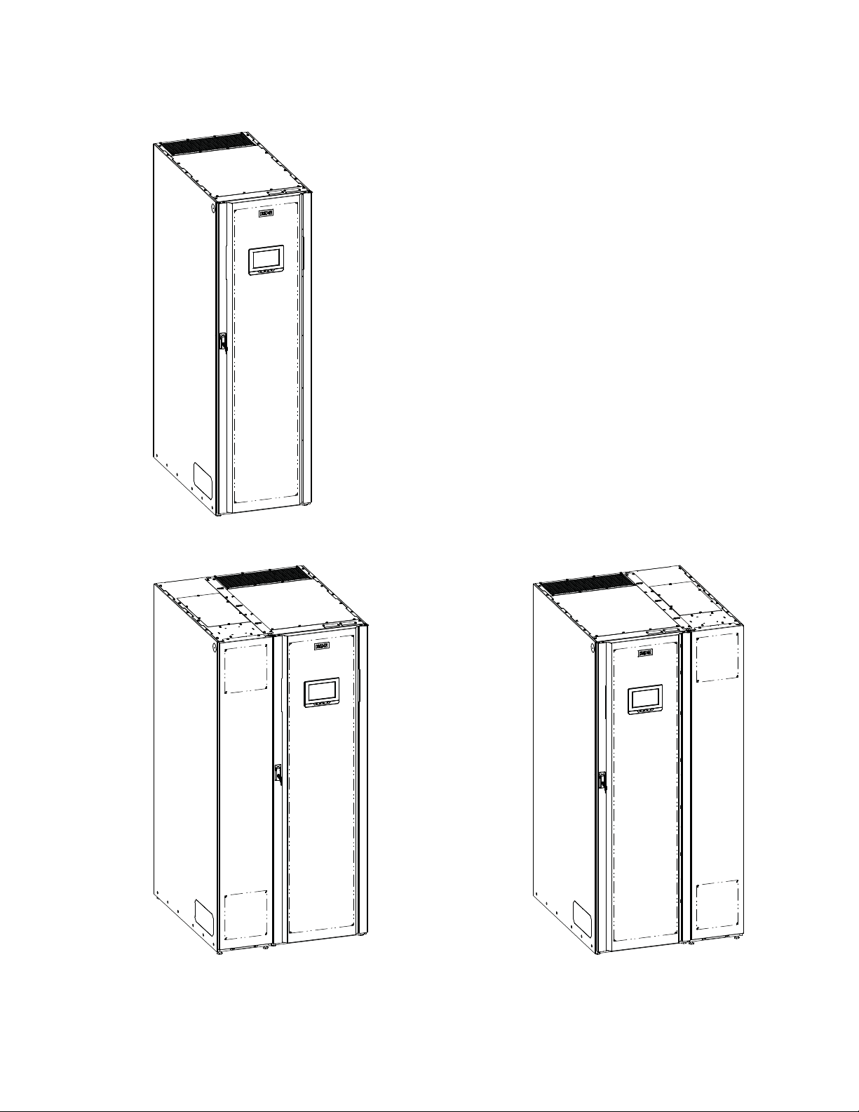
The UPS is housed in a single free-standing cabinet, with safety shields behind the door for hazardous voltage
protection. Power wiring is installed through the bottom of the cabinet with an optional sidecar available for top
entry wiring. Figure 1-1 shows the Eaton 93PM-L 120 kW, Four Wire UPS and Figure 1-2 shows the Eaton
93PM-L 120 kW, Four Wire UPS with a left or right mounted top entry wiring sidecar.
NOTE Startup and operational checks must be performed by an authorized Eaton
1.1 UPS Standard Features
The UPS has many standard features that provide cost-effective and consistently reliable power protection. The
descriptions in this section provide a brief overview of the UPS standard features.
1.1.1 Installation Features
l
Line-up-and-match or standalone configurations
l
Power wiring can be routed through the bottom of the UPS cabinet in standalone configurations or
alternately through the top when configured with an optional accessory sidecar
l
Battery wiring can be run internally through the left or right sides of the UPS cabinet in line-up-and-match
configurations
l
Easily accessible mechanical terminals located at the bottom front of the cabinet reduce installation time
l
Control wiring can be routed through the top or bottom of the UPS cabinet, or through the left or right sides
of the UPS cabinet in line-up-and-match configurations
l
Built-in casters for easy cabinet placement
l
Cabinet bolt holes are provided for permanently mounting the UPS using Eaton’s optional front and rear floor
mounting bracket kit. Side cabinet bolt holes are provided for permanently mounting the UPS using the
customer supplied side mounting brackets and hardware.
Customer Service Engineer, or the warranty terms specified on page W-1 become
void. This service is offered as part of the sales contract for the UPS. Contact an
Eaton service representative in advance (a minimum two-week notice is required) to
reserve a preferred startup date.
Eaton 93PM-L UPS (20–120 kW, 208V) Installation and Operation Manual P-164000688—Rev 02 www.eaton.com/powerquality 1-1
Introduction
UPS with Left-Mounted Sidecar UPS with Right-Mounted Sidecar
Figure 1-1. Eaton 93PM-L UPS (120 kW, Four Wire)
Figure 1-2. Eaton 93PM-L UPS (120 kW, Four Wire) with Left or Right Mounted Top Entry Wiring Sidecar
1-2 Eaton 93PM-L UPS (20–120 kW, 208V) Installation and Operation Manual P-164000688—Rev 02 www.eaton.com/powerquality

Introduction
1.1.2 Control Panel
The control panel, located on the front of the UPS, contains a color liquid crystal touch screen display (LCD) and
a horizontal row of LED indicators to control the operation of the UPS and to display the status of the UPS
system. See Chapter 6, “UPS Operating Instructions,” for additional information.
1.1.3 Customer Interface
l
Building Alarm Monitoring – Up to five inputs in the UPS are available to connect the facility's alarm
system contacts. Some system configurations may limit the number of inputs available. The UPS uses
these inputs to monitor the building alarms in addition to the UPS status. See Chapter 7, “Communication,”
for additional information.
l
Alarm Contact – One alarm contact is provided for connection to equipment at the facility, such as a light,
an audible alarm, or a computer terminal. The equipment connected to this contact alerts you to a UPS
alarm. See Chapter 7, “Communication,” for additional information.
l
Minislot Communication Bays – Four communication bays are standard equipment. One to four optional
Minislot® connectivity cards can be installed in the UPS at any time. Minislot cards are quickly installed at
the front of the UPS and are hot-pluggable. See Chapter 7, “Communication,” for additional information.
1.1.4 Energy Saver System Mode
The 93PM-L Series UPS offers an Energy Saver System (ESS) mode that maximizes efficiency by eliminating
unnecessary power conversion when the commercial power source is within acceptable voltage and frequency
limits. In this mode, the UPS is actively monitoring the critical bus and instantly and seamlessly transitions to
double-conversion mode (inverter online) if a commercial electrical power brownout, blackout, overvoltage,
undervoltage, or out-of-tolerance frequency condition occurs. See Chapter 6, “UPS Operating Instructions,” for
additional information.
1.1.5 Internal Redundancy
To deliver greater reliability, the Eaton 93PM-L UPS can be configured for internal redundancy. When
configured, the UPS automatically becomes redundant if the load is at or below the capacity of the UPMs minus
the capacity of one UPM. Under normal conditions the UPMs in the UPS share the load equally. If one or more
UPMs becomes unavailable and the load is at or below the capacity of remaining UPMs, the remaining UPMs
supply the load instead of transferring to bypass.
1.1.6 Advanced Battery Management
Advanced Battery Management (ABM) technology uses sophisticated sensing circuitry and a three-stage
charger. The charger is a high-frequency, IGBT-based power conversion stage that extends the useful service
life of UPS batteries by isolating the battery from the electrical environment, except for periodic charging or
reserve mode operation. ABM also protects batteries from damage due to high current charging and inverter
ripple currents. Charging at high currents can overheat and damage batteries.
ABM extends battery life by keeping the batteries charged and performing periodic battery testing. The battery
test checks the batteries by transferring to battery mode. During the test the battery voltage is constantly
monitored to determine Battery Health. ABM is intended for VRLA style batteries.
An ABM charging cycle starts with the charger driving the battery voltage at maximum current limit, to a battery
charge level of 2.30volts/cell. The time it takes for the voltage to reach to the battery charge level is saved as
the battery charge time. If the battery charge time exceeds 24 hours, an alarm sounds.
When the battery reaches the float level, the battery is charged at the float level for 48 hours. Due to charger
capability, some battery cabinet configurations extend float level to 72 hours. Twenty-four hours into the float
period, a series of battery tests are performed to check the battery health. The float level charge continues after
a successful test.
Eaton 93PM-L UPS (20–120 kW, 208V) Installation and Operation Manual P-164000688—Rev 02 www.eaton.com/powerquality 1-3

Introduction
After initial startup, the battery run time on the front panel display indicates two minutes. After the 24-hour float
charging period and automated battery testing, the actual battery run time is determined and the actual battery
run time is displayed.
After the float period is completed, the charger is disconnected and the batteries are allowed to rest for 672
hours (28 days) maximum rest time. If the battery voltage falls below the opportunity charge level of 2.1V/cell
during the first 240 hours (10 days) of the rest period, an alarm sounds.
An ABM charge cycle is initiated whenever one of these four conditions occurs since the last charge cycle:
l
The batteries have rested over the maximum rest time of 672 hours.
l
Accumulated discharge time is over a maximum battery discharge time of 20 seconds.
l
Battery voltage is under the opportunity charge level of 2.1 volts/cell and the cabinet has been in rest mode
for longer than 240 hours.
l
A SHUT command or manual front display command Initiates Battery Test.
1.2 Options and Accessories
Contact an Eaton sales representative for information about the following options.
1.2.1 Integrated Battery Cabinet
Battery backup protection with additional runtime can be provided by equipping the UPS system with up to four
Integrated Battery Cabinets (IBCs) containing sealed lead-acid, maintenance-free batteries. The IBCs are
housed in single, free-standing cabinets designed for line-up-and-match installation, but may be installed
separate from the UPS cabinet. The IBCs may be installed on either the right or left side of the UPS cabinet.
NOTE The recommended installation location for adjacent battery cabinets is on the
opposite side of the UPS when SIAC-B is present.
1.2.2 Sidecar Integrated Accessory Cabinet-Bypass
A Sidecar Integrated Accessory Cabinet-Bypass (SIAC-B) provides maintenance bypass functions. The SIAC-B
is available in two, three, or four breaker configurations enabling power to completely bypass the UPS. The UPS
can then be safely serviced or replaced without interrupting power to critical systems. Our manufacturing
facility installs the SIAC-B on either the right or left side of the UPS cabinet based on the order requirements.
The SIAC-B can also be used for top entry wiring access.
1.2.3 Top Entry Wiring Sidecar
If required, a sidecar is available for top entry power wiring. The sidecar performs the function of a wireway
routing the wires to the terminals mounted at the bottom of the UPS cabinet. Our manufacturing facility installs
the sidecar can be installed on the left or right side of the UPS cabinet based on the order requirements.
1-4 Eaton 93PM-L UPS (20–120 kW, 208V) Installation and Operation Manual P-164000688—Rev 02 www.eaton.com/powerquality

Introduction
1.2.4 Monitoring and Communication
Minislot Cards – Optional Minislot cards support several protocols, such as SNMP, SMTP, HTTP, Modbus®,
and TCP/IP. See Chapter 7, “Communication,“ for additional information on monitoring and communication
features.
Remote Monitoring Device (RMD) – An optional RMD contains a touch screen status display and a local
audible alarm, allowing monitoring of the operational status and alarm condition of the UPS from virtually any
location within the facility, up to 300 feet from the UPS. Refer to the Eaton 93PM Remote Monitoring Device
(RMD) Installation and Operation Manual, listed in paragraph 1.8, for additional information.
PredictPulse™ Remote Monitoring and Management Service – PredictPulse is a subscription monitoring
and management service from Eaton that collects and analyzes data from connected power infrastructure
devices, providing us with the insight needed to make recommendations and take action on your behalf. It’s
also powered by CA Technologies, bringing together the best in hardware and software. Like a second set of
eyes on your power infrastructure, PredictPulse provides 24/7 remote monitoring of alarms and system
performance (load, temperature/humidity, battery health, energy savings and service level) to reduce downtime
risk and expedite repairs. PredictPulse also shares real-time status and trend information via an online
dashboard and smartphone mobile app (Apple and Android), giving subscribers insights about past and current
performance, a list of all active alarms, and asset management data (i.e., battery date codes, last and next
scheduled service dates, firmware versions). The service notifies customers of critical alarms, supports remote
diagnostics, and facilitates smart dispatch of technicians. PredictPulse requires a Power Xpert
Minislot (PXGMS) connectivity card in an Minislot communication bay andan Environmental Monitoring Probe
(EMP) for battery temperature/humidity monitoring. See Chapter 7, “Communication,“ for additional
information on monitoring and communication features.
®
Gateway
1.2.5 Additional Output Surge Protection
The Eaton 93PM-L UPS complies with ANSI 62.41 for line surges. However, if added security is required an
additional Surge Protection Device (SPD) can be installed. For this application, a 208V Delta Style SPD Type 1
or Type 2 installed on the load side is recommended. The SPD must meet the Maximum Continuous Operating
Voltage (MCOV) for a 208V Delta Style SPD. Eaton offers a variety of SPD solutions including the Eaton SPD
Series with various kA ratings options.
1.3 Battery System
Although not provided with the UPS, a battery system is required to provide emergency short-term backup
power to safeguard operation during brownouts, blackouts, and other power interruptions. The battery system
should be equipped with lead-acid batteries. An external battery disconnect switch or tie point must be used
when battery systems are located separate from the UPS cabinet and wiring exceeds the number of battery
terminals available.
A supplemental 48 Vdc shunt trip signal for the battery disconnect device is provided by the UPS, but is not
required for normal operation.
1.4 Basic System Configurations
The following basic UPS system configurations are possible:
l
Single UPS (20–120 kW) with one to four external battery cabinets
l
Single UPS (20–120 kW) with one to four external battery cabinets and accessory cabinets
The UPS system configuration can be enhanced by adding optional accessories such as a Remote Emergency
Power-off (REPO) control or Minislot communication cards.
Eaton 93PM-L UPS (20–120 kW, 208V) Installation and Operation Manual P-164000688—Rev 02 www.eaton.com/powerquality 1-5

Introduction
1.5 Using This Manual
This manual describes how to install and operate the Eaton 93PM-L 120 kW, Four Wire UPS. Read and
understand the procedures described in this manual to ensure trouble-free installation and operation. In
particular, be thoroughly familiar with the REPO procedure (see paragraph 6.3.16) or the LOAD OFF procedure
(see paragraph 6.3.15).
The information in this manual is divided into sections and chapters. The system, options, and accessories
being installed dictate which parts of this manual should be read. At a minimum, Chapters 1 through 4
and Chapter 6 should be examined.
Read through each procedure before beginning the procedure. Perform only those procedures that apply to the
UPS system being installed or operated.
1.6 Conventions Used in This Manual
This manual uses these type conventions:
l
Bold type highlights important concepts in discussions, key terms in procedures, and menu options, or
represents a command or option that you type or enter at a prompt.
l
Italic type highlights notes and new terms where they are defined.
l
Screen type represents information that appears on the screen or LCD.
Icon Description
Note Information notes call attention to important features or instructions.
[Keys] Brackets are used when referring to a specific key, such as [Enter] or [Ctrl].
In this manual, the term UPS refers only to the UPS cabinet and its internal elements. The term UPS system
refers to the entire power protection system – the UPS cabinet, an external battery system, and options or
accessories installed.
The term line-up-and-match refers to accessory cabinets that are physically located adjacent to the UPS. The
term standalone refers to accessory cabinets that are located separate from the UPS.
Left and right side notations are referenced standing in front of the cabinet.
1-6 Eaton 93PM-L UPS (20–120 kW, 208V) Installation and Operation Manual P-164000688—Rev 02 www.eaton.com/powerquality
1.7 Symbols, Controls, and Indicators
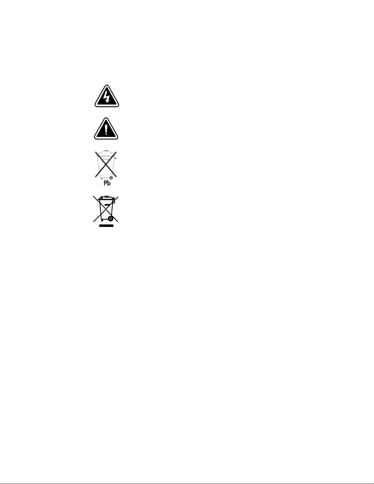
The following are examples of symbols used on the UPS or accessories to alert you to important information:
RISK OF ELECTRIC SHOCK - Observe the warning associated with the risk
of electric shock symbol.
CAUTION: REFER TO OPERATOR'S MANUAL - Refer to your operator's
manual for additional information, such as important operating and
maintenance instructions.
This symbol indicates that you should not discard the UPS or the UPS
batteries in the trash. This product contains sealed, lead-acid batteries and
must be disposed of properly. For more information, contact your local
recycling/reuse or hazardous waste center.
Introduction
1.8 For More Information
Refer to the Eaton 93PM Integrated Battery Cabinet Installation Manual-Small Welded or the Eaton 93PM
Universal Integrated Battery Cabinet Installation Manual-Large and Large High Rate for the following additional
information:
l
Installation instructions, including site preparation, planning for installation, wiring and safety information,
and detailed illustrations of cabinets with dimensional and connection point drawings
l
Operation, including breakers, standard features and optional accessories, procedures for using the bypass
functions, and information about maintenance
Refer to the Eaton 93PM Remote Monitoring Device (RMD) Installation and Operation Manual for additional
installation and operating instructions.
l
Visit www.eaton.com/powerquality or contact an Eaton service representative for information on how to
obtain copies of these manuals.
1.9 Getting Help
If help is needed with any of the following:
l
Scheduling initial startup
l
Regional locations and telephone numbers
l
A question about any of the information in this manual
l
A question this manual does not answer
This symbol indicates that you should not discard waste electrical or
electronic equipment (WEEE) in the trash. For proper disposal, contact your
local recycling/reuse or hazardous waste center.
Eaton 93PM-L UPS (20–120 kW, 208V) Installation and Operation Manual P-164000688—Rev 02 www.eaton.com/powerquality 1-7

Introduction
Please call the Customer Reliability Center at:
United States: 1-800-843-9433
Canada: 1-800-461-9166 ext 260
All other countries: Call your local service representative
Please use the following e-mail address for manual comments, suggestions, or to report an error in this manual:
E-ESSDocumentation@eaton.com
1-8 Eaton 93PM-L UPS (20–120 kW, 208V) Installation and Operation Manual P-164000688—Rev 02 www.eaton.com/powerquality

Chapter 2 Safety Warnings
IMPORTANT SAFETY INSTRUCTIONS SAVE THESE INSTRUCTIONS
DANGER
WARNING
This manual contains important instructions that should be followed during installation and
maintenance of the UPS and batteries. Read all instructions before operating the equipment and
save this manual for future reference.
The UPS is designed for industrial or computer room applications, and contains safety shields
behind the door and front panels. However, the UPS is a sophisticated power system and should
be handled with appropriate care.
This UPS contains LETHAL VOLTAGES. All repairs and service should be performed by
AUTHORIZED SERVICE PERSONNEL ONLY. There are NO USER SERVICEABLE PARTS inside the
UPS.
l
The UPS is powered by its own energy source (batteries). The output terminals may carry live
voltage even when the UPS is disconnected from an AC source.
l
To reduce the risk of fire or electric shock, install this UPS in a temperature and humidity
controlled, indoor environment, free of conductive contaminants. Ambient temperature must
not exceed 40C (104F). Do not operate near water or excessive humidity (95% maximum).
The system is not intended for outdoor use.
l
As a result of the connected loads high leakage current is possible. Connection to earth ground
is required for safety and proper product operation. Do not check UPS operation by any action
that includes removal of the earth (ground) connection with loads attached.
l
Emergency Power Off (EPO) and Remote Emergency Power Off (REPO) functionality is disabled
for UPS systems configured for UL 924 auxiliary lighting. To remove power from the system a
LOAD OFF command (see paragraph 6.3.15) must be given using the front panel controls and all
breakers opened.
l
Ensure all power is disconnected before performing installation or service.
l
Batteries can present a risk of electrical shock or burn from high short-circuit current. The
following precautions should be observed: 1) Remove watches, rings, or other metal objects;
2) Use tools with insulated handles; 3) Do not lay tools or metal parts on top of batteries;
4) Wear rubber gloves and boots.
l
ELECTRIC ENERGY HAZARD. Do not attempt to alter any UPS or battery wiring or connectors.
Attempting to alter wiring can cause injury.
l
Do not open or mutilate batteries. Released electrolyte is harmful to the skin and eyes. It may
be toxic.
Eaton 93PM-L UPS (20–120 kW, 208V) Installation and Operation Manual P-164000688—Rev 02 www.eaton.com/powerquality 2-1

Safety Warnings
CAUTION
AVERTISSEMENT!
ATTENTION!
l
Installation or servicing should be performed by qualified service personnel knowledgeable of
UPS and battery systems, and required precautions. Keep unauthorized personnel away from
equipment. Consider all warnings, cautions, and notes before installing or servicing equipment.
DO NOT DISCONNECT the batteries while the UPS is in Battery mode.
l
Replace batteries with the same number and type of batteries as originally installed with the
UPS.
l
Disconnect the charging source prior to connecting or disconnecting terminals.
l
Determine if the battery is inadvertently grounded. If it is, remove the source of the ground.
Contacting any part of a grounded battery can cause a risk of electric shock. An electric shock is
less likely if you disconnect the grounding connection before you work on the batteries.
l
Proper disposal of batteries is required. Refer to local codes for disposal requirements.
l
Do not dispose of batteries in a fire. Batteries may explode when exposed to flame.
l
Keep the UPS door closed and front panels installed to ensure proper cooling airflow and to
protect personnel from dangerous voltages inside the unit.
l
Do not install or operate the UPS system close to gas or electric heat sources.
l
Lead-acid batteries can present a risk of fire because they generate hydrogen gas. Do not
smoke when near batteries. Do not cause flame or spark in battery area. Discharge static
electricity from body before touching batteries by first touching a grounded metal surface.
l
The operating environment should be maintained within the parameters stated in this manual.
l
Keep surroundings uncluttered, clean, and free from excess moisture.
l
Observe all DANGER, CAUTION, and WARNING notices affixed to the inside and outside of the
equipment.
l
Les batteries peuvent présenter un risque de décharge électrique ou de brûlure par des
courts–circuits de haute intensité. Prendre les précautions nécessaires.
l
Pour le replacement, utiliser le même nombre et modéle des batteries.
l
Une mise au rebut réglementaire des batteries est obligatoire. Consulter les règlements en
vigueur dans votre localité.
l
Ne jamais jeter les batteries au feu. L'exposition aux flammes risque de les faire exploser.
l
Les accumulateurs au plomb-acide peuvent représenter un risque d’incendie, car ils génèrent
de l’hydrogène gazeux. Ne pas fumer près des accumulateurs. Ne pas produire de flamme ou
d’étincelle dans la zone de l’accumulateur. Dissiper l'électricité statique de votre corps en
touchant une surface reliée à la terre avant de toucher les accumulateurs.
2-2 Eaton 93PM-L UPS (20–120 kW, 208V) Installation and Operation Manual P-164000688—Rev 02 www.eaton.com/powerquality

Chapter 3 UPS Installation Plan and Unpacking
Use the following basic sequence of steps to install the UPS:
1. Create an installation plan for the UPS system (Chapter 3).
2. Prepare your site for the UPS system (Chapter 3).
3. Inspect and unpack the UPS cabinet (Chapter 3).
4. Unload and install the UPS cabinet, and wire the system (Chapter 4).
5. Install features, accessories, or options, as applicable (Chapter 4).
6. Complete the Installation Checklist (Chapter 4).
7. Have authorized service personnel perform preliminary operational checks and start up the system.
NOTE Startup and operational checks must be performed by an authorized Eaton
Customer Service Engineer, or the warranty terms specified on page W-1 become
void. This service is offered as part of the sales contract for the UPS. Contact an
Eaton service representative in advance (a minimum two-week notice is required)
to reserve a preferred startup date.
3.1 Creating an Installation Plan
Before installing the UPS system, read and understand how this manual applies to the system being installed.
Use the procedures and illustrations in paragraph 3.2 and Chapter 4 to create a logical plan for installing the
system.
3.2 Preparing the Site
For the UPS system to operate at peak efficiency, the installation site should meet the environmental
parameters outlined in this manual. The operating environment must meet the weight, clearance, and
environmental requirements specified.
3.2.1 Environmental and Installation Considerations
The UPS system installation must meet the following guidelines:
l
The system must be installed on a level floor suitable for computer or electronic equipment.
l
The system must be operated at an altitude no higher than 1500m (5000 ft) without derating. For additional
assistance with high altitude operation, contact an Eaton service representative (see paragraph 1.9).
l
The system must be installed in a temperature and humidity controlled indoor area free of conductive
contaminants.
l
The environmental requirements specified below are for the air at the intake ports of the 93PM UPS, and are
the maximum, not to exceed, ratings.
- There shall be at least a 1.8°F (1.0°C) difference between the dry bulb temperature and the wet bulb
temperature, at all times, to maintain a non-condensing environment.
- The maximum rate of temperature change shall be limited to 3°F over 5 minutes (36°F/hour), based on
the ASHRAE Standard 90.1-2013.
Eaton 93PM-L UPS (20–120 kW, 208V) Installation and Operation Manual P-164000688—Rev 02 www.eaton.com/powerquality 3-1

UPS Installation Plan and Unpacking
CAUTION
l
The newer, more energy efficient data center cooling methods (such as air side economization) can create
much wider ranges of temperature and Relative Humidity (RH) in the UPS room and/or data center. There
are two aspects of this increased operating environment that can, if ignored, create issues.
- One is the creation of microclimates, which are persistent variations of temperature and/or RH within a
single room. For example one side of the room is always cooler than the other side, no matter the actual
temperature.
- The other aspect is the rate of change of temperature and/or RH, which can occur during transitions
within the cooling system. Examples: changing the mixture ratio of inside versus outside air, or external
changes in the outside air when going from night to day, and back to night.
- When ignored, either one of these aspects can create an undesirable microclimate at the UPS location. If
the environment created by this microclimate exceeds the UPS operating specification, the UPS reliability,
over time, will be reduced. These same environmental extremes will also create reliability concerns for
any servers that are exposed to them.
Failure to follow guidelines may void your warranty.
The basic environmental requirements for operation of the UPS are:
l
Ambient Temperature Range: 5–40C (41–104F)
l
Recommended Operating Range: 5–40C (41–104F)
l
Maximum Relative Humidity: 95%, noncondensing
If battery systems are located in the same room as the UPS, the battery manufacturer's
environmental requirements should be followed if they are more stringent than the UPS
requirements. Operating temperatures above the recommended range will result in decreased
battery life and performance, and may reduce or void the battery warranty.
3-2 Eaton 93PM-L UPS (20–120 kW, 208V) Installation and Operation Manual P-164000688—Rev 02 www.eaton.com/powerquality

UPS Installation Plan and Unpacking
The UPS ventilation requirements are shown in Table 3-1. To allow for future power upgrades, Eaton
recommends using air conditioning or ventilation sized for the fully rated UPS kW frame size installed instead
of the derated kW ordered. Sizing the site cooling infrastructure to be capable of cooling the maximum kW
frame size will allow a full power rating upgrade without having to modify the infrastructure.
Table 3-1. Air Conditioning or Ventilation Requirements During Full Load Operation
Heat Rejection
Model UPS Rating
Eaton 93PM-L 120-1
Eaton 93PM-L 120-2 (N+1)
Eaton 93PM-L 120-2
Eaton 93PM-L 120-3 (N+1)
Eaton 93PM-L 120-3
Eaton 93PM-L 120-4 (N+1)
Eaton 93PM-L 120-4
Eaton 93PM-L 120-5 (N+1)
Eaton 93PM-L 120-5
Eaton 93PM-L 120-6 (N+1)
Eaton 93PM-L 120-6 120 kW 29,355 (7401) 543 liter/sec (1150 cfm)
20 kW 4891 (1233)
40 kW 9782 (2467)
60 kW 14,673 (3700)
80 kW 19,563 (4934)
100 kW 24,454 (6167)
BTU/hr (kg-cal/hr)
Minimum Required
Cooling Air Flow
189 liter/sec (400 cfm)
260 liter/sec (550 cfm)
260 liter/sec (550 cfm)
330 liter/sec (700 cfm)
330 liter/sec (700 cfm)
401 liter/sec (850 cfm)
401 liter/sec (850 cfm)
471 liter/sec (1000 cfm)
471 liter/sec (1000 cfm)
543 liter/sec (1150 cfm)
Eaton 93PM-L UPS (20–120 kW, 208V) Installation and Operation Manual P-164000688—Rev 02 www.eaton.com/powerquality 3-3

UPS Installation Plan and Unpacking
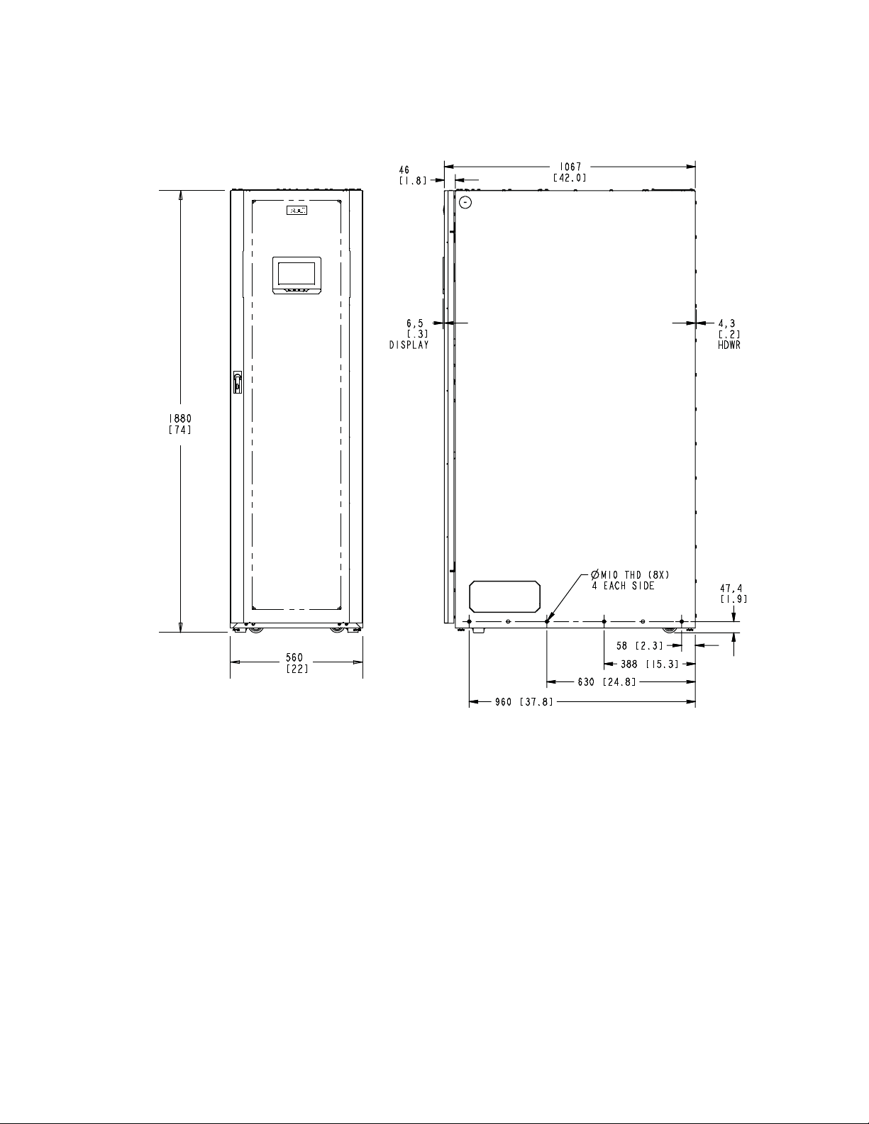
The UPS equipment operating environment must meet the weight requirements shown in Table 3-2 and the
size requirements shown in Figure 3-1 through Figure 3-9. Dimensions are in millimeters (inches).
Table 3-2. UPS Cabinet Weights
Weight
kg (lb)
Model
Eaton 93PM-L 120 with 1 UPM Installed 349 (769) 318 (702) 4 at 80 (176)
Eaton 93PM-L 120 with 2 UPMs Installed 381 (838) 350 (771) 4 at 88 (193)
Eaton 93PM-L 120 with 3 UPMs Installed 412 (907) 381 (840) 4 at 95 (210)
Eaton 93PM-L 120 with 4 UPMs Installed 443 (976) 412 (909) 4 at 103 (227)
Eaton 93PM-L 120 with 5 UPMs Installed 475 (1045) 444 (978) 4 at 111 (245)
Eaton 93PM-L 120 with 6 UPMs Installed 506 (1114) 475 (1047) 4 at 119 (262)
Eaton 93PM-L 120 with 1 UPM Installed - Left-Mounted or Right-Mounted Top Entry Wiring Sidecar (no breakers) 457 (1007) 426 (940) 6 at 71 (157)
Eaton 93PM-L 120 with 2 UPMs Installed - Left-Mounted or Right-Mounted Top Entry Wiring Sidecar (no
breakers)
Eaton 93PM-L 120 with 3 UPMs Installed - Left-Mounted or Right-Mounted Top Entry Wiring Sidecar (no
breakers)
Eaton 93PM-L 120 with 4 UPMs Installed - Left-Mounted or Right-Mounted Top Entry Wiring Sidecar (no
breakers)
Eaton 93PM-L 120 with 5 UPMs Installed - Left-Mounted or Right-Mounted Top Entry Wiring Sidecar (no
breakers)
Eaton 93PM-L 120 with 6 UPMs Installed - Left-Mounted or Right-Mounted Top Entry Wiring Sidecar (no
breakers)
Eaton 93PM-L 120 UPS with 1 UPM Installed - Left-Mounted or Right-Mounted 4-Breaker SIAC-B 590 (1299) 559 (1232) 6 at 93 (205)
Eaton 93PM-L 120 UPS with 2 UPMs Installed - Left-Mounted or Right-Mounted 4-Breaker SIAC-B 621 (1368) 590 (1301) 6 at 98 (217)
Eaton 93PM-L 120 UPS with 3 UPMs Installed - Left-Mounted or Right-Mounted 4-Breaker SIAC-B 652 (1437) 621 (1370) 6 at 104 (228)
Eaton 93PM-L 120 UPS with 4 UPMs Installed - Left-Mounted or Right-Mounted 4-Breaker SIAC-B 684 (1506) 653 (1439) 6 at 109 (240)
Eaton 93PM-L 120 UPS with 5 UPMs Installed - Left-Mounted or Right-Mounted 4-Breaker SIAC-B 715 (1575) 684 (1508) 6 at 114 (251)
Eaton 93PM-L 120 UPS with 6 UPMs Installed - Left-Mounted or Right-Mounted 4-Breaker SIAC-B 746 (1644) 715 (1577) 6 at 119 (263)
Shipping Installed Point Loading
489 (1076) 458 (1009) 6 at 76 (168)
520 (1145) 489 (1078) 6 at 82 (180)
551 (1214) 520 (1147) 6 at 87 (191)
583 (1283) 552 (1216) 6 at 92 (203)
614 (1352) 583 (1285) 6 at 97 (214)
3-4 Eaton 93PM-L UPS (20–120 kW, 208V) Installation and Operation Manual P-164000688—Rev 02 www.eaton.com/powerquality

UPS Installation Plan and Unpacking
The UPS cabinet uses forced air cooling to regulate internal component temperature. Air inlets are in the front
of the cabinet and outlets are on top or in the back of the cabinet. Allow clearance in front of and on top or in
back of the cabinet for proper air circulation. The clearances required around the UPS cabinet are shown in
Table 3-3.
Table 3-3. UPS Cabinet Clearances
From Front of Cabinet 914 mm (36") working space
From Top of Cabinet 457mm (18.0”)
From Top of Cabinet with Top Exhaust 457 mm (18") minimum clearance for ventilation
From Back of Cabinet with Rear Exhaust 457 mm (18") minimum clearance for ventilation
From Back of Cabinet with Top Exhaust None Required
From Right Side of Cabinet None Required
From Left Side of Cabinet None Required
Eaton 93PM-L UPS (20–120 kW, 208V) Installation and Operation Manual P-164000688—Rev 02 www.eaton.com/powerquality 3-5
UPS Installation Plan and Unpacking
Dimensions are in millimeters [inches]
Front
Right Side
Figure 3-1. UPS Cabinet Dimensions (Front and Right Side Views)
3-6 Eaton 93PM-L UPS (20–120 kW, 208V) Installation and Operation Manual P-164000688—Rev 02 www.eaton.com/powerquality
UPS Installation Plan and Unpacking
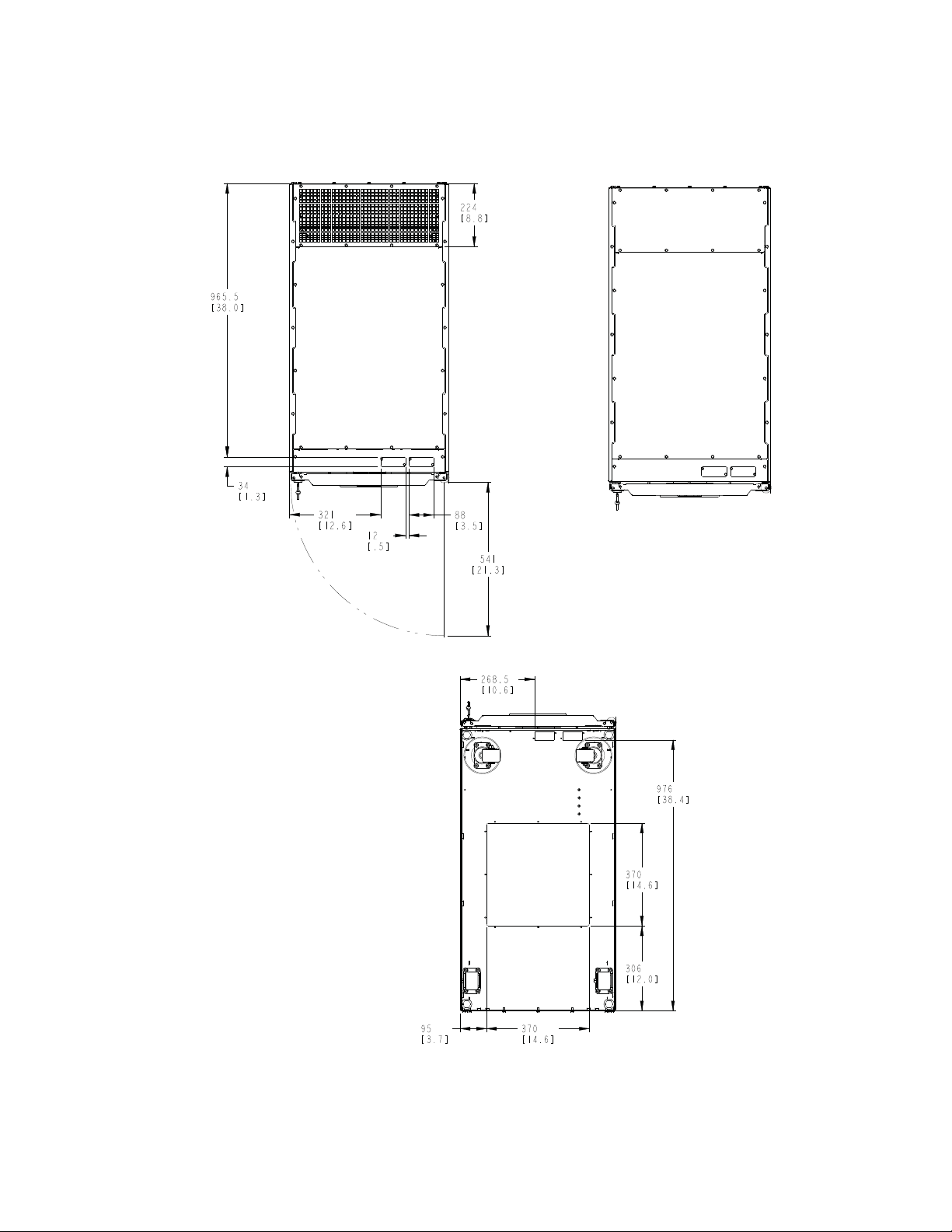
Bottom
Dimensions are in millimeters [inches]
NOTE Top exhaust
configuration shown.
Front
Front
Front
Top
NOTE Rear exhaust
configuration shown.
Top
Figure 3-2. UPS Cabinet Dimensions (Top and Bottom Views)
Eaton 93PM-L UPS (20–120 kW, 208V) Installation and Operation Manual P-164000688—Rev 02 www.eaton.com/powerquality 3-7
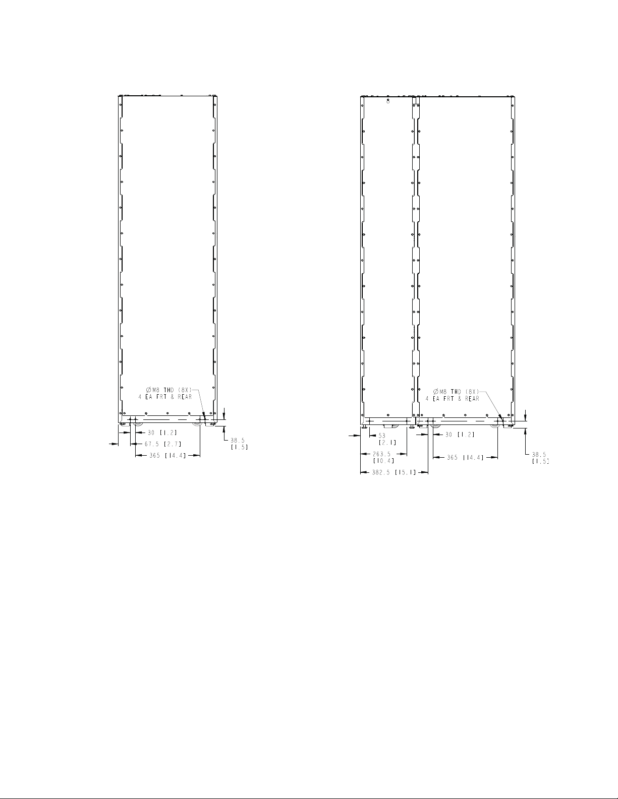
UPS Installation Plan and Unpacking
UPS with SidecarUPS
Mounting Bracket dimensions.
Note: Units are shown
with top exhaust option.
Figure 3-3. UPS Cabinet Rear Floor Mounting Bracket Mounting Dimensions
3-8 Eaton 93PM-L UPS (20–120 kW, 208V) Installation and Operation Manual P-164000688—Rev 02 www.eaton.com/powerquality
 Loading...