

Eaton 93PM IBC-LW, 93PM IBC-LHW Installation Manual

Eaton®®93PM Universal Integrated Battery Cabinet
IBC-LW [Large] (432V and 480V)
IBC-LHW [Large High Rate] (432V and 480V)
Installation Manual
p/n: P-164000541
Revision 04

IMPORTANT SAFETY INSTRUCTIONS SAVE THESE INSTRUCTIONS
!
This manual contains important instructions that should be followed during installation and
maintenance of the UPS and batteries. Read all instructions before operating the equipment and save
this manual for future reference.
CONSIGNES DE SÉCURITÉ IMPORTANTES — CONSERVER CES INSTRUCTIONS
Ce manuel comporte des instructions importantes que vous êtes invité à suivre lors de toute
procédure d'installation et de maintenance des batteries et de l'onduleur. Veuillez consulter
entièrement ces instructions avant de faire fonctionner l'équipement et conserver ce manuel afin de
pouvoir vous y reporter ultérieurement.
IMPORTANT
To ensure you have the most up-to-date content and information for this product, please review the
latest manual revision on our website, www.eaton.com/93PM.
Eaton reserves the right to change specifications without prior notice. Modbus is a registered trademark of Schneider Automation, Inc.
MOXA is a registered trademark and MGate is a trademark of MOXA, Inc. Spiralock is a registered trademark of Spiralock Corporation.
KIRK is a registered trademark of Kirk Key Interlock company, LLC, a subsidiary of Halma plc. National Electrical Code and NEC are
registered trademarks of National Fire Protection Association, Inc. ERIFLEX and FLEXIBAR are registered trademark of Erico International
Corporation. All other trademarks are property of their respective companies.
©Copyright 2016-2019 Eaton, Raleigh, NC, USA. All rights reserved. No part of this document may be reproduced in any way without the
express written approval of Eaton.

EATON
END-USER LICENSE AGREEMENT
IMPORTANT, READ CAREFULLY. THIS END USER LICENSE AGREEMENT (THE
“AGREEMENT”) IS A BINDING CONTRACT BETWEEN YOU, THE END-USER (THE
“LICENSEE”) AND EATON INTELLIGENT POWER LIMITED, IRELAND, OR ONE OF ITS
AFFILIATES (“EATON” OR “LICENSOR”). BY OPERATING THIS UNINTERRUPTIBLE
POWER SUPPLY (UPS) PRODUCT INCLUDING SOFTWARE EMBEDDED IN IT
(FIRMWARE), YOU, THE LICENSEE, ARE AGREEING TO BE BOUND BY THE TERMS,
CONDITIONS, AND LIMITATIONS OF THIS AGREEMENT. READ THE TERMS AND
CONDITIONS OF THIS AGREEMENT CAREFULLY BEFORE, INSTALLING OR OPERATING
THE PRODUCT. IF YOU DO NOT AGREE TO THE TERMS OF THIS AGREEMENT,
PROMPTLY RETURN THE UNUSED PRODUCT TO EATON.
1.0 DEFINITIONS
1.1 Documentation. “Documentation” means the user guides and manuals for the installation
and use of the UPS, whether made available over the internet, provided in CD-ROM, DVD,
hard copy or other form.
1.2 Firmware. “Firmware” means software programs that are embedded in the product for
which Licensee is granted a license hereunder, the Documentation therefore and, to the extent
available, Updates thereto. The Firmware is licensed hereunder in object code (machinereadable) form only except that certain software programs may include limited portions in
source code (human-readable) form.
1.3 Update. “Update” means a subsequent release of the Firmware, if and when developed by
Eaton. An Update does not include any release, new version, option, or future product, which
Eaton licenses separately.
2.0 FIRMWARE LICENSE
2.1 Ownership. Eaton or its third party licensors retains all title, copyright and other proprietary
rights in, and ownership of the Firmware regardless of the media upon which the original or any
copy may be recorded or xed.
2.2 License Grant. Eaton grants to Licensee a limited, revocable, non-exclusive, non-assignable
license to use the Firmware in conjunction with the operation of the product to which the Firmware
pertains or other products as described by Eaton in the Documentation. Licensee does not
acquire any rights, express or implied, other than those expressly granted in this Agreement.
2.3 Restrictions and Requirements. Licensee will not, nor will it permit others to, modify,
adapt, translate, reverse engineer, decompile, or disassemble the Firmware or any component
thereof (including the Documentation), or create derivative works based on the Firmware
(including the Documentation), except to the extent such foregoing restriction is prohibited by
applicable law or applicable open source license to, and only to, any open source software
component that is incorporated into the Firmware (if any). Copyright laws and international
treaties protect the Firmware, including the Documentation. Unauthorized copying of the
Firmware, the Documentation or any part thereof, is expressly prohibited. For avoidance of
doubt, Eaton does not grant Licensee a license to any of Eaton’s brands, logos, designs, trade
dress, service marks, trademarks, domain names or trade names, in whole or in part.
Licensee agrees to install or allow installation of all corrections of substantial defects, security
patches, minor bug xes and updates, including any enhancements, for the Firmware in
accordance with the instructions and as directed by Eaton.
2.4 Transfer and Assignment Restrictions. Licensee will not sell, resell, assign, lease,
sublicense, encumber, or otherwise transfer its interest in this Agreement or in the Firmware,
or the Documentation in whole or in part, or allow any other person or entity, including any
parent or subsidiary of Licensee or other subsidiary of Licensee’s parent, to copy, distribute,
or otherwise transfer the Firmware without the prior written consent of Eaton. Licensee may
transfer the Firmware directly to a third party only in connection with the sale of the Eaton
product in which it is installed.
3.0 TERMINATION
3.1 Termination. This Agreement and the license granted hereunder automatically terminates
if Licensee breaches any provision of this Agreement. Eaton may terminate this license at any
time with or without cause.
3.2 Effect of Termination. Immediately upon termination of this Agreement or the license
granted hereunder, Licensee will cease using the product. The parties’ rights and obligations
under the following sections of this Agreement will survive termination of this Agreement: Article
1.0, Section 2.1, Section 2.3, Section 2.4, Article 3.0, Article 4.0 and Article 5.0.
4.0 INFRINGEMENT AND WARRANTIES
4.1 Infringement. If Licensee learns of a threat, demand, allegation, or indication that the
UPS with its rmware infringes or misappropriates any third party intellectual property rights
(including but not limited to any patent, copyright, trademark, trade dress, or trade secret)
(“Intellectual Property Claim”), Licensee will notify Eaton promptly of such claim. Eaton may, in
its sole discretion, elect to assume sole control of the defense and settlement of said Intellectual
Property Claim and Licensee will provide reasonable information and assistance to Eaton for
the defense of such claim.
4.2 Disclaimer of Warranties. THE FIRMWARE IS PROVIDED “AS IS” WITHOUT
WARRANTY OF ANY KIND, . EATON DOES NOT WARRANT THAT THE FIRMWARE
WILL BE ERROR-FREE OR SECURE FROM UNAUTHORIZED ACCESS. THE LICENSEE
EXPRESSLY ACKNOWLEDGES THAT TO THE EXTENT PERMITTED BY APPLICABLE
LAW, THE USE OF THE PRODUCT IS AT LICENSEE’S SOLE RISK.
5.0 GENERAL PROVISIONS
5.1 Update Policy. Eaton may from time to time, but has no obligation to, create Updates of
the Firmware or components thereof.
5.2 Limitation on Liability. NOTWITHSTANDING ANY PROVISION OF THIS AGREEMENT
TO THE CONTRARY, LICENSEE EXPRESSLY UNDERSTANDS AND AGREES THAT
EATON, ITS AFFILIATES, AND ITS LICENSORS, WILL NOT BE LIABLE FOR: (A) ANY
DIRECT, INDIRECT, INCIDENTAL, SPECIAL, CONSEQUENTIAL OR EXEMPLARY
DAMAGES WHICH MAY BE INCURRED BY LICENSEE OR ANY THIRD PARTY,
HOWEVER CAUSED AND UNDER ANY THEORY OF LIABILITY. THIS WILL INCLUDE,
BUT NOT BE LIMITED TO, ANY LOSS OF PROFIT (WHETHER INCURRED DIRECTLY OR
INDIRECTLY), ANY LOSS OF GOODWILL OR BUSINESS REPUTATION, ANY LOSS OF
DATA SUFFERED, COST OF PROCUREMENT OF SUBSTITUTE GOODS OR SERVICES,
OR OTHER INTANGIBLE LOSS; (B) ANY LOSS OR DAMAGE WHICH MAY BE INCURRED
BY LICENSEE OR ANY THIRD PARTY. THESE LIMITATIONS ON EATON’S LIABILITY WILL
APPLY WHETHER OR NOT EATON HAS BEEN ADVISED OF OR SHOULD HAVE BEEN
AWARE OF THE POSSIBILITY OF ANY SUCH LOSSES ARISING.
TO THE EXTENT PERMITTED BY LAW, THE TOTAL LIABILITY OF EATON, ITS AFFILIATES,
AND ITS LICENSORS, FOR ANY CLAIMS UNDER THESE TERMS, INCLUDING FOR ANY
IMPLIED WARRANTIES, IS LIMITED TO THE AMOUNT PAID FOR THE UPS.
THIS SECTION 5.2 STATES EATON’S ENTIRE LIABILITY AND LICENSEE’S SOLE AND
EXCLUSIVE REMEDY UNDER THIS AGREEMENT, AND IS SUBJECT TO ALL LIMITATIONS
STATED IN SECTION 4.2.
5.3 Notices. All notices required to be sent hereunder will be in writing and will be deemed to
have been given when mailed by rst class mail to the address shown below:
LICENSE NOTICES:
Eaton Intelligent Power Limited
Eaton House,
30 Pembroke Road,
Dublin 4,
D04 Y0C2,
Ireland
5.4 Severability. If any provision of this Agreement is held to be invalid or unenforceable, the
remaining provisions of this Agreement will remain in full force.
5.5 Waiver. The waiver by either party of any default or breach of this Agreement will not
constitute a waiver of any other or subsequent default or breach. Failure to enforce or delay in
enforcing any provision of this Agreement will not constitute a waiver of any rights under any
provisions of this Agreement.
5.6 Entire Agreement. This Agreement constitutes the complete agreement between the
parties and supersedes all prior or contemporaneous agreements or representations, written
or oral, concerning the subject matter of this Agreement. This Agreement may not be modied
or amended except in a writing specically referencing this Agreement and signed by a duly
authorized representative of each party. No other act, document, usage or custom will be
deemed to amend or modify this Agreement. The Firmware, or portions thereof, may also
be subject to additional paper or electronic license agreements. In such cases, the terms of
this Agreement will be supplemental to those in the additional agreements, to the extent not
inconsistent with the additional agreements. If a copy of this Agreement in a language other
than English is included with the Firmware or Documentation, it is included for convenience and
the English language version of this Agreement will control.
5.7 Heirs, Successors, and Assigns. Each and all of the covenants, terms, provisions
and agreements herein contained will be binding upon and inure to the benet of the parties
hereto and, to the extent expressly permitted by this Agreement, their respective heirs, legal
representatives, successors and assigns.
5.8 Export Restrictions. Licensee agrees to comply fully with all relevant export laws and
regulations of the United States and all other countries in the world (the “Export Laws”) to
assure that neither the Firmware nor any direct product thereof are (I) exported, directly or
indirectly, in violation of Export Laws; or (ii) are intended to be used for any purposes prohibited
by the Export Laws. Without limiting the foregoing, Licensee will not export or re-export the
Firmware: (i) to any country to which the U.S. has embargoed or restricted the export of
goods or services (see http://www.treasury.gov/resource-center/sanctions/Programs/Pages/
Programs.aspx), or to any national of any such country, wherever located, who intends to
transmit or transport the Firmware back to such country; (ii) to any end user who Licensee
knows or has reason to know will utilize the Firmware in the design, development or production
of nuclear, chemical or biological weapons; or (iii) to any end-user who has been prohibited
from participating in U.S. export transactions by any federal agency of the U.S. government.
5.9 U.S. Government Restricted Rights. The Firmware is a “commercial item” as that term
is dened at 48 C.F.R. § 2.101, consisting of “commercial computer software” and “commercial
computer software documentation”, as such terms are used in 48 C.F.R. § 12.212, and is
provided to the U.S. Government only as a commercial end item. Consistent with 48 C.F.R.
§ 12.212 and 48 C.F.R. §§ 227.7202-1 through 227.7202-4, all U.S. Government End Users
acquire the Firmware with only those rights set forth herein. Contractor/manufacturer is Eaton
Corporation, 1000 Eaton Boulevard, Cleveland, Ohio 44122.
5.10 Third Party Intellectual Property Rights. The Firmware may contain components
(including open source software components) that are owned by third parties (“Third Party
Licensors”) and are provided with, incorporated into, or embedded in, the Firmware pursuant to
license arrangements between Eaton and such third parties. Third Party Licensor components
in the Firmware are not licensed or warranted under the terms of this document, but are instead
subject to the Third Party Licensors’ license agreements. Licensee will not modify, delete, or
obfuscate any copyright or other proprietary rights notices of Third Party Licensors contained
in the Firmware.
5.11 Indemnity. Licensee shall defend, indemnify and hold Eaton and its ofcers, directors,
employees, and agents harmless from and against all losses, damages, liabilities, claims,
actions, and associated costs and expenses (including reasonable attorneys’ fees and expenses)
by reason of injury or death to any person or damage to any tangible or intangible property arising
or resulting from the negligence or willful misconduct of the Licensee, its employees, contractors,
or agents, in connection with Licensee’s use of Firmware and Documentation.
Licensee shall be responsible for any breach of this Agreement by its ofcers, directors,
employees, contractors, or agents. Licensee shall defend, indemnify, and hold Eaton and
its ofcers, directors, employees, and agents harmless from and against any and all losses,
damages, liabilities, claims, actions, and associated costs and expenses (including reasonable
attorneys’ fees and expenses) arising out of or in connection with any breach of this Agreement.
5.12 Open Source Software. The Firmware may contain certain components owned by
Eaton that are provided with, incorporated into, linked to, or embedded in the Firmware that are
subject to third party open source licenses (“Eaton Open Source Components”). Eaton Open
Source Components are subject to the open source licenses corresponding to the particular
software component. To the extent there are any conicts between the terms of this Agreement
and any open source license corresponding to Eaton Open Source Components or additional
obligations by such open sources license that are not set forth in this Agreement, the terms of
the open source license will control.
5.13 Condentiality. Licensee acknowledges that condential aspects of the Firmware
(including any proprietary source code) are a trade secret of Eaton, the disclosure of which
would cause substantial harm to Eaton that could not be remedied by the payment of damages
alone and such condential aspects of the Firmware shall not be disclosed to third parties
without the prior written consent of Eaton. Accordingly, Eaton will be entitled to preliminary and
permanent injunctive and other equitable relief for any breach of this Section 5.13.
5.14 Note on JAVA Support. The Firmware may contain support for programs written in JAVA.
JAVA technology is not fault tolerant and is not designed, manufactured, or intended for use or
resale as online control equipment in hazardous environments requiring fail-safe performance,
such as in the operation of nuclear facilities, aircraft navigation or communications systems, air
trafc control, direct life support machines, or weapons systems, in which the failure of JAVA
technology could lead directly to death, personal injury, or severe physical or environmental
damage. EATON DISCLAIMS ALL DAMAGES INCLUDING DIRECT, INDIRECT AND
CONSEQUENTIAL DAMAGES RELATING TO THE FAILURE OF ANY SOFTWARE
INCLUDING JAVA PROGRAMS AND/OR JAVA TECHNOLOGY.
5.15 Governing Law. This Agreement will be interpreted and enforced in accordance with the
laws of Ireland, without regard to choice of law principles. Any claim or suit with respect to this
Agreement shall be brought in the Courts of Ireland, unless mandatory law imposes otherwise.
Eaton EULA
P-110000654-001 Revised: December 21st, 2018


TTaabbllee ooff CCoonntteennttss
11 IInnttrroodduuccttiioonn....................................................................................................................................................................................................................................................................................................11
1.1 Installation Features.. ... ....... ... ............. ... .......... ... ... ....... ... .......... ... ... .......... ... .......... ... .......... ... ... ....... ... ....... 2
1.2 Optional Thermal Sensor .... ... ....... ... ... .......... ... .......... ... ... ....... ... ............. ... ....... ... ... ... ....... ... .......... ... ... ....... .. 3
1.3 Model Configurations . ... ....... ... ... .......... ... .......... ... ... ....... ... ... .......... ... ....... ... ... .......... ... ............. ... ....... ... ... ...3
1.4 Using This Manual .... ... ... .......... ... .......... ... .......... ... ............. ... ....... ... ... .......... ... .......... ... .......... ... ............. ... . 3
1.5 Conventions Used in This Manual ....... ... .......... ... ... ....... ... ............. ... .......... ... ... ....... ... .......... ... ... ....... ... .......... 4
1.6 Symbols, Controls, and Indicators ....... ... .......... ... ... ....... ... ............. ... ....... ... ... .......... ... .......... ... ... ....... ... .......... 4
1.7 For More Information ... ... ... .......... ... ....... ... ... ... ....... ... ............. ... ....... ... ... .......... ... ....... ... ... ... ....... ... ............. . 5
1.8 Getting Help.. ... ....... ... ... .......... ... .......... ... .......... ... ............. ... ....... ... ... .......... ... .......... ... .......... ... ............. ... . 5
1.9 Equipment Registration .... ... .......... ... ............. .......... ... ... .......... ... ....... ... ... .......... ... ............. ... ....... ... ... .......... 6
22 SSaaffeettyy WWaarrnniinnggss........................................................................................................................................................................................................................................................................................ 77
33 IInnssttaallllaattiioonn PPllaann aanndd UUnnppaacckkiinngg ...................................................................................................................................................................................................................................... 1111
3.1 Creating an Installation Plan ...... ... ... .......... ... ....... ... ... .......... ... ............. ... ....... ... ... .......... ... .......... ... .......... ... . 11
3.2 Preparing the Site ......... ... ....... ... ... .......... ... ....... ... ... ... ....... ... ............. ... ....... ... ... .......... ... .......... ... ... ....... ... . 11
3.2.1 Environmental and Installation Considerations ... ... .......... ... ... .......... ............. ... .......... ... ... ....... ... .......... ... ... 11
3.2.2 IBC Power Wiring Preparation .... ... ... ....... ... .......... ... ... ....... ... ............. ... ....... ... ... ... ....... ... .......... ... ... ....... 19
3.2.3 IBC Interface Wiring Preparation ...... ... .......... ... ... ....... ... .......... ... ... ....... ... ... .......... ... .......... ... ... ....... ... ..... 25
3.3 Inspecting and Unpacking the IBC..... ... ... ....... ... .......... ... ... .......... ............. ... .......... ... ... .......... .......... ... ... ....... 26
3.4 Battery Breaker Location .... .......... ... ... .......... ... .......... ... .......... ... ............. ... ....... ... ... .......... ... .......... ... .......... 27
44 IInnssttaallllaattiioonn .................................................................................................................................................................................................................................................................................................. 2299
4.1 Preliminary Installation Information..... .......... ... ... .......... ... .......... ... .......... ... ............. ... ....... ... ... .......... ... ......... 29
4.2 Unloading the IBC Cabinet from the Pallet......... ... .......... ... .......... ... ... ....... ... ............. ... .......... ... ... ....... ... ......... 29
4.3 Installing IBC Power Wiring ... ... ... .......... ... .......... ... .......... ... ... .......... .......... ... ... .......... ... ............. .......... ... ... . 35
4.3.1 Line-Up-and-Match Power Wiring.. ... .......... ... ... ....... ... ............. ... ....... ... ... ... ....... ... .......... ... ... ....... ... ........ 35
4.3.2 Standalone Power Wiring .... ... .......... ... ... ....... ... .......... ... ... .......... ............. ... .......... ... ... .......... .......... ... ... 41
4.4 Battery Breaker Instantaneous Trip Setting .... ... ... .......... ... .......... ... ... ....... ... ............. ... .......... ... ... ....... ... ......... 46
4.5 Installing IBC Interface Wiring .... ... ... .......... ... .......... ... .......... ... ... .......... ............. ... .......... ... .......... ... .......... ... 47
4.5.1 Installing Battery Detect Interface Connections.. ... .......... ... ... ....... ... ............. ... ....... ... ... ... ....... ... .......... ... ... 47
4.5.2 Installing Battery Shunt Trip Interface Connections ...... ... ... ....... ... ............. ... .......... ... .......... ... .......... ... ... .... 52
4.5.3 Installing Thermal Sensor Interface Connections ....... ............. ... .......... ... .......... ... .......... ... ... .......... ............ 53
4.6 Initial Startup ..... .......... ... ... .......... ............. ... .......... ... ... .......... .......... ... ... .......... ... .......... ... .......... ... ... ........ 55
4.7 Completing the Installation Checklist ....... ... .......... ... .......... ... ... .......... .......... ... ... .......... ... ............. .......... ... ... . 55
4.8 Installation Checklist .... ... .......... ... .......... ... .......... ... ............. .......... ... ... .......... ... .......... ... .......... ... ............. .. 55
55 OOnneelliinneess aanndd SScchheemmaattiiccss.......................................................................................................................................................................................................................................................... 5577
5.1 Power Onelines .... ... ....... ... ... .......... ... .......... ... ... ....... ... ............. ... .......... ... ... ....... ... .......... ... ... ....... ... ........ 57
5.2 Interface Onelines ..... ... ....... ... ... ... ....... ... .......... ... ... ....... ... ... .......... ... .......... ... ... ....... ... ............. ... ....... ... ... . 60
5.3 Schematics ... ... ... ....... ... ... .......... ... ....... ... ... .......... ... ............. ... ....... ... ... .......... ... ....... ... ... ... ....... ... ............ 61
Eaton 93PM Universal Integrated Battery Cabinet (IBC-LW and IBC-LHW) Installation Manual P-164000541—Rev 04 v

Table of Contents
66 MMaaiinntteennaannccee.............................................................................................................................................................................................................................................................................................. 6633
6.1 Important Safety Instructions ...... ... .......... ... ... .......... ............. ... .......... ... ... .......... .......... ... ... .......... ... .......... .. 63
6.2 Performing Preventive Maintenance .... ............. ... .......... ... .......... ... .......... ... ... .......... ............. ... .......... ... ........ 63
6.2.1 DAILY Maintenance ..... ............. .......... ... ... .......... ... .......... ... .......... ... ............. .......... ... ... .......... ... ......... 63
6.2.2 PERIODIC Maintenance.. .......... ... ... ....... ... .......... ... ... .......... ............. ... .......... ... ... ....... ... .......... ... ... ....... 63
6.2.3 ANNUAL Maintenance.... .......... ... ... ....... ... .......... ... ... .......... ............. ... .......... ... ... ....... ... .......... ... ... ....... 63
6.2.4 BATTERY Maintenance... .......... ... ... .......... .......... ... ... .......... ... ............. .......... ... ... .......... ... ....... ... ... ....... 63
6.2.5 BATTERY Shelf Life... ... .......... ... .......... ... ... .......... ............. ... .......... ... ............. .......... ... ... .......... ... ......... 64
6.3 Recycling the Used Batteries .... ... ... .......... ... .......... ... ... ....... ... ............. ... ....... ... ... .......... ... .......... ... ... ....... ... . 64
6.4 Maintenance Training . ... ....... ... ... .......... ... .......... ... ... ....... ... ... .......... ... ....... ... ... .......... ... ............. ... ....... ... ... . 64
77 PPrroodduucctt SSppeecciiffiiccaattiioonnss ................................................................................................................................................................................................................................................................ 6655
7.1 Model Numbers . .......... ... ... .......... ... ............. .......... ... ... .......... ... ....... ... ... .......... ... ............. .......... ... ... ........ 65
7.2 Specifications ..... ............. ... ....... ... ... ... ....... ... .......... ... ... ....... ... ............. ... ....... ... ... ... ....... ... .......... ... ... ....... 65
7.2.1 Battery Specifications......... ... ... .......... ... ............. .......... ... ... .......... ... .......... ... .......... ... ............. .......... ... 65
7.2.2 Environmental and Safety Specifications... ... .......... ... ... ....... ... .......... ... ... .......... ............. ... .......... ... ... ....... . 66
88 WWaarrrraannttyy ........................................................................................................................................................................................................................................................................................................ 6677
vi Eaton 93PM Universal Integrated Battery Cabinet (IBC-LW and IBC-LHW) Installation Manual P-164000541—Rev 04

LLiisstt ooff FFiigguurreess
Figure 1. Eaton 93PM IBC-LW or Eaton 93PM IBC-LHW ........ ... .......... ... .......... ... .......... ... ... .......... ............. ... ..... 1
Figure 2. Typical Eaton 93PM UPS and Two Eaton 93PM Universal Integrated Battery Cabinets........ ... .......... ... .......... 2
Figure 3. Eaton 93PM IBC-LW or Eaton 93PM IBC-LHW Dimensions (Front and Right Side Views) .. ............. ... ....... ... 15
Figure 4. Eaton 93PM IBC-LW or Eaton 93PM IBC-LHW Dimensions (Rear Views)..... ... .......... ... ... ....... ... ............. .. 16
Figure 5. Eaton 93PM IBC-LW or Eaton 93PM IBC-LHW Dimensions (Top and Bottom Views). .......... ... ....... ... ... ....... 17
Figure 6. Eaton 93PM IBC-LW or Eaton 93PM IBC-LHW Center of Gravity...... ... .......... ... .......... ... ... .......... ............ 18
Figure 7. Eaton 93PM IBC-LW or Eaton 93PM IBC-LHW as Shipped on Pallet .......... ... ....... ... ... .......... ... .......... ... ... 27
Figure 8. Eaton 93PM IBC-LW or Eaton 93PM IBC-LHW Battery Breaker Location – Front View with Front Door
Removed ... ....... ... ... .......... ... .......... ... ... ....... ... ............. ... ....... ... ... ... ....... ... .......... ... ... ....... ... ........ 28
Figure 9. Removing the Pallet Skids and Supports – Eaton 93PM IBC-LW or Eaton 93PM IBC-LHW .......... ... .......... ... . 31
Figure 10. Line-Up-and-Match Wiring Access Locations... ... ............. .......... ... ... .......... ... ....... ... ... .......... ... ............ 33
Figure 11. Rear Ventilation .... .......... ... ....... ... ... .......... ... ............. ... ....... ... ... .......... ... ....... ... ... .......... ... ............ 34
Figure 12. Top Ventilation.... ....... ... ... .......... ... .......... ... ... ....... ... ............. ... ....... ... ... .......... ... .......... ... ... ....... ... . 34
Figure 13. DC Power Terminal Shield Location ... ............. ... .......... ... ............. .......... ... ... .......... ... .......... ... .......... 36
Figure 14. DC Power Terminal Locations – Eaton 93PM IBC-LW or Eaton 93PM IBC-LHW......... ... ... .......... .......... ... ... 38
Figure 15. DC Power Terminal — Bottom Wiring Entry Terminal Installation ... ... ... .......... ............. ... .......... ... ... ....... . 39
Figure 16. DC Power Terminal Detail – Eaton 93PM IBC-LW or Eaton 93PM IBC-LHW........ ... .......... ... ... .......... ......... 40
Figure 17. DC Power Terminal — Top Wiring Entry Terminal Installation ...... ............. ... .......... ... ... ....... ... .......... ... ... 42
Figure 18. Battery Breaker Mount Screw Location and Mount Lever Location - Eaton 93PM IBC........ ... ... .......... ... ...... 43
Figure 19. DC Power Terminal Shield... ... .......... ............. ... .......... ... .......... ... .......... ... ... .......... ... .......... ... .......... 44
Figure 20. IBC Bottom Entry Conduit and Wire Entry Locations .... ... .......... ... .......... ... ... ....... ... ............. ... .......... ... . 45
Figure 21. IBC Top Entry Conduit and Wire Entry Locations .... ... .......... ... ... ....... ... .......... ... ... .......... ... .......... ... ...... 46
Figure 22. Battery Breaker Instantaneous Trip Setting Dials... ... .......... ............. ... .......... ... ... .......... .......... ... ... ....... 47
Figure 23. Interface Terminal Locations – Eaton 93PM IBC-LW or Eaton 93PM IBC-LHW .. ....... ... ............. ... ....... ... ... . 49
Figure 24. Shunt Trip and Battery Detect Wiring.... ... ....... ... ... .......... ... .......... ... ... ....... ... ............. ... .......... ... ........ 50
Figure 25. Interface Terminal Detail – Eaton 93PM IBC-LW or Eaton 93PM IBC-LHW ....... ... ............. ... ....... ... ... ........ 51
Figure 26. Eaton 93PM IBC-LW Line-Up-and-Match Power Oneline ...... ... ... ....... ... .......... ... ... .......... ... .......... ... ...... 57
Figure 27. Eaton 93PM IBC-LW Standalone Power Online – One or Two Cabinets ......... ... ... .......... ............. ... .......... 58
Figure 28. Eaton 93PM IBC-LW Standalone Power Online – Four Cabinets .... ... ... .......... .......... ... ... .......... ... ............ 58
Figure 29. Eaton 93PM IBC-LHW Line-Up-and-Match Power Oneline . ... ... ....... ... ............. ... ....... ... ... ... ....... ... ......... 59
Figure 30. Eaton 93PM IBC-LHW Standalone Power Online – One Cabinet......... .......... ... ... .......... ... .......... ... .......... 59
Figure 31. Eaton 93PM IBC-LHW Standalone Power Online – Two Cabinets .... ... .......... ... ... ....... ... ............. ... .......... 60
Figure 32. Eaton 93PM Universal Integrated Battery Cabinet Interface Oneline ...... ... .......... ... ............. ... ....... ... ... .... 61
Figure 33. Eaton 93PM Universal Integrated Battery Cabinet Schematic ...... ............. ... .......... ... ... ....... ... .......... ... ... 62
Eaton 93PM Universal Integrated Battery Cabinet (IBC-LW and IBC-LHW) Installation Manual P-164000541—Rev 04 vii

List of Figures
viii Eaton 93PM Universal Integrated Battery Cabinet (IBC-LW and IBC-LHW) Installation Manual P-164000541—Rev 04

LLiisstt ooff TTaabblleess
Table 1. Eaton 93PM IBC-LW (432V) Cabinet Weights ......... ... .......... ... ... ....... ... .......... ... ... .......... ... .......... ... ...... 12
Table 2. Eaton 93PM IBC-LHW (432V) Cabinet Weights .... ... .......... ... ... ....... ... ............. ... ....... ... ... ... ....... ... ......... 13
Table 3. Eaton 93PM IBC-LW (480V) Cabinet Weights ......... ... .......... ... ... ....... ... .......... ... ... .......... ... .......... ... ...... 13
Table 4. Eaton 93PM IBC-LHW (480V) Cabinet Weights .... ... .......... ... ... ....... ... ............. ... ....... ... ... ... ....... ... ......... 13
Table 5. Eaton 93PM IBC-LW and Eaton 93PM IBC-LHW Cabinet Clearances...... ... ... .......... ... ....... ... ... .......... ... ..... 14
Table 6. Line-Up-and-Match External Power Wiring Recommendations – Eaton 93PM IBC-LW and Eaton 93PM IBC-
LHW............ ... ....... ... ... ... ....... ... .......... ... ... ....... ... ... .......... ... ....... ... ... ... ....... ... ............. ... ....... ... ... . 20
Table 7. Standalone External Power Wiring Recommendation – Eaton 93PM IBC-LW (300A Breaker) ....... ... ............. .. 21
Table 8. Standalone External Power Wiring Recommendations – Eaton 93PM IBC-LW (400A Breaker) .. ....... ... ... ........ 22
Table 9. Standalone External Power Wiring Recommendations – Eaton 93PM IBC-LHW (500A Breaker) ... .......... ........ 23
Table 10. External Power Cable Terminations – Eaton 93PM IBC-LW and Eaton 93PM IBC-LHW............. ... ....... ... ... .... 24
Table 11. Recommended DC Circuit Breaker or Disconnect Ratings (Three or Four IBC-LWs or Two IBC-LHWs) .. ... ....... 25
Table 12. Eaton 93PM IBC-LW or Eaton 93PM IBC-LHW – TB2 Interface Connections ....... ... ... .......... ... ....... ... ... ....... 49
Table 13. Eaton 93PM IBC-LW or Eaton 93PM IBC-LHW – TB2 Interface Wiring Terminal Block Terminations.. ... ....... ... . 51
Eaton 93PM Universal Integrated Battery Cabinet (IBC-LW and IBC-LHW) Installation Manual P-164000541—Rev 04 ix

List of Tables
x Eaton 93PM Universal Integrated Battery Cabinet (IBC-LW and IBC-LHW) Installation Manual P-164000541—Rev 04
CChhaapptteerr 11 IInnttrroodduuccttiioonn
The Eaton®Eaton 93PM Universal Integrated Battery Cabinet-Large (IBC-LW) and Universal Integrated Battery
Cabinet-Large High Rate (IBC-LHW) provide extended emergency short-time backup power for the Eaton
93PM Uninterruptible Power Supply (UPS) systems to enhance the usability and reliability of the systems. The
IBC-LW and IBC-LHW safeguard operation during brownouts, blackouts, and other power interruptions
providing cost-effective extended battery run time. In addition, the IBC-LHW provides a single battery cabinet
solution for Eaton 93PM and 93PM-L UPS systems 200 kW and below. Eaton 93PM 400 kW UPS systems
above 200 kW require at least two battery cabinets.
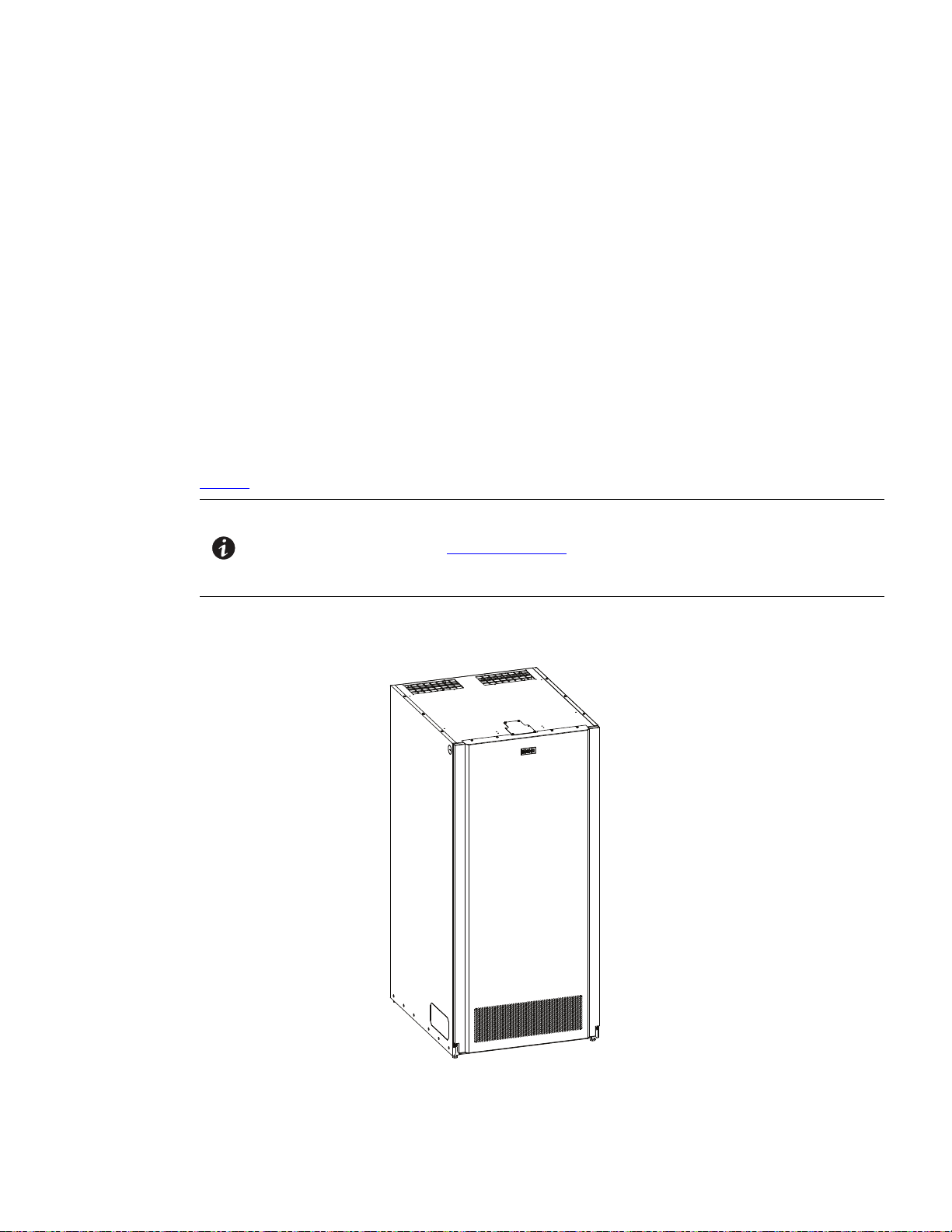
The IBC-LW and IBC-LHW are housed in a single free-standing cabinet with a safety shield behind the front
door for hazardous voltage protection. UPS systems 200 kW and below can utilize up to four IBC-LWs per UPS
or two IBC-LHWs per UPS to meet application runtime needs. 400 kW UPS systems can utilize up to eight IBCLWs per UPS or four IBC-LHWs per UPS to meet application runtime needs. The cabinets match the UPS
cabinet in style and color.
The IBCs are equipped with valve-regulated lead-acid (VRLA) batteries. Removable battery trays with quick
disconnects between trays reduce battery maintenance time. A DC-rated circuit breaker within each cabinet
provides protection and servicing isolation. The IBC-LHW is available with battery voltage of 432 or 480 Vdc.
Figure 1 shows the Eaton 93PM IBC-LW or Eaton 93PM IBC-LHW.
NOTE Startup and operational checks must be performed by an authorized Eaton Customer
Service Engineer, or the warranty terms specified on the product's resources page
become void. See Chapter 8 Warranty for details. This service is offered as part of the
sales contract for the UPS. Contact an Eaton service representative in advance (a
minimum two-week notice is required) to reserve a preferred startup date.
Figure 1. Eaton 93PM IBC-LW or Eaton 93PM IBC-LHW
Eaton 93PM Universal Integrated Battery Cabinet (IBC-LW and IBC-LHW) Installation Manual P-164000541—Rev 04 1
Introduction
11..11 IInnssttaallllaattiioonn FFeeaattuurreess
• Line-up-and-match configurations using factory supplied power wiring or standalone configurations using
customer supplied power wiring.
• Battery wiring can be run internally through the left or right sides of the IBCs in line-up-and-match
configurations or routed through the top or bottom of the IBCs using conduit in standalone configurations.
• Easily accessible mechanical terminals located at the bottom front of the cabinet reduce installation time.
• Interface wiring can be routed through the top left or right sides of the IBCs in line-up-and-match
configurations or through the top or bottom of the IBCs using conduit in standalone configurations.
• IBCs can be installed in a single lineup.
• Built-in casters for easy cabinet placement.
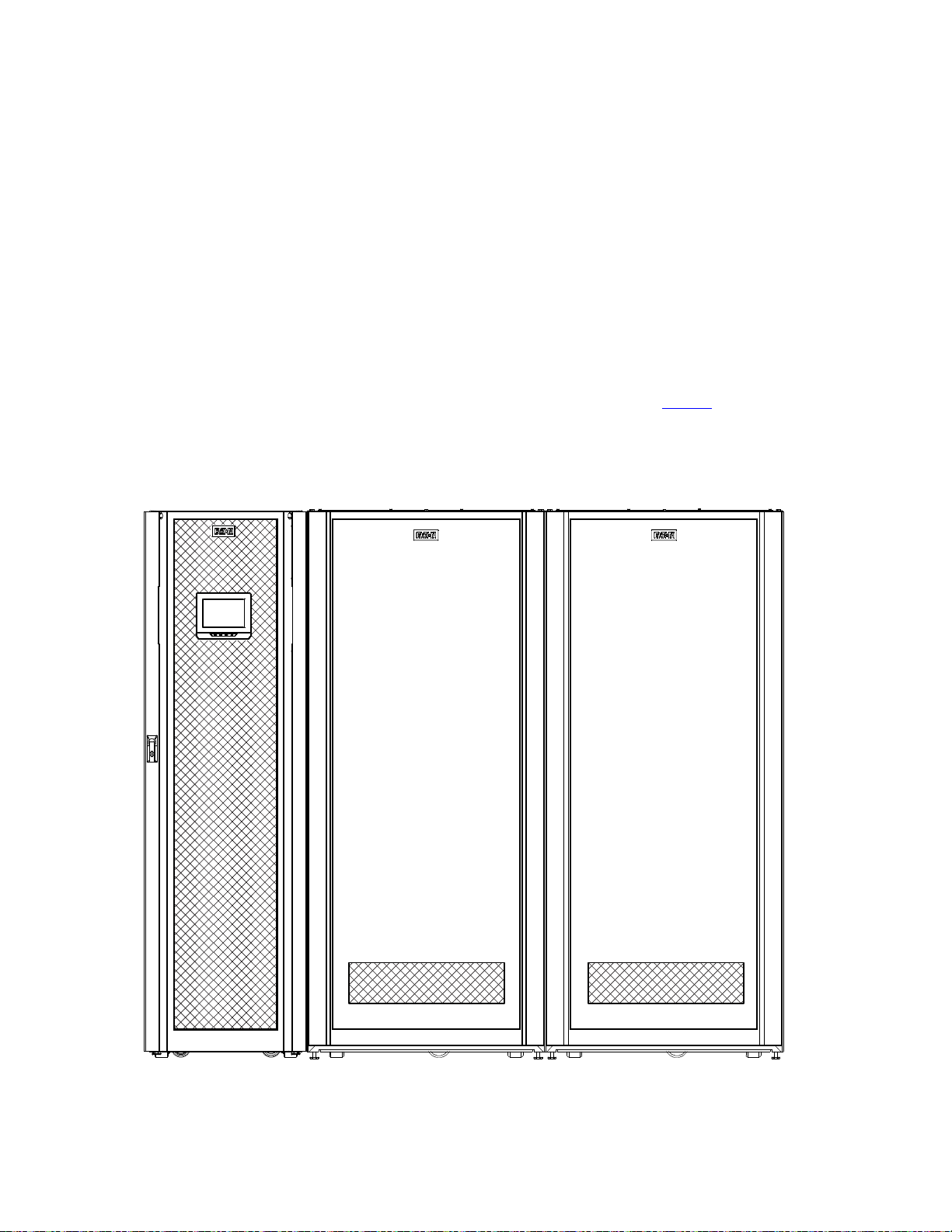
Line-up-and-match battery cabinets are installed adjacent to the UPS. The recommended installation location is
on the right side of the UPS cabinet as viewed from the front of the cabinet. See Figure 2 for line-up-and-match
configuration view.
Figure 2. Typical Eaton 93PM UPS and Two Eaton 93PM Universal Integrated Battery Cabinets
2 Eaton 93PM Universal Integrated Battery Cabinet (IBC-LW and IBC-LHW) Installation Manual P-164000541—Rev 04

11..22 OOppttiioonnaall TThheerrmmaall SSeennssoorr
Thermal runaway protection for VRLA batteries can be provided by installing an optional thermal sensor inside
the battery cabinet.
The sensor is wired to an UPS building alarm programmed to turn the charger off when a trip signal is received.
The thermal sensor will maintain the trip state until the temperature it is reset by service. Service should be
called to inspect the batteries and reset the sensor in case of such an event.
11..33 MMooddeell CCoonnffiigguurraattiioonnss
The following model configurations are available:
• Eaton 93PM Universal Integrated Battery Cabinet-Large (432V and 480V)
– Line-up-and-match, top or bottom entry standalone.
– Contains one battery string to be used with Eaton 93PM UPS systems.
– Available B37, E28, E39, E54, N54, or H41 batteries.
– Up to four IBC-LWs can be paralleled to extend the run time. Use with a Eaton 93PM-L 20-120 kW
(208V) UPS. Use with a Eaton 93PM 20-50 kW UPS, Eaton 93PM 20-100 kW UPS, Eaton 93PM 20150 kW UPS, or Eaton 93PM 20-200 kW UPS.
– Up to eight IBC-LWs can be paralleled to extend the run time. Use with a Eaton 93PM 100-400 kW
UPS.
• Eaton 93PM Universal Integrated Battery Cabinet-Large High Rate (432V and 480V)
Introduction
– Line-up-and-match, top or bottom entry standalone.
– Contains one battery string to be used with Eaton 93PM UPS systems.
– Available B37, E54, N54 or H41 batteries.
– Up to two IBC-LHWs can be paralleled to extend the run time. Use with a Eaton 93PM-L 20-120 kW
(208V) UPS. Use with a Eaton 93PM 20-50 kW UPS, Eaton 93PM 20-100 kW UPS, Eaton 93PM 20150 kW UPS, or Eaton 93PM 20-200 kW UPS.
– Up to four IBC-LHWs can be paralleled to extend the run time. Use with a Eaton 93PM 100-400 kW
UPS.
NOTE The Eaton IBC-LW or IBC-LHW 480 Vdc version is required when using the 480V Four
11..44 UUssiinngg TThhiiss MMaannuuaall
This manual describes how to install the IBC and is divided into chapters. Read and understand the procedures
described to ensure trouble-free installation and operation.
Read through each procedure before beginning the procedure. Perform only those procedures that apply to the
UPS system being installed or operated.
Wire 93PM UPS systems.
Eaton 93PM Universal Integrated Battery Cabinet (IBC-LW and IBC-LHW) Installation Manual P-164000541—Rev 04 3

RISK OF ELECTRIC SHOCK - Observe the warning associated with the risk of
electric shock symbol.
RISK OF ELECTRIC SHOCK - Observe the warning associated with the risk of
electric shock symbol.
CAUTION: REFER TO OPERATOR'S MANUAL - Refer to your operator's manual for
additional information, such as important operating and maintenance
instructions.
RISK OF ELECTRIC SHOCK - Observe the warning associated with the risk of
electric shock symbol.
CAUTION: REFER TO OPERATOR'S MANUAL - Refer to your operator's manual for
additional information, such as important operating and maintenance
instructions.
This symbol indicates that you should not discard the UPS or the UPS batteries
in the trash. This product contains sealed, lead‐acid batteries and must be
disposed of properly. For more information, contact your local recycling/reuse or
hazardous waste center.
This symbol indicates that you should not discard waste electrical or electronic
equipment (WEEE) in the trash. For proper disposal, contact your local
recycling/reuse or hazardous waste center.
Introduction
11..55 CCoonnvveennttiioonnss UUsseedd iinn TThhiiss MMaannuuaall
This manual uses these type conventions:
• Bold type highlights important concepts in discussions, key terms in procedures, and menu options, or
represents a command or option that you type or enter at a prompt.
• Italic type highlights notes and new terms where they are defined.
• Screen type represents information that appears on the screen or LCD.
Icon
Note Information notes call attention to important features or instructions.
[Keys] Brackets are used when referring to a specific key, such as [Enter] or [Ctrl].
In this manual, the term UPS refers only to the UPS cabinet and its internal elements. The term UPS system
refers to the entire power protection system – the UPS cabinet, an external battery system, and options or
accessories installed.
The term line-up-and-match refers to accessory cabinets that are physically located adjacent to the UPS. The
term standalone refers to accessory cabinets that are located separate from the UPS.
Left and right side notations are referenced standing in front of the cabinet.
Description
11..66 SSyymmbboollss,, CCoonnttrroollss,, aanndd IInnddiiccaattoorrss
The following are examples of symbols used on the UPS or accessories to alert you to important information:
RISK OF ELECTRIC SHOCK - Observe the warning associated with the risk of electric shock symbol.
CAUTION: REFER TO OPERATOR'S MANUAL - Refer to your operator's manual for additional
information, such as important operating and maintenance instructions.
This symbol indicates that you should not discard the UPS or the UPS batteries in the trash. This
product contains sealed, lead-acid batteries and must be disposed of properly. For more information,
contact your local recycling/reuse or hazardous waste center.
This symbol indicates that you should not discard waste electrical or electronic equipment (WEEE) in
the trash. For proper disposal, contact your local recycling/reuse or hazardous waste center.
4 Eaton 93PM Universal Integrated Battery Cabinet (IBC-LW and IBC-LHW) Installation Manual P-164000541—Rev 04

11..77 FFoorr MMoorree IInnffoorrmmaattiioonn
Refer to the following manuals for the information listed below:
• Eaton 93PM–L UPS (20–60 kW, 208V) Installation and Operation Manual
• Eaton 93PM–L UPS (20–120 kW, 208V) Installation and Operation Manual
• Eaton 93PM–L UPS (20–160 kW, 208V) Installation and Operation Manual
• Eaton 93PM–L UPS (20–200 kW, 208V) Installation and Operation Manual
• Eaton 93PM UPS 480V Three-Wire – 50 kW Frame Installation and Operation Manual
• Eaton 93PM UPS 400V/480V Four-Wire – 50 kW Frame Installation and Operation Manual
• Eaton 93PM UPS 480V Three-Wire – 100 kW Frame Installation and Operation Manual
• Eaton 93PM UPS 400V/480V Four-Wire –100 kW Frame Installation and Operation Manual
• Eaton 93PM UPS 480V Three-Wire 150 kW Frame Installation and Operation Manual
• Eaton 93PM UPS 400V/480V Four-Wire – 150 kW Frame Installation and Operation Manual
• Eaton 93PM UPS 480V Three-Wire – 200 kW Frame Installation and Operation Manual
• Eaton 93PM UPS 400V/480V Four-Wire – 200 kW Frame Installation and Operation Manual
• Eaton 93PM UPS 480V Three-Wire – 400 kW Frame Installation and Operation Manual
Introduction
1. UPS, optional components, and accessory installation instructions, including site preparation, planning for
installation, and wiring and safety information. Detailed illustrations of cabinets and optional accessories
with dimensional and connection point drawings are provided.
2. UPS operation, including UPS controls, functions of the UPS, standard features and optional accessories,
procedures for starting and stopping the UPS, and information about maintenance and responding to
system events.
3. Communication capabilities of the UPS system.
Visit www.eaton.com/powerquality or contact an Eaton service representative for information on how to obtain
copies of these manuals.
11..88 GGeettttiinngg HHeellpp
If help is needed with any of the following:
• Scheduling initial startup
• Regional locations and telephone numbers
• A question about any of the information in this manual
• A question this manual does not answer
Please call the Customer Reliability Center at:
United States:
Canada:
All other countries: Call your local service representative
1-800-843-9433
1-800-461-9166 ext 260
Please use the following e-mail address for manual comments, suggestions, or to report an error in this
manual: E-ESSDocumentation@eaton.com
Eaton 93PM Universal Integrated Battery Cabinet (IBC-LW and IBC-LHW) Installation Manual P-164000541—Rev 04 5

Introduction
11..99 EEqquuiippmmeenntt RReeggiissttrraattiioonn
Please visit www.eaton.com/pq/register to register your new Eaton UPS / Eaton UPS Accessory.
Model Number:
Serial Number:
6 Eaton 93PM Universal Integrated Battery Cabinet (IBC-LW and IBC-LHW) Installation Manual P-164000541—Rev 04

CChhaapptteerr 22 SSaaffeettyy WWaarrnniinnggss
IMPORTANT SAFETY INSTRUCTIONS SAVE THESE INSTRUCTIONS
This manual contains important instructions that should be followed during installation and maintenance of the
UPS system and batteries. Read all instructions before operating the equipment and save this manual for future
reference.
The UPS system is designed for industrial or computer room applications, and contains safety shields behind
the door and front panels. However, the UPS system is a sophisticated power system and should be handled
with appropriate care.
This UPS system contains LETHAL VOLTAGES. All repairs and service should be performed by AUTHORIZED
SERVICE PERSONNEL ONLY. There are NO USER SERVICEABLE PARTS inside the UPS.
• The UPS system is powered by its own energy source (batteries). The output terminals may carry live
voltage even when the UPS is disconnected from an AC source.
• The battery cabinet contains its own energy source. The internal wiring and output terminals may carry live
voltage even when the UPS is not connected to an AC source.
• To reduce the risk of fire or electric shock, install this UPS system in a temperature and humidity
controlled, indoor environment, free of conductive contaminants. Ambient temperature must not exceed
40°C (104°F). Do not operate near water or excessive humidity (95% maximum). The system is not
intended for outdoor use.
• As a result of the connected loads high leakage current is possible. Connection to earth ground is required
for safety and proper product operation. Do not check UPS system operation by any action that includes
removal of the earth (ground) connection with loads attached.
• Ensure all power is disconnected before performing installation or service.
• Batteries can present a risk of electrical shock or burn from high short-circuit current. The following
precautions should be observed: 1) Remove watches, rings, or other metal objects; 2) Use tools with
insulated handles; 3) Do not lay tools or metal parts on top of batteries; 4) Wear voltage rated gloves and
electrical hazard footwear.
• ELECTRIC ENERGY HAZARD. Do not attempt to alter any UPS system or battery wiring or connectors.
Attempting to alter wiring can cause injury.
• Do not open or mutilate batteries. Released electrolyte is harmful to the skin and eyes. It may be toxic.
DANGER
WARNING
Eaton 93PM Universal Integrated Battery Cabinet (IBC-LW and IBC-LHW) Installation Manual P-164000541—Rev 04 7

Safety Warnings
• Installation or servicing should be performed by qualified service personnel knowledgeable of UPS and
• Batteries may only be replaced with the same number and type by authorized service personnel. No user
• The UPS system has been evaluated for use with a maximum of four 93PM EBCs. Use of any other
• Disconnect the charging source prior to connecting or disconnecting battery terminals.
• Determine if the battery is inadvertently grounded. If it is, remove the source of the ground. Contacting any
• Proper disposal of batteries is required. Refer to local codes for disposal requirements.
• Do not dispose of batteries in a fire. Batteries may explode when exposed to flame.
• Keep the Accessory cabinet doors closed and front panels installed to ensure proper cooling airflow and to
• Do not install or operate the UPS system close to gas or electric heat sources.
• Lead-acid batteries can present a risk of fire because they generate hydrogen gas. Do not smoke when
• The operating environment should be maintained within the parameters stated in this manual.
• Operating temperatures above the recommended range will result in decreased battery life and
• The shelf life for the batteries installed in the IBC is 12 months from the date code on the battery. The
• Keep surroundings uncluttered, clean, and free from excess moisture.
• Observe all DANGER, CAUTION, and WARNING notices affixed to the inside and outside of the
CAUTION
battery systems, and required precautions. Keep unauthorized personnel away from equipment. Consider
all warnings, cautions, and notes before installing or servicing equipment. DO NOT DISCONNECT the
batteries while the UPS is in Battery mode.
serviceable parts.
configuration may result in fire, death, and voiding of the warranty.
part of a grounded battery can cause a risk of electric shock. An electric shock is less likely if you
disconnect the grounding connection before you work on the batteries.
protect personnel from dangerous voltages inside the unit.
near batteries. Do not cause flame or spark in battery area. Discharge static electricity from body before
touching batteries by first touching a grounded metal surface.
performance, and will reduce or void the battery warranty. Refer to Terms and Conditions of Sale with
Battery Replacement Coverage and the Battery Replacement Price Book for more information. These
documents can be found at www.eaton.com/powerquality or contact your service representative for
information on how to obtain copies.
recharge date is also stated on a label inside the IBC.
Failure to recharge the batteries before the expiration of the shelf life will result in reduced discharge time,
shorter float service life, and will void the warranty.
equipment.
AVERTISSEMENT!
• Les batteries peuvent présenter un risque de décharge électrique ou de brûlure par des courts–circuits de
haute intensité. Prendre les précautions nécessaires.
• Pour le replacement, utiliser le même nombre et modéle des batteries.
8 Eaton 93PM Universal Integrated Battery Cabinet (IBC-LW and IBC-LHW) Installation Manual P-164000541—Rev 04

Safety Warnings
ATTENTION!
• Une mise au rebut réglementaire des batteries est obligatoire. Consulter les règlements en vigueur dans
votre localité.
• Ne jamais jeter les batteries au feu. L'exposition aux flammes risque de les faire exploser.
• Les accumulateurs au plomb-acide peuvent représenter un risque d’incendie, car ils génèrent de
l’hydrogène gazeux. Ne pas fumer près des accumulateurs. Ne pas produire de flamme ou d’étincelle dans
la zone de l’accumulateur. Dissiper l'électricité statique de votre corps en touchant une surface reliée à la
terre avant de toucher les accumulateurs.
Eaton 93PM Universal Integrated Battery Cabinet (IBC-LW and IBC-LHW) Installation Manual P-164000541—Rev 04 9

Safety Warnings
10 Eaton 93PM Universal Integrated Battery Cabinet (IBC-LW and IBC-LHW) Installation Manual P-164000541—Rev 04

CChhaapptteerr 33 IInnssttaallllaattiioonn PPllaann aanndd UUnnppaacckkiinngg
Use the following basic sequence of steps to install the Eaton 93PM Universal Integrated Battery CabinetLarge (IBC-LW) or Universal Integrated Battery Cabinet-Large High Rate (IBC-LHW):
1. Create an installation plan for the IBC.
2. Prepare your site for the IBC.
3. Inspect and unpack the IBC.
4. Unload and install the IBC, and wire the system.
5. Complete the Installation Checklist.
6. Have authorized service personnel perform preliminary operational checks and start up the system.
NOTE Startup and operational checks must be performed by an authorized Eaton Customer
Service Engineer, or the warranty terms specified on the product's resources page
become void. See Chapter 8 Warranty for details. This service is offered as part of the
sales contract for the UPS. Contact an Eaton service representative in advance (a
minimum two-week notice is required) to reserve a preferred startup date.
33..11 CCrreeaattiinngg aann IInnssttaallllaattiioonn PPllaann
Before installing the IBC, read and understand how this manual applies to the system being installed. Use the
procedures and illustrations in this section to create a logical plan for installing the IBC. This section contains
the following information:
• Physical features and requirements, including dimensions
• Power wiring installation notes
• Location of conduit and wire entry landing plates
• Location of power terminals
33..22 PPrreeppaarriinngg tthhee SSiittee
For the UPS system to operate at peak efficiency, the installation site should meet the environmental
parameters outlined in this manual. The operating environment must meet the weight, clearance, and
environmental requirements specified.
33..22..11 EEnnvviirroonnmmeennttaall aanndd IInnssttaallllaattiioonn CCoonnssiiddeerraattiioonnss
The UPS system installation, including the IBC, must meet the following guidelines:
• The system must be installed on a level floor suitable for computer or electronic equipment.
• The system must be operated at an altitude no higher than 1500m (5000 ft) without derating. For additional
information and assistance with high altitude operation, contact an Eaton service representative (see
paragraph 1.8 Getting Help).
• The system must be installed in a temperature and humidity controlled indoor area free of conductive
contaminants.
• Specifications are subject to change.
Failure to follow guidelines may void your warranty.
The basic environmental requirements for operation of the IBC are:
• The battery cabinet is rated for operation in up to a 40°C (104°F) ambient temperature.
Eaton 93PM Universal Integrated Battery Cabinet (IBC-LW and IBC-LHW) Installation Manual P-164000541—Rev 04 11

Installation Plan and Unpacking
NOTE Emergency lighting and power equipment battery cabinets (UL924) are rated for
• The batteries are rated for a 25°C (77°F) ambient temperature to extend their useful life.
• Maximum Relative Humidity: 5–95%, noncondensing
It is recommended for optimal battery life and discharge performance to keep the ambient air temperature the
battery is used in at 25°C (77°F). Operating temperatures above the recommended range will result in
decreased battery life and performance, and will reduce or void the battery warranty. Refer to Eaton's Terms
and Conditions of Sale with Battery Replacement Coverage and the Battery Replacement Price Book for more
information. These documents can be found at www.eaton.com/powerquality or contact your service
representative for information on how to obtain copies.
The IBC operating environment must meet the weight requirements shown in Table 1, Table 2, Table 3 or
Table 4 and the size requirements shown in Figure 3 through Figure 6. Dimensions are in millimeters (inches).
Specifications are subject to change.
Table 1. Eaton 93PM IBC-LW (432V) Cabinet Weights
operation in a 20°–30°C (68°–86°F) temperature environment.
CAUTION
Model
Eaton 93PM Universal Integrated Battery
Cabinet-Large with E28 Batteries
Eaton 93PM Universal Integrated Battery
Cabinet-Large with E39 Batteries
Eaton 93PM Universal Integrated Battery
Cabinet-Large with E54 Batteries
Eaton 93PM Universal Integrated Battery
Cabinet-Large with B37 Batteries
Eaton 93PM Universal Integrated Battery
Cabinet-Large with H41Batteries
Eaton 93PM Universal Integrated Battery
Cabinet-Large with N54 Batteries
Weight kg (lb)
Shipping
1430 (3154) 1385 (3054) 6 at 231 (509)
1732 (3820) 1687 (3720) 6 at 281 (620)
2034 (4486) 1989 (4386) 6 at 332 (731)
1762 (3885) 1717 (3785) 6 at 286 (631)
1719 (3791) 1674 (3691) 6 at 279 (615)
2055 (4531) 2010 (4431) 6 at 335 (739)
Installed
Point Loading
12 Eaton 93PM Universal Integrated Battery Cabinet (IBC-LW and IBC-LHW) Installation Manual P-164000541—Rev 04

Table 2. Eaton 93PM IBC-LHW (432V) Cabinet Weights
Installation Plan and Unpacking
Weight kg (lb)
Model
Universal Integrated Battery Cabinet-Large High
Rate with B37 Batteries
Universal Integrated Battery Cabinet-Large High
Rate with E54 Batteries
Universal Integrated Battery Cabinet-Large High
Rate with H41 Batteries
Universal Integrated Battery Cabinet-Large High
Rate with N54 Batteries
Table 3. Eaton 93PM IBC-LW (480V) Cabinet Weights
Model
Eaton 93PM Universal Integrated Battery
Cabinet-Large with E54 Batteries
Eaton 93PM Universal Integrated Battery
Cabinet-Large with E39 Batteries
Eaton 93PM Universal Integrated Battery
Cabinet-Large with E28 Batteries
Eaton 93PM Universal Integrated Battery
Cabinet-Large with B37 Batteries
Shipping
1795 (3957) 1750 (3857) 6 at 292 (643)
2067 (4558) 2022 (4458) 6 at 337 (743)
1752 (3863) 1707 (3763) 6 at 285 (627)
2088 (4605) 2043 (4505) 6 at 341 (751)
Shipping
2224 (4903) 2179 (4803) 6 at 363 (801)
1881 (4148) 1836 (4048) 6 at 306 (675)
1545 (3408) 1500 (3308) 6 at 250 (551)
1921 (4236) 1876 (4136) 6 at 313 (689)
Installed
Weight kg (lb)
Installed
Point Loading
Point Loading
Eaton 93PM Universal Integrated Battery
Cabinet-Large with H41 Batteries
Eaton 93PM Universal Integrated Battery
Cabinet-Large with N54 Batteries
Table 4. Eaton 93PM IBC-LHW (480V) Cabinet Weights
Model
Universal Integrated Battery Cabinet-Large High
Rate with N54 Batteries
Universal Integrated Battery Cabinet-Large High
Rate with H41 Batteries
Universal Integrated Battery Cabinet-Large High
Rate with E54 Batteries
Universal Integrated Battery Cabinet-Large High
Rate with B37 Batteries
1874 (4132) 1829 (4032) 6 at 305 (672)
2247 (4955) 2202 (4855) 6 at 367 (809)
2273 (5013) 2228 (4913) 6 at 371(819)
1900 (4189) 1855 (4089) 6 at 309 (682)
2250 (4961) 2205 (4861) 6 at 368 (810)
1947 (4293) 1902 (4193) 6 at 317 (699)
Shipping
Weight kg (lb)
Installed
Point Loading
Eaton 93PM Universal Integrated Battery Cabinet (IBC-LW and IBC-LHW) Installation Manual P-164000541—Rev 04 13
Installation Plan and Unpacking
The IBCs use natural convection cooling to regulate internal component temperature. Air inlets are in the front
of the cabinet and outlets are on the back or top of the cabinet. Allow clearance in front of, and on back or top
of the cabinet for proper air circulation. The clearances required around the IBC cabinet are shown in Table 5.
Table 5. Eaton 93PM IBC-LW and Eaton 93PM IBC-LHW Cabinet Clearances
From Top of Cabinet with Rear Exhaust Option 304.8 mm (12") working space
From Top of Cabinet with Top Exhaust Option 304.8 mm (12") minimum clearance for ventilation
From Front of Cabinet
From Back of Cabinet with Top Exhaust Option None Required
From Back of Cabinet with Rear Exhaust Option 254 mm (10") minimum clearance for ventilation
From Back of Cabinet – Seismic Installation
From Right Side of Cabinet None Required
From Left Side of Cabinet
914.4 mm (36") working space
914.4 mm (36") working space
None Required
CAUTION
The shelf life for the batteries installed in the IBC are 6 months from the date code on the battery for the B37
batteries, 8 months from the date code on the battery for the E28, E39 and E54 batteries and 24 months from
the date code on the battery for the N54 and H41 batteries. The recharge date is also stated on a label inside
the IBC.
Failure to recharge the batteries before the expiration of the shelf life will result in reduced discharge time,
shorter float service life, and will void the warranty.
14 Eaton 93PM Universal Integrated Battery Cabinet (IBC-LW and IBC-LHW) Installation Manual P-164000541—Rev 04
 Loading...