

Eaton IBC-L, IBC-LH, 93PM IBC-L, 93PM IBC-LH Installation Manuals

Eaton® 93PM Integrated Battery Cabinet-Large and Large High Rate
IBC-L
IBC-LH (432V)
IBC-LH (480V)
Installation Manual
p/n: 164000228
Revision 08

IMPORTANT SAFETY INSTRUCTIONS SAVE THESE INSTRUCTIONS
!
This manual contains important instructions that should be followed during installation and
maintenance of the UPS and batteries. Read all instructions before operating the equipment and save
this manual for future reference.
CONSIGNES DE SÉCURITÉ IMPORTANTES — CONSERVER CES INSTRUCTIONS
Ce manuel comporte des instructions importantes que vous êtes invité à suivre lors de toute
procédure d'installation et de maintenance des batteries et de l'onduleur. Veuillez consulter
entièrement ces instructions avant de faire fonctionner l'équipement et conserver ce manuel afin de
pouvoir vous y reporter ultérieurement.
IMPORTANT
To ensure you have the most up-to-date content and information for this product, please review the
latest manual revision on our website, www.eaton.com/93PM.
Eaton reserves the right to change specifications without prior notice. Modbus is a registered trademark of Schneider Automation, Inc.
MOXA is a registered trademark and MGate is a trademark of MOXA, Inc. Spiralock is a registered trademark of Spiralock Corporation.
KIRK is a registered trademark of Kirk Key Interlock company, LLC, a subsidiary of Halma plc. National Electrical Code and NEC are
registered trademarks of National Fire Protection Association, Inc. ERIFLEX and FLEXIBAR are registered trademark of Erico International
Corporation. All other trademarks are property of their respective companies.
©Copyright 2013-2018 Eaton, Raleigh, NC, USA. All rights reserved. No part of this document may be reproduced in any way without the
express written approval of Eaton.

TTaabbllee ooff CCoonntteennttss
11 IInnttrroodduuccttiioonn.................................................................................................................................................................................................................................................................................................... 11
1.1 Installation Features............ ..... ..... ........ ..... ..... ........ ..... ..... ........ ..... ..... ........ ..... ..... ........ ..... ..... ........ ..... ..... ..2
1.2 Optional Thermal Sensor ... ........ ..... ..... ............. ..... ............. ..... ............. ..... ..... ........ ..... ..... ........ ..... ..... ........ ..3
1.3 Model Configurations ...... ..... ..... ........ ..... ..... ........ ..... ..... ............. ..... ............. ..... ............. ..... ............. ..... ...... 3
1.4 Using This Manual ...... ........ ..... ..... ........ ..... ..... ........ ..... ..... ........ ..... ..... ............. ..... ............. ..... ............. ..... ..5
1.5 Conventions Used in This Manual ...... ..... ........ ..... ..... ........ ..... ..... ........ ..... ..... ........ ..... ..... ........ ..... ..... ........ ..... 5
1.6 Symbols, Controls, and Indicators ...... ..... ........ ..... ..... ........ ..... ..... ........ ..... ..... ........ ..... ..... ........ ..... ..... ........ ..... 5
1.7 For More Information ..... ............. ..... ............. ..... ............. ..... ..... ........ ..... ..... ........ ..... ..... ............. ..... ............ 6
1.8 Getting Help....... ..... ............. ..... ............. ..... ............. ..... ..... ........ ..... ..... ........ ..... ..... ........ ..... ..... ............. .... 7
1.9 Equipment Registration ...... ........ ..... ..... ........ ..... ..... ........ ..... ..... ........ ..... ..... ........ ..... ..... ........ ..... ..... ........ ..... 7
22 SSaaffeettyy WWaarrnniinnggss........................................................................................................................................................................................................................................................................................99
33 IInnssttaallllaattiioonn PPllaann aanndd UUnnppaacckkiinngg ...................................................................................................................................................................................................................................... 1133
3.1 Creating an Installation Plan ..... ..... ............. ..... ............. ..... ..... ........ ..... ..... ........ ..... ..... ........ ..... ..... ........ ..... .. 13
3.2 Preparing the Site ..... ..... ............. ..... ............. ..... ............. ..... ..... ........ ..... ..... ........ ..... ..... ............. ..... .......... 13
3.2.1 Environmental and Installation Considerations ..... ............. ..... ............. ..... ..... ........ ..... ..... ........ ..... ..... ........ 13
3.2.2 IBC Power Wiring Preparation .............. ..... ............. ..... ..... ........ ..... ..... ........ ..... ..... ........ ..... ..... ........ ..... .. 23
3.2.3 IBC Interface Wiring Preparation ..... ............. ..... ............. ..... ............. ..... ..... ........ ..... ..... ........ ..... ..... ........ 27
3.3 Inspecting and Unpacking the IBC.... ..... ............. ..... ............. ..... ............. ..... ..... ........ ..... ..... ........ ..... ..... ........ 28
3.4 Battery Breaker Location ... ........ ..... ..... ............. ..... ............. ..... ............. ..... ..... ........ ..... ..... ........ ..... ..... ........ 31
44 IInnssttaallllaattiioonn .................................................................................................................................................................................................................................................................................................. 3333
4.1 Preliminary Installation Information.... ........ ..... ..... ........ ..... ..... ........ ..... ..... ............. ..... ............. ..... ............. .... 33
4.2 Unloading the IBC Cabinet from the Pallet..... ..... ............. ..... ..... ........ ..... ..... ........ ..... ..... ........ ..... ..... ........ ..... .. 33
4.3 Installing IBC Power Wiring ..... ........ ..... ..... ........ ..... ..... ........ ..... ..... ........ ..... ..... ........ ..... ..... ............. ..... ....... 39
4.3.1 Line-Up-and-Match Power Wiring............ ..... ..... ........ ..... ..... ........ ..... ..... ............. ..... ............. ..... ............. 39
4.3.2 Standalone Power Wiring ...... ........ ..... ..... ........ ..... ..... ........ ..... ..... ........ ..... ..... ........ ..... ..... ........ ..... ..... ... 46
4.4 Battery Breaker Instantaneous Trip Setting ...... ..... ........ ..... ..... ........ ..... ..... ............. ..... ............. ..... ............. .... 48
4.5 Installing IBC Interface Wiring ...... ........ ..... ..... ........ ..... ..... ........ ..... ..... ........ ..... ..... ........ ..... ..... ........ ..... ..... ... 49
4.5.1 Installing Battery Detect Interface Connections.... ............. ..... ............. ..... ............. ..... ............. ..... ............. 49
4.5.2 Installing Battery Shunt Trip Interface Connections ..... ..... ..... ........ ..... ..... ........ ..... ..... ........ ..... ..... ........ ..... .. 57
4.5.3 Installing Thermal Sensor Interface Connections ...... ..... ........ ..... ..... ........ ..... ..... ........ ..... ..... ........ ..... ..... .... 59
4.6 Initial Startup .......... ..... ..... ........ ..... ..... ........ ..... ..... ........ ..... ..... ........ ..... ..... ........ ..... ..... ........ ..... ..... ........ ... 60
4.7 Completing the Installation Checklist ...... ..... ........ ..... ..... ........ ..... ..... ........ ..... ..... ........ ..... ..... ........ ..... ..... ....... 60
4.8 Installation Checklist .............. ..... ............. ..... ............. ..... ..... ........ ..... ..... ........ ..... ..... ........ ..... ..... ........ ..... .. 61
55 OOnneelliinneess aanndd SScchheemmaattiiccss.......................................................................................................................................................................................................................................................... 6633
5.1 Power Onelines .............. ..... ..... ........ ..... ..... ........ ..... ..... ........ ..... ..... ........ ..... ..... ........ ..... ..... ........ ..... ..... ... 63
5.2 Interface Onelines ............... ..... ............. ..... ..... ........ ..... ..... ........ ..... ..... ............. ..... ............. ..... ............. .... 67
5.3 Schematics ..... ........ ..... ..... ........ ..... ..... ........ ..... ..... ........ ..... ..... ........ ..... ..... ........ ..... ..... ............. ..... .......... 68
Eaton 93PM Integrated Battery Cabinet (IBC-L, IBC-LH [432V], and IBC-LH [480V]) Installation Manual 164000228—Rev 08 iii

Table of Contents
66 MMaaiinntteennaannccee.............................................................................................................................................................................................................................................................................................. 7711
6.1 Important Safety Instructions ..... ..... ........ ..... ..... ........ ..... ..... ........ ..... ..... ........ ..... ..... ........ ..... ..... ........ ..... ..... 71
6.2 Performing Preventive Maintenance ... ..... ........ ..... ..... ........ ..... ..... ........ ..... ..... ........ ..... ..... ........ ..... ..... ........ ... 71
6.2.1 DAILY Maintenance .......... ..... ..... ........ ..... ..... ........ ..... ..... ........ ..... ..... ........ ..... ..... ........ ..... ..... ........ ..... . 71
6.2.2 PERIODIC Maintenance.. ..... ..... ........ ..... ..... ........ ..... ..... ........ ..... ..... ............. ..... ............. ..... ............. .... 71
6.2.3 ANNUAL Maintenance.... ..... ..... ........ ..... ..... ........ ..... ..... ........ ..... ..... ............. ..... ............. ..... ............. .... 71
6.2.4 BATTERY Maintenance... ..... ..... ........ ..... ..... ........ ..... ..... ........ ..... ..... ............. ..... ............. ..... ............. .... 71
6.2.5 BATTERY Shelf Life........ ..... ..... ........ ..... ..... ........ ..... ..... ........ ..... ..... ............. ..... ............. ..... ............. .... 72
6.3 Recycling the Used Batteries ...... ..... ........ ..... ..... ........ ..... ..... ........ ..... ..... ............. ..... ............. ..... ............. .... 72
6.4 Maintenance Training ...... ..... ..... ........ ..... ..... ........ ..... ..... ............. ..... ............. ..... ............. ..... ............. ..... .... 72
77 PPrroodduucctt SSppeecciiffiiccaattiioonnss ................................................................................................................................................................................................................................................................ 7733
7.1 Model Numbers ...... ..... ..... ........ ..... ..... ........ ..... ..... ........ ..... ..... ........ ..... ..... ........ ..... ..... ........ ..... ..... ........ ... 73
7.2 Specifications .......... ..... ..... ........ ..... ..... ........ ..... ..... ........ ..... ..... ........ ..... ..... ........ ..... ..... ............. ..... .......... 73
7.2.1 Battery Specifications....... ..... ............. ..... ............. ..... ..... ........ ..... ..... ........ ..... ..... ........ ..... ..... ........ ..... .. 73
7.2.2 Environmental and Safety Specifications..... ........ ..... ..... ........ ..... ..... ........ ..... ..... ........ ..... ..... ........ ..... ..... ... 74
88 WWaarrrraannttyy ........................................................................................................................................................................................................................................................................................................ 7755
8.1 Limited Factory Warranty for Three-Phase Eaton 93PM UPS and 93PM UPS Accessory Products... ..... ........ ..... ..... .... 75
iv Eaton 93PM Integrated Battery Cabinet (IBC-L, IBC-LH [432V], and IBC-LH [480V]) Installation Manual 164000228—Rev 08

LLiisstt ooff FFiigguurreess
Figure 1. Eaton 93PM IBC-L or 93PM IBC-LH ......... ..... ..... ............. ..... ............. ..... ............. ..... ..... ........ ..... ..... ... 1
Figure 2. Eaton 93PM IBC-L or 93PM IBC-LH with Left or Right Mounted Sidecar .. ..... ........ ..... ..... ........ ..... ..... ........ . 2
Figure 3. Eaton 93PM 100 kW UPS and Two 93PM Integrated Battery Cabinets ... ..... ........ ..... ..... ........ ..... ..... ........ ..3
Figure 4. IBC-L or IBC-LH Dimensions (Front and Right Side Views) ..... ..... ........ ..... ..... ........ ..... ..... ........ ..... ..... .... 17
Figure 5. IBC-L or IBC-LH Dimensions (Rear Views) ..... ..... ........ ..... ..... ........ ..... ..... ........ ..... ..... ........ ..... ..... ....... 18
Figure 6. IBC-L or IBC-LH Dimensions (Top and Bottom Views) .. ........ ..... ..... ........ ..... ..... ........ ..... ..... ........ ..... ..... 19
Figure 7. IBC-L or IBC-LH with Factory Installed Side Car Dimensions (Front and Top View).. ........ ..... ..... ........ ..... ..... 20
Figure 8. IBC-L or IBC-LH Center of Gravity ... ........ ..... ..... ........ ..... ..... ........ ..... ..... ........ ..... ..... ........ ..... ..... ....... 21
Figure 9. IBC-L or IBC-LH with Left-Mounted or Right-Mounted Sidecar Center of Gravity...... ..... ........ ..... ..... ........ ... 22
Figure 10. Eaton 93PM IBC-L or 93PM IBC-LH as Shipped on Pallet.... ..... ........ ..... ..... ........ ..... ..... ........ ..... ..... ....... 29
Figure 11. Eaton 93PM IBC-L or 93PM IBC-LH with Left or Right-Mounted Sidecar as Shipped on Pallet ... ........ ..... ..... . 30
Figure 12. Eaton 93PM IBC-L or 93PM IBC-LH (432V) Battery Breaker Location – Front View with Door
Removed ... ..... ..... ........ ..... ..... ........ ..... ..... ........ ..... ..... ........ ..... ..... ........ ..... ..... ............. ..... .......... 31
Figure 13. Eaton 93PM IBC-LH (480V) Battery Breaker Location – Front View with Door Removed ........ ..... ............. .... 32
Figure 14. Removing the Pallet Skids and Supports – Eaton 93PM IBC-L.... ............. ..... ..... ........ ..... ..... ........ ..... ..... . 35
Figure 15. Line-Up-and-Match Wiring Access Locations........ ..... ..... ........ ..... ..... ........ ..... ..... ........ ..... ..... ............. . 37
Figure 16. Rear Ventilation .... ..... ........ ..... ..... ............. ..... ............. ..... ............. ..... ............. ..... ..... ........ ..... ..... . 38
Figure 17. Top Ventilation.... ..... ..... ........ ..... ..... ........ ..... ..... ........ ..... ..... ........ ..... ..... ........ ..... ..... ........ ..... ..... ... 39
Figure 18. DC Power Terminal Locations – Eaton 93PM IBC-L (432V) ..... ..... ..... ............. ..... ............. ..... ............. .... 41
Figure 19. DC Power Terminal Detail – Eaton 93PM IBC-L (432V) ...... ............. ..... ..... ........ ..... ..... ........ ..... ..... ........ 42
Figure 20. DC Power Terminal Locations – Eaton 93PM IBC-LH (432V) ... ..... ........ ..... ..... ........ ..... ..... ........ ..... ..... .... 43
Figure 21. DC Power Terminal Detail – Eaton 93PM IBC-LH (432V) ..... ..... ............. ..... ..... ........ ..... ..... ............. ..... .. 44
Figure 22. DC Power Terminal Locations – Eaton 93PM IBC-LH (480V) ... ..... ........ ..... ..... ........ ..... ..... ........ ..... ..... .... 45
Figure 23. DC Power Terminal Detail – Eaton 93PM IBC-LH (480V) ..... ..... ............. ..... ..... ........ ..... ..... ............. ..... .. 46
Figure 24. IBC Bottom Entry Conduit and Wire Entry Locations ... ..... ........ ..... ..... ........ ..... ..... ........ ..... ..... ........ ..... . 48
Figure 25. IBC Sidecar Top Entry Conduit and Wire Entry Locations ...... ..... ........ ..... ..... ........ ..... ..... ............. ..... ..... 48
Figure 26. Battery Breaker Instantaneous Trip Setting Dials..... ........ ..... ..... ........ ..... ..... ........ ..... ..... ........ ..... ..... .... 49
Figure 27. Interface Terminal Locations – Eaton 93PM IBC-L (432V) or 93PM IBC-LH (432V) ... ............. ..... ............. .... 51
Figure 28. Interface Terminal Locations – Eaton 93PM IBC-LH (480V).... ..... ........ ..... ..... ........ ..... ..... ............. ..... ..... 52
Figure 29. Shunt Trip, Battery Detect, and Thermal Sensor Wiring ...... ..... ........ ..... ..... ........ ..... ..... ........ ..... ..... ....... 55
Figure 30. Interface Terminal Detail – Eaton 93PM IBC-L (432V) or 93PM IBC-LH (432V) ..... ..... ..... ............. ..... .......... 56
Figure 31. Interface Terminal Detail – Eaton 93PM IBC-LH (480V) ... ..... ........ ..... ..... ........ ..... ..... ........ ..... ..... ........ ... 57
Figure 32. 93PM IBC-L Line-Up-and-Match Power Oneline............. ..... ............. ..... ............. ..... ............. ..... ..... ..... 63
Figure 33. 93PM IBC-L Standalone Power Online – One or Two Cabinets..... ..... ............. ..... ............. ..... ............. .... 64
Figure 34. 93PM IBC-L Standalone Power Online – Four Cabinets ..... ..... ........ ..... ..... ........ ..... ..... ............. ..... ........ 64
Figure 35. 93PM IBC-LH Line-Up-and-Match Power Oneline ..... ............. ..... ............. ..... ............. ..... ............. ..... .. 65
Figure 36. 93PM IBC-LH Standalone Power Online – One Cabinet ..... ..... ..... ........ ..... ..... ........ ..... ..... ........ ..... ..... ... 65
Figure 37. 93PM IBC-LH Standalone Power Online – Two Cabinets ..... ..... ............. ..... ............. ..... ..... ........ ..... ..... . 66
Figure 38. 93PM Integrated Battery Cabinet Interface Oneline............ ..... ............. ..... ............. ..... ..... ........ ..... ..... . 67
Eaton 93PM Integrated Battery Cabinet (IBC-L, IBC-LH [432V], and IBC-LH [480V]) Installation Manual 164000228—Rev 08 v

List of Figures
Figure 39. 93PM Integrated Battery Cabinet Schematic – IBC-L and IBC-LH (432V) ...... ..... ........ ..... ..... ........ ..... ..... ... 69
Figure 40. 93PM Integrated Battery Cabinet Schematic – IBC-LH (480V) .......... ..... ..... ........ ..... ..... ........ ..... ..... ........ 70
vi Eaton 93PM Integrated Battery Cabinet (IBC-L, IBC-LH [432V], and IBC-LH [480V]) Installation Manual 164000228—Rev 08

LLiisstt ooff TTaabblleess
Table 1. IBC-L Cabinet Weights ........ ..... ..... ........ ..... ..... ........ ..... ..... ........ ..... ..... ........ ..... ..... ........ ..... ..... ....... 14
Table 2. IBC-LH (432V) Cabinet Weights ... ........ ..... ..... ........ ..... ..... ........ ..... ..... ........ ..... ..... ........ ..... ..... ........ ... 15
Table 3. IBC-LH (480V) Cabinet Weights ... ........ ..... ..... ........ ..... ..... ........ ..... ..... ........ ..... ..... ........ ..... ..... ........ ... 15
Table 4. IBC-L and IBC-LH Cabinet Clearances ... ........ ..... ..... ........ ..... ..... ........ ..... ..... ........ ..... ..... ........ ..... ..... ... 16
Table 5. Line-Up-and-Match External Power Wiring Recommendations – Eaton 93PM IBC-L and 93PM IBC-LH. ........ ... 24
Table 6. Standalone External Power Wiring Recommendations - Eaton 93PM IBC-L...... ..... ............. ..... ............. ..... . 25
Table 7. Standalone External Power Wiring Recommendations - Eaton 93PM IBC-LH ...... ..... ..... ........ ..... ..... ........ ... 26
Table 8. External Power Cable Terminations – Eaton 93PM IBC-L and 93PM IBC-LH ........ ..... ..... ........ ..... ..... ........ ... 27
Table 9. Recommended DC Circuit Breaker or Disconnect Ratings (Three or Four IBC-Ls or Two IBC-LHs) .. ..... ........ ... 27
Table 10. IBC TB2 or TB3 Interface Connections (432V) ... ..... ............. ..... ............. ..... ............. ..... ..... ........ ..... ..... . 53
Table 11. IBC TB2 or TB3 Interface Connections (480V) ... ..... ............. ..... ............. ..... ............. ..... ..... ........ ..... ..... . 54
Table 12. IBC TB2 or TB3 Interface Wiring Terminal Block Terminations..... ............. ..... ..... ........ ..... ..... ........ ..... ..... . 56
Eaton 93PM Integrated Battery Cabinet (IBC-L, IBC-LH [432V], and IBC-LH [480V]) Installation Manual 164000228—Rev 08 vii

List of Tables
viii Eaton 93PM Integrated Battery Cabinet (IBC-L, IBC-LH [432V], and IBC-LH [480V]) Installation Manual 164000228—Rev 08
CChhaapptteerr 11 IInnttrroodduuccttiioonn
The Eaton® 93PM Integrated Battery Cabinet-Large (IBC-L) and Integrated Battery Cabinet-Large High Rate
(IBC-LH) provide extended emergency short-time backup power for 93PM UPS systems to enhance the
usability and reliability of the systems. The IBC-L and IBC-LH safeguard operation during brownouts, blackouts,
and other power interruptions providing cost-effective extended battery run time. In addition, the IBC-LH
provides a single battery cabinet solution for 93PM UPS systems 200 kW and below. 93PM 400 kW UPS
systems above 200 kW require at least two battery cabinets.
The IBC-L and IBC-LH are housed in a single free-standing cabinet with safety shields behind the doors for
hazardous voltage protection. UPS systems 200 kW and below can utilize up to four IBC-Ls per UPS or two
IBC-LHs per UPS to meet application runtime needs. 400 kW UPS systems can utilize up to eight IBC-Ls per
UPS or four IBC-LHs per UPS to meet application runtime needs. The cabinets match the UPS cabinet in style
and color.
The IBCs are equipped with valve-regulated lead-acid (VRLA) batteries. Removable battery trays with quick
disconnects between trays reduce battery maintenance time. A DC-rated circuit breaker within each cabinet
provides protection and servicing isolation. The IBC-LH is available with battery voltage of 432 or 480 Vdc.
Figure 1 shows the IBC-L or IBC-LH, and Figure 2 shows the IBC-L or IBC-LH with a left or right mounted
sidecar.
NOTE Startup and operational checks must be performed by an authorized Eaton Customer
Service Engineer, or the warranty terms specified in Chapter 8 Warranty become void.
This service is offered as part of the sales contract for the UPS. Contact an Eaton service
representative in advance (a minimum two-week notice is required) to reserve a
preferred startup date.
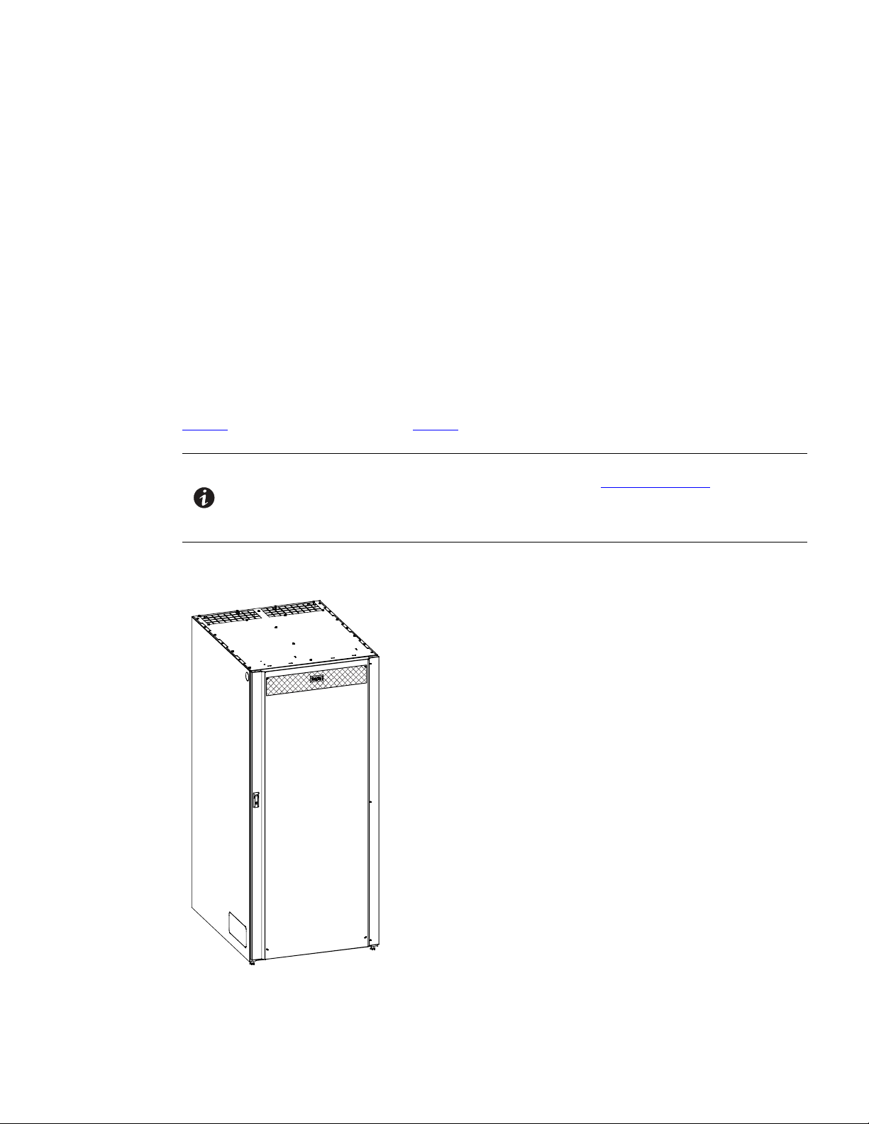
Figure 1. Eaton 93PM IBC-L or 93PM IBC-LH
Eaton 93PM Integrated Battery Cabinet (IBC-L, IBC-LH [432V], and IBC-LH [480V]) Installation Manual 164000228—Rev 08 1
Introduction
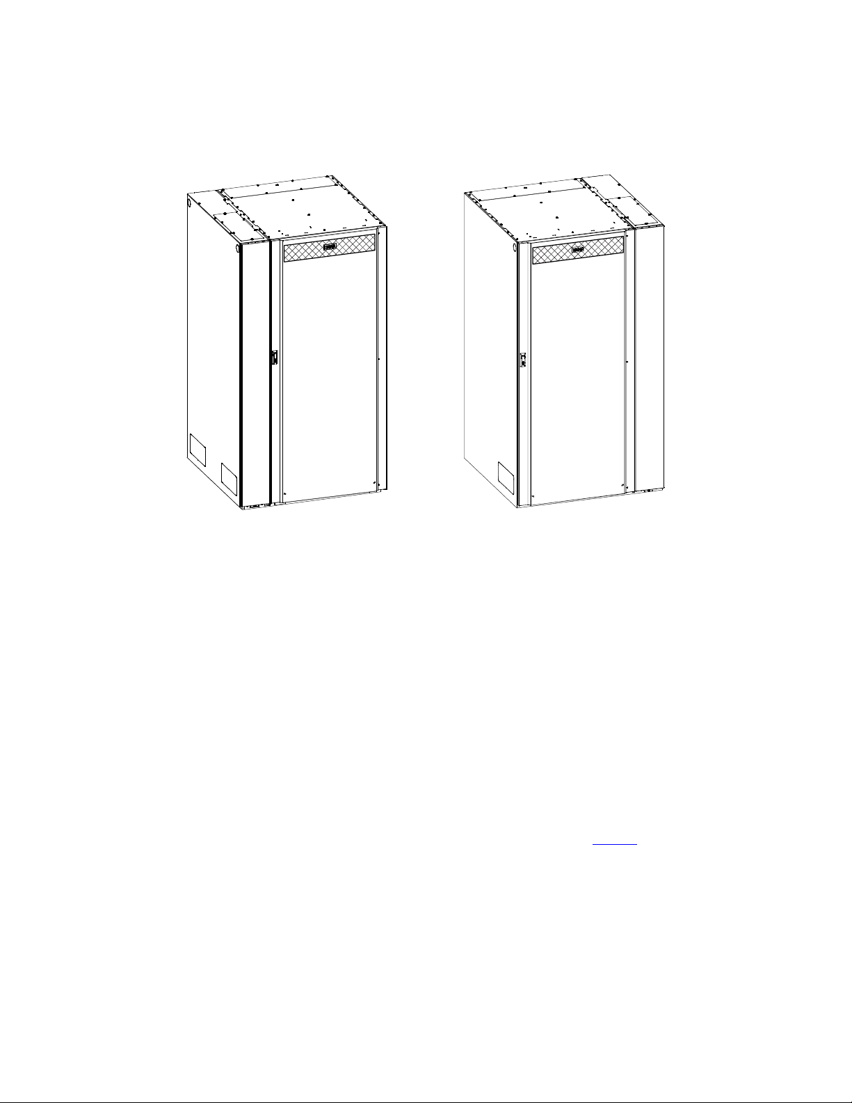
Figure 2. Eaton 93PM IBC-L or 93PM IBC-LH with Left or Right Mounted Sidecar
11..11 IInnssttaallllaattiioonn FFeeaattuurreess
• Line-up-and-match configurations using factory supplied power wiring or standalone configurations using
customer supplied power wiring
• Battery wiring can be run internally through the left or right sides of the IBCs in line-up-and-match
configurations or routed through the bottom of the IBCs using conduit in standalone configurations
• A factory installed sidecar option is available for standalone installations needing top entry wiring.
• Only one sidecar is needed for multiple IBCs.
• Easily accessible mechanical terminals located at the bottom front of the cabinet reduce installation time.
• Interface wiring can be routed through the top left or right sides of the IBCs in line-up-and-match
configurations or through the top or bottom of the IBCs using conduit in standalone configurations.
• IBCs with and without a sidecar can be installed in a single lineup.
• Built-in casters for easy cabinet placement.
Line-up-and-match battery cabinets are installed adjacent to the UPS. The recommended installation location is
on the right side of the UPS cabinet as viewed from the front of the cabinet. See Figure 3 for line-up-and-match
configuration views.
2 Eaton 93PM Integrated Battery Cabinet (IBC-L, IBC-LH [432V], and IBC-LH [480V]) Installation Manual 164000228—Rev 08
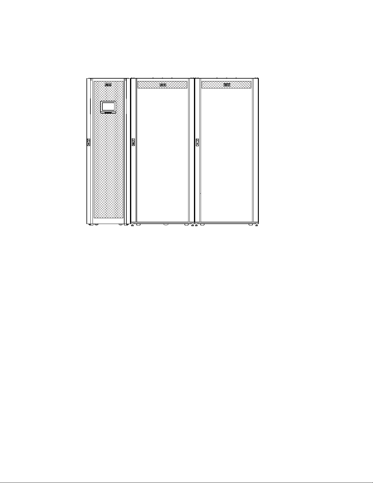
Figure 3. Eaton 93PM 100 kW UPS and Two 93PM Integrated Battery Cabinets
Introduction
11..22 OOppttiioonnaall TThheerrmmaall SSeennssoorr
Thermal runaway protection for VRLA batteries can be provided by installing an optional thermal sensor inside
the battery cabinet.
The sensor is wired to an UPS building alarm programmed to turn the charger off when a trip signal is received.
The thermal sensor will maintain the trip state until the temperature it is reset by service. Service should be
called to inspect the batteries and reset the sensor in case of such an event.
11..33 MMooddeell CCoonnffiigguurraattiioonnss
The following model configurations are available:
• 93PM Integrated Battery Cabinet-Large
– Line-up-and-match or bottom entry standalone.
– Contains one battery string to be used with 93PM UPS systems.
– Available E28, E39 or E54 batteries.
– Up to four IBC-Ls can be paralleled to extend the run time. Use with a 93PM 20-50 kW UPS, 93PM 20-
100 kW UPS, 93PM 20-150 kW UPS, or 93PM 20-200 kW UPS.
– Up to eight IBC-Ls can be paralleled to extend the run time. Use with a 93PM 100-400 kW UPS
Eaton 93PM Integrated Battery Cabinet (IBC-L, IBC-LH [432V], and IBC-LH [480V]) Installation Manual 164000228—Rev 08 3

Introduction
• 93PM Integrated Battery Cabinet-Large with factory installed sidecar
– Sidecar provided for top entry standalone.
– Contains one battery string to be used with the 93PM UPS systems.
– Available E28, E39 or E54 batteries.
– Up to four IBC-Ls can be paralleled to extend the run time using one sidecar. Use with a 93PM 20-50
kW UPS, 93PM 20-100 kW UPS, 93PM 20-150 kW UPS, or 93PM 20-200 kW UPS.
– Up to eight IBC-Ls can be paralleled to extend the run time. Use with a 93PM 100-400 kW UPS
• Eaton 93PM Integrated Battery Cabinet-Large High Rate (432V)
– Line-up-and-match or bottom entry standalone.
– Contains one battery string to be used with 93PM UPS systems.
– Available B37, E54, N54 or H41 batteries
– Up to two IBC-LHs can be paralleled to extend the run time. Use with a 93PM 20-50 kW UPS,
93PM 20-100 kW UPS, 93PM 20-150 kW UPS, or 93PM 20-200 kW UPS.
– Up to four IBC-LHs can be paralleled to extend the run time. Use with a 93PM 100-400 kW UPS.
• Eaton 93PM Integrated Battery Cabinet-Large High Rate (432V) with factory installed sidecar
– Sidecar provided for top entry standalone.
– Contains one battery string to be used with the 93PM UPS systems.
– Available B37, E54, N54 or H41 batteries.
– Up to two IBC-LHs can be paralleled to extend the run time using one sidecar. Use with a 93PM 20-50
kW UPS, 93PM 20-100 kW UPS, 93PM 20-150 kW UPS, or 93PM 20-200 kW UPS.
– Up to four IBC-LHs can be paralleled to extend the run time. Use with a 93PM 100-400 kW UPS.
• Eaton 93PM Integrated Battery Cabinet-Large High Rate (480V)
– Line-up-and-match or bottom entry standalone.
– Contains one battery string to be used with 93PM UPS systems.
– Available B37 or H41 batteries
– Up to two IBC-LHs can be paralleled to extend the run time. Use with a 93PM 20-50 kW UPS,
93PM 20-100 kW UPS, 93PM 20-150 kW UPS, or 93PM 20-200 kW UPS.
– Up to four IBC-LHs can be paralleled to extend the run time. Use with a 93PM 100-400 kW UPS.
• Eaton 93PM Integrated Battery Cabinet-Large High Rate (480V) with factory installed sidecar
– Sidecar provided for top entry standalone.
– Contains one battery string to be used with the 93PM UPS systems.
– Available B37 or H41 batteries.
– Up to two IBC-LHs can be paralleled to extend the run time using one sidecar. Use with a 93PM 20-50
kW UPS, 93PM 20-100 kW UPS, 93PM 20-150 kW UPS, or 93PM 20-200 kW UPS.
– Up to four IBC-LHs can be paralleled to extend the run time. Use with a 93PM 100-400 kW UPS.
4 Eaton 93PM Integrated Battery Cabinet (IBC-L, IBC-LH [432V], and IBC-LH [480V]) Installation Manual 164000228—Rev 08

11..44 UUssiinngg TThhiiss MMaannuuaall
RISK OF ELECTRIC SHOCK - Observe the warning associated with the risk of
electric shock symbol.
RISK OF ELECTRIC SHOCK - Observe the warning associated with the risk of
electric shock symbol.
CAUTION: REFER TO OPERATOR'S MANUAL - Refer to your operator's manual for
additional information, such as important operating and maintenance
instructions.
RISK OF ELECTRIC SHOCK - Observe the warning associated with the risk of
electric shock symbol.
CAUTION: REFER TO OPERATOR'S MANUAL - Refer to your operator's manual for
additional information, such as important operating and maintenance
instructions.
This symbol indicates that you should not discard the UPS or the UPS batteries
in the trash. This product contains sealed, lead‐acid batteries and must be
disposed of properly. For more information, contact your local recycling/reuse or
hazardous waste center.
This symbol indicates that you should not discard waste electrical or electronic
equipment (WEEE) in the trash. For proper disposal, contact your local
recycling/reuse or hazardous waste center.
This manual describes how to install the IBC and is divided into chapters. Read and understand the procedures
described to ensure trouble-free installation and operation.
Read through each procedure before beginning the procedure. Perform only those procedures that apply to the
UPS system being installed or operated.
11..55 CCoonnvveennttiioonnss UUsseedd iinn TThhiiss MMaannuuaall
This manual uses these type conventions:
• Bold type highlights important concepts in discussions, key terms in procedures, and menu options, or
represents a command or option that you type or enter at a prompt.
• Italic type highlights notes and new terms where they are defined.
• Screen type represents information that appears on the screen or LCD.
Introduction
Icon
Description
Note Information notes call attention to important features or instructions.
[Keys] Brackets are used when referring to a specific key, such as [Enter] or [Ctrl].
In this manual, the term UPS refers only to the UPS cabinet and its internal elements. The term UPS system
refers to the entire power protection system – the UPS cabinet, an external battery system, and options or
accessories installed.
The term line-up-and-match refers to accessory cabinets that are physically located adjacent to the UPS. The
term standalone refers to accessory cabinets that are located separate from the UPS.
Left and right side notations are referenced standing in front of the cabinet.
11..66 SSyymmbboollss,, CCoonnttrroollss,, aanndd IInnddiiccaattoorrss
The following are examples of symbols used on the UPS or accessories to alert you to important information:
RISK OF ELECTRIC SHOCK - Observe the warning associated with the risk of electric shock symbol.
CAUTION: REFER TO OPERATOR'S MANUAL - Refer to your operator's manual for additional
information, such as important operating and maintenance instructions.
Eaton 93PM Integrated Battery Cabinet (IBC-L, IBC-LH [432V], and IBC-LH [480V]) Installation Manual 164000228—Rev 08 5
product contains sealed, lead-acid batteries and must be disposed of properly. For more information,
contact your local recycling/reuse or hazardous waste center.
This symbol indicates that you should not discard waste electrical or electronic equipment (WEEE) in
the trash. For proper disposal, contact your local recycling/reuse or hazardous waste center.
This symbol indicates that you should not discard the UPS or the UPS batteries in the trash. This

Introduction
11..77 FFoorr MMoorree IInnffoorrmmaattiioonn
Refer to the following manuals for the listed additional information:
• Eaton 93PM UPS (20-50 kW, 480V 50 kW Frame) Installation and Operation Manual
• Eaton 93PM UPS (20-50 kW, 480V Four Wire 50 kW Frame) Installation and Operation Manual
• Eaton 93PM Emergency Lighting UPS (20-40 kW, 480V Four Wire UL 924) Installation and Operation
Manual
• Eaton 93PM UPS (20-100 kW, 480V 100 kW Frame) Installation and Operation Manual
• Eaton 93PM UPS (20-100 kW, 480V Four Wire 100 kW Frame) Installation and Operation Manual
• Eaton 93PM UPS (20-150 kW, 480V 150 kW Capacity Frame) Installation and Operation Manual
• Eaton 93PM UPS (20-150 kW, 480V Four Wire 150 kW Capacity Frame) Installation and Operation Manual
• Eaton 93PM Emergency Lighting UPS (20-120 kW, 480V Four Wire UL 924) Installation and Operation
Manual
• Eaton 93PM UPS (20-200 kW, 480V 200 kW Frame) Installation and Operation Manual
• Eaton 93PM UPS (20-200 kW, 480V Four Wire 200 kW Frame) Installation and Operation Manual
• Eaton 93PM UPS (100-400 kW, 480V 400 kW Frame) Installation and Operation Manual
– UPS, optional components, and accessory installation instructions, including site preparation, planning
for installation, and wiring and safety information. Detailed illustrations of cabinets and optional
accessories with dimensional and connection point drawings are provided.
– UPS operation, including UPS controls, functions of the UPS, standard features and optional
accessories, procedures for starting and stopping the UPS, and information about maintenance and
responding to system events.
– Communication capabilities of the UPS system.
Visit www.eaton.com/powerquality or contact an Eaton service representative for information on how to obtain
copies of these manuals.
6 Eaton 93PM Integrated Battery Cabinet (IBC-L, IBC-LH [432V], and IBC-LH [480V]) Installation Manual 164000228—Rev 08

11..88 GGeettttiinngg HHeellpp
If help is needed with any of the following:
• Scheduling initial startup
• Regional locations and telephone numbers
• A question about any of the information in this manual
• A question this manual does not answer
Please call the Customer Reliability Center at:
Introduction
United States:
Canada:
All other countries: Call your local service representative
Please use the following e-mail address for manual comments, suggestions, or to report an error in this
manual:
E-ESSDocumentation@eaton.com
11..99 EEqquuiippmmeenntt RReeggiissttrraattiioonn
Please visit www.eaton.com/pq/register to register your new Eaton UPS / Eaton UPS Accessory.
Model Number:
Serial Number:
1-800-843-9433
1-800-461-9166 ext 260
Eaton 93PM Integrated Battery Cabinet (IBC-L, IBC-LH [432V], and IBC-LH [480V]) Installation Manual 164000228—Rev 08 7

Introduction
8 Eaton 93PM Integrated Battery Cabinet (IBC-L, IBC-LH [432V], and IBC-LH [480V]) Installation Manual 164000228—Rev 08

CChhaapptteerr 22 SSaaffeettyy WWaarrnniinnggss
IMPORTANT SAFETY INSTRUCTIONS SAVE THESE INSTRUCTIONS
This manual contains important instructions that should be followed during installation and maintenance of the
UPS system and batteries. Read all instructions before operating the equipment and save this manual for future
reference.
The UPS system is designed for industrial or computer room applications, and contains safety shields behind
the door and front panels. However, the UPS system is a sophisticated power system and should be handled
with appropriate care.
This UPS system contains LETHAL VOLTAGES. All repairs and service should be performed by AUTHORIZED
SERVICE PERSONNEL ONLY. There are NO USER SERVICEABLE PARTS inside the UPS.
• The UPS system is powered by its own energy source (batteries). The output terminals may carry live
voltage even when the UPS is disconnected from an AC source.
• The battery cabinet contains its own energy source. The internal wiring and output terminals may carry live
voltage even when the UPS is not connected to an AC source.
• To reduce the risk of fire or electric shock, install this UPS system in a temperature and humidity
controlled, indoor environment, free of conductive contaminants. Ambient temperature must not exceed
40°C (104°F). Do not operate near water or excessive humidity (95% maximum). The system is not
intended for outdoor use.
• As a result of the connected loads high leakage current is possible. Connection to earth ground is required
for safety and proper product operation. Do not check UPS system operation by any action that includes
removal of the earth (ground) connection with loads attached.
• Ensure all power is disconnected before performing installation or service.
• Batteries can present a risk of electrical shock or burn from high short-circuit current. The following
precautions should be observed: 1) Remove watches, rings, or other metal objects; 2) Use tools with
insulated handles; 3) Do not lay tools or metal parts on top of batteries; 4) Wear voltage rated gloves and
electrical hazard footwear.
• ELECTRIC ENERGY HAZARD. Do not attempt to alter any UPS system or battery wiring or connectors.
Attempting to alter wiring can cause injury.
• Do not open or mutilate batteries. Released electrolyte is harmful to the skin and eyes. It may be toxic.
DANGER
WARNING
Eaton 93PM Integrated Battery Cabinet (IBC-L, IBC-LH [432V], and IBC-LH [480V]) Installation Manual 164000228—Rev 08 9

Safety Warnings
• Installation or servicing should be performed by qualified service personnel knowledgeable of UPS and
• Batteries may only be replaced with the same number and type by authorized service personnel. No user
• The UPS system has been evaluated for use with a maximum of four 93PM EBCs for an Eaton 93PM 20-
• Disconnect the charging source prior to connecting or disconnecting battery terminals.
• Determine if the battery is inadvertently grounded. If it is, remove the source of the ground. Contacting any
• Proper disposal of batteries is required. Refer to local codes for disposal requirements.
• Do not dispose of batteries in a fire. Batteries may explode when exposed to flame.
• Keep the Accessory cabinet doors closed and front panels installed to ensure proper cooling airflow and to
• Do not install or operate the UPS system close to gas or electric heat sources.
• Lead-acid batteries can present a risk of fire because they generate hydrogen gas. Do not smoke when
• The operating environment should be maintained within the parameters stated in this manual.
• Operating temperatures above the recommended range will result in decreased battery life and
• The shelf life for the batteries installed in the IBC are 8 months from the date code on the battery for the
• Keep surroundings uncluttered, clean, and free from excess moisture.
• Observe all DANGER, CAUTION, and WARNING notices affixed to the inside and outside of the
CAUTION
battery systems, and required precautions. Keep unauthorized personnel away from equipment. Consider
all warnings, cautions, and notes before installing or servicing equipment. DO NOT DISCONNECT the
batteries while the UPS is in Battery mode.
serviceable parts.
50 kW UPS, Eaton 93PM 20-100 kW UPS, Eaton 93PM 20-150 kW UPS, or Eaton 93PM 20-200 kW UPS
and a maximum of eight Eaton 93PM IBCs for an Eaton 93PM 100-400 kW UPS. Use of any other
configuration may result in fire, death, and voiding of the warranty.
part of a grounded battery can cause a risk of electric shock. An electric shock is less likely if you
disconnect the grounding connection before you work on the batteries.
protect personnel from dangerous voltages inside the unit.
near batteries. Do not cause flame or spark in battery area. Discharge static electricity from body before
touching batteries by first touching a grounded metal surface.
performance, and will reduce or void the battery warranty. Refer to Terms and Conditions of Sale with
Battery Replacement Coverage and the Battery Replacement Price Book for more information. These
documents can be found at www.eaton.com/powerquality or contact your service representative for
information on how to obtain copies.
E28, E39, E54, and B37batteries and 24 months from the date code on the battery for the N54 and
H41batteries.The recharge date is also stated on a label inside the IBC. Failure to recharge the batteries
before the expiration of the shelf life will result in reduced discharge time, shorter float service life, and will
void the warranty.
equipment.
AVERTISSEMENT!
• Les batteries peuvent présenter un risque de décharge électrique ou de brûlure par des courts–circuits de
haute intensité. Prendre les précautions nécessaires.
• Pour le replacement, utiliser le même nombre et modéle des batteries.
10 Eaton 93PM Integrated Battery Cabinet (IBC-L, IBC-LH [432V], and IBC-LH [480V]) Installation Manual 164000228—Rev 08

Safety Warnings
ATTENTION!
• Une mise au rebut réglementaire des batteries est obligatoire. Consulter les règlements en vigueur dans
votre localité.
• Ne jamais jeter les batteries au feu. L'exposition aux flammes risque de les faire exploser.
• Les accumulateurs au plomb-acide peuvent représenter un risque d’incendie, car ils génèrent de
l’hydrogène gazeux. Ne pas fumer près des accumulateurs. Ne pas produire de flamme ou d’étincelle dans
la zone de l’accumulateur. Dissiper l'électricité statique de votre corps en touchant une surface reliée à la
terre avant de toucher les accumulateurs.
Eaton 93PM Integrated Battery Cabinet (IBC-L, IBC-LH [432V], and IBC-LH [480V]) Installation Manual 164000228—Rev 08 11

Safety Warnings
12 Eaton 93PM Integrated Battery Cabinet (IBC-L, IBC-LH [432V], and IBC-LH [480V]) Installation Manual 164000228—Rev 08

CChhaapptteerr 33 IInnssttaallllaattiioonn PPllaann aanndd UUnnppaacckkiinngg
Use the following basic sequence of steps to install the Eaton 93PM Integrated Battery Cabinet-Large (IBC-L)
or Integrated Battery Cabinet-Large High Rate (IBC-LH):
1. Create an installation plan for the IBC.
2. Prepare your site for the IBC.
3. Inspect and unpack the IBC.
4. Unload and install the IBC, and wire the system.
5. Complete the Installation Checklist.
6. Have authorized service personnel perform preliminary operational checks and start up the system.
NOTE Startup and operational checks must be performed by an authorized Eaton Customer
Service Engineer, or the warranty terms specified in Chapter 8 Warranty become void.
This service is offered as part of the sales contract for the UPS. Contact an Eaton service
representative in advance (a minimum two-week notice is required) to reserve a
preferred startup date.
33..11 CCrreeaattiinngg aann IInnssttaallllaattiioonn PPllaann
Before installing the IBC, read and understand how this manual applies to the system being installed. Use the
procedures and illustrations in this section to create a logical plan for installing the IBC. This section contains
the following information:
• Physical features and requirements, including dimensions
• Power wiring installation notes
• Location of conduit and wire entry landing plates
• Location of power terminals
33..22 PPrreeppaarriinngg tthhee SSiittee
For the UPS system to operate at peak efficiency, the installation site should meet the environmental
parameters outlined in this manual. The operating environment must meet the weight, clearance, and
environmental requirements specified.
33..22..11 EEnnvviirroonnmmeennttaall aanndd IInnssttaallllaattiioonn CCoonnssiiddeerraattiioonnss
The UPS system installation, including the IBC, must meet the following guidelines:
• The system must be installed on a level floor suitable for computer or electronic equipment.
• The system must be operated at an altitude no higher than 1500m (5000 ft) without derating. For additional
information and assistance with high altitude operation, contact an Eaton service representative (see
paragraph 1.8 Getting Help).
• The system must be installed in a temperature and humidity controlled indoor area free of conductive
contaminants.
• Specifications are subject to change
Failure to follow guidelines may void your warranty.
The basic environmental requirements for operation of the IBC are:
• The battery cabinet is rated for operation in up to a 40°C (104°F) ambient temperature.
Eaton 93PM Integrated Battery Cabinet (IBC-L, IBC-LH [432V], and IBC-LH [480V]) Installation Manual 164000228—Rev 08 13

Installation Plan and Unpacking
NOTE Emergency lighting and power equipment battery cabinets (UL924) are rated for
• The batteries are rated for a 25°C (77°F) ambient temperature to extend their useful life.
• Maximum Relative Humidity: 95%, noncondensing
It is recommended for optimal battery life and discharge performance to keep the ambient air temperature the
battery is used in at 25°C (77°F). Operating temperatures above the recommended range will result in
decreased battery life and performance, and will reduce or void the battery warranty. Refer to Eaton's Terms
and Conditions of Sale with Battery Replacement Coverage and the Battery Replacement Price Book for more
information. These documents can be found at www.eaton.com/powerquality or contact your service
representative for information on how to obtain copies.
The shelf life for the batteries installed in the IBC is 12 months from the date code on the battery. The recharge
date is also stated on a label inside the IBC.
Failure to recharge the batteries before the expiration of the shelf life will result in reduced discharge time,
shorter float service life, and will void the warranty.
operation in a 20°–30°C (68°–86°F) temperature environment.
CAUTION
CAUTION
The IBC operating environment must meet the weight requirements shown in Table 1, Table 2, or Table 3 and
the size requirements shown in Figure 4 through Figure 9. Dimensions are in millimeters (inches).
Specifications are subject to change.
Table 1. IBC-L Cabinet Weights
Weight kg (lb)
Model
Eaton 93PM Integrated Battery Cabinet-Large
with E54 Batteries
Eaton 93PM Integrated Battery Cabinet-Large
with E39 Batteries
Eaton 93PM Integrated Battery Cabinet-Large
with E28 Batteries
Eaton 93PM Integrated Battery Cabinet-Large
with E54 Batteries and sidecar
Eaton 93PM Integrated Battery Cabinet-Large
with E39 Batteries and sidecar
Eaton 93PM Integrated Battery Cabinet-Large
with E28 Batteries and sidecar
Shipping
2189 (4827) 2144 (4727) 7 at 306 (675)
1761 (3883) 1716 (3783) 7 at 245 (540)
1467 (3234) 1422 (3134) 7 at 203 (448)
2231 (4919) 2186 (4819) 7 at 312 (688)
1803 (3975) 1758 (3875) 7 at 251 (554)
1508 (3326) 1463 (3226) 7 at 209 (461)
Installed
Point Loading
14 Eaton 93PM Integrated Battery Cabinet (IBC-L, IBC-LH [432V], and IBC-LH [480V]) Installation Manual 164000228—Rev 08

Table 2. IBC-LH (432V) Cabinet Weights
Installation Plan and Unpacking
Weight kg (lb)
Model
Integrated Battery Cabinet-Large High Rate with
N54 Batteries
Integrated Battery Cabinet-Large High Rate with
H41 Batteries
Integrated Battery Cabinet-Large High Rate with
E54 Batteries
Integrated Battery Cabinet-Large High Rate with
B37 Batteries
Integrated Battery Cabinet-Large High Rate with
N54 Batteries and sidecar
Integrated Battery Cabinet-Large High Rate with
H41 Batteries and sidecar
Integrated Battery Cabinet-Large High Rate with
E54 Batteries and sidecar
Integrated Battery Cabinet-Large High Rate with
B37 Batteries and sidecar
Table 3. IBC-LH (480V) Cabinet Weights
Model
Integrated Battery Cabinet-Large High Rate with
H41 Batteries
Integrated Battery Cabinet-Large High Rate with
B37 Batteries
Integrated Battery Cabinet-Large High Rate with
H41 Batteries and sidecar
Integrated Battery Cabinet-Large High Rate with
B37 Batteries and sidecar
Shipping
2154 (4749) 2109 (4649) 7 at 301 (664)
1822 (4018) 1777 (3918) 7 at 254 (560)
2175 (4796) 2130 (4696) 7 at 304 (671)
1848 (4076) 1803 (3976) 7 at 258 (568)
2195 (4841) 2150 (4741) 7 at 307 (677)
1864 (4110) 1819 (4010) 7 at 260 (573)
2217 (4888) 2172 (4788) 7 at 310 (684)
1890 (4168) 1845 (4068) 7 at 264 (581)
Shipping
1932 (4261) 1887 (4161) 7 at 270 (594)
1961 (4325) 1916 (4225) 7 at 274 (604)
1974 (4353) 1929 (4253) 7 at 276 (608)
2003 (4417) 1958 (4317) 7 at 280 (617)
Installed
Weight kg (lb)
Installed
Point Loading
Point Loading
The IBCs use natural convection cooling to regulate internal component temperature. Air inlets are in the front
of the cabinet and outlets are on the back or top of the cabinet. Allow clearance in front of, and on back or top
of the cabinet for proper air circulation. The clearances required around the IBC cabinet are shown in Table 4.
Eaton 93PM Integrated Battery Cabinet (IBC-L, IBC-LH [432V], and IBC-LH [480V]) Installation Manual 164000228—Rev 08 15

Installation Plan and Unpacking
Table 4. IBC-L and IBC-LH Cabinet Clearances
From Top of Cabinet with Rear Exhaust Option 304.8 mm (8") working space
From Top of Cabinet with Top Exhaust Option 304.8 mm (8") minimum clearance for ventilation
From Front of Cabinet
From Back of Cabinet with Top Exhaust Option None Required
From Back of Cabinet with Rear Exhaust Option 203.2 mm (8") minimum clearance for ventilation
From Back of Cabinet – Seismic Installation
From Right Side of Cabinet None Required
From Left Side of Cabinet
914.4 mm (36") working space
914.4 mm (36") working space
None Required
16 Eaton 93PM Integrated Battery Cabinet (IBC-L, IBC-LH [432V], and IBC-LH [480V]) Installation Manual 164000228—Rev 08
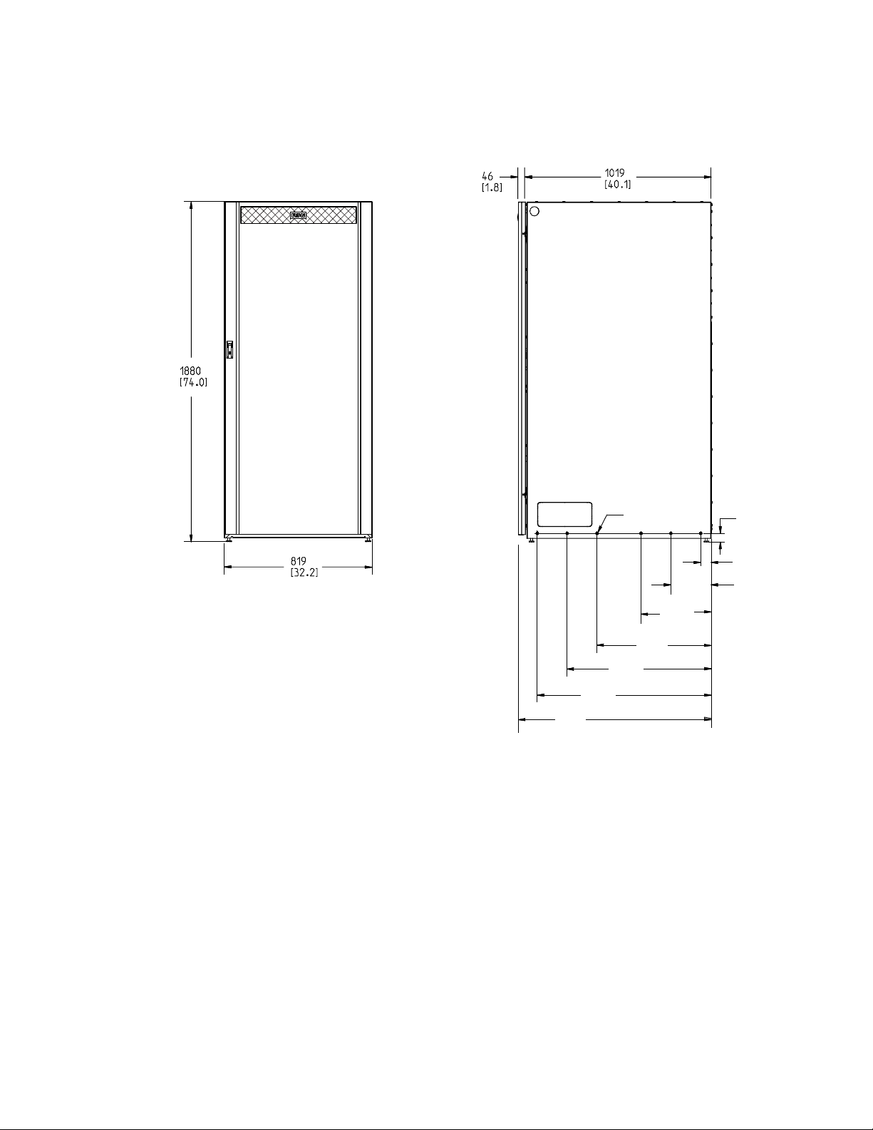
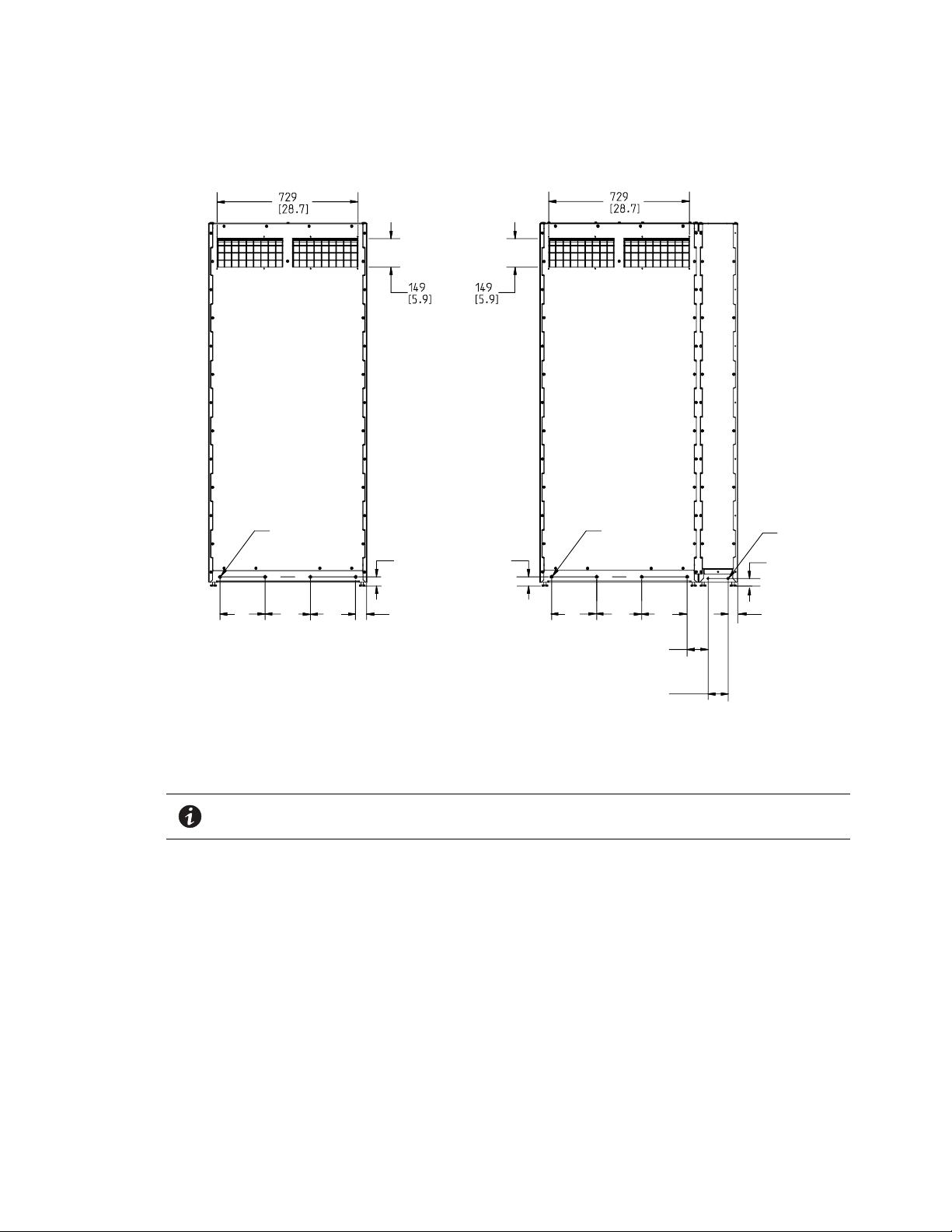
Figure 4. IBC-L or IBC-LH Dimensions (Front and Right Side Views)
1067
[42.0]
M10THD (12X)
6 EachSide
58
[2.3]
223
[8.8]
47
[1.9]
388
[15.3]
630
[24.8]
795
[31.3]
960
[37.8]
Dimensions are in millimeters [inches]
Installation Plan and Unpacking
Eaton 93PM Integrated Battery Cabinet (IBC-L, IBC-LH [432V], and IBC-LH [480V]) Installation Manual 164000228—Rev 08 17
M12THD (8X)
4
EA
FT&RR
M8
T
HD (4X
)
58
[2.3]
47
[1.9]
234
[9.2]
234
[9.2]
234
[9.2]
38.5
[1.5]
47
[1.9]
49.5
[2.0]
234
[9.2]
234
[9.2]
234
[9.2]
108
[4.3]
104
[4.1]
M12THD (8X)
4
EA
FT&RR
2
EA
FT&RR
Dimensions are in millimeters [inches]
IBC without Sidecar IBC with Sidecar
Installation Plan and Unpacking
Figure 5. IBC-L or IBC-LH Dimensions (Rear Views)
NOTE The sidecar is shown factory installed on the left side of the IBC. However, the sidecar
can be factory installed on the right side.
18 Eaton 93PM Integrated Battery Cabinet (IBC-L, IBC-LH [432V], and IBC-LH [480V]) Installation Manual 164000228—Rev 08
 Loading...