

Eaton 93PM-100(400), 93PM-250(400), 93PM-200(400), 93PM-350(400), 93PM-400(400) Safety And Installation Quick Manual
...
SAFETY AND INSTALLATION
QUICK GUIDE
P-16400 0667
Eaton 93PM UPS
100-500kVA
DOWNLOAD FULL USER’S AND INSTALLATION
GUIDE AT WWW.EATON.EU/93PM
0 ºC 10 ºC 20 ºC 30 ºC 40 ºC 50 ºC
7.3
7.3
7.1
93PM-xxx(400)
93PM-xxx(500)
1
2
7.2
BLUE BEADS IN
ARROW INDICATES
CONTAINER WAS
TIPPED OR
MISHANDLED
MADE IN U.S.A.
(1521 mm)
920 mm
(1120 mm)
1968 mm
1618 mm
1968 mm
(1120 mm)
920 mm
1618 mm
x2
7.7
1
2
3
%
100% 0 % 20 % 40% 60% 80 %
95 %
5 %
4
6.1
(1521 mm)
b
a
Rev. 2
5
1
2
3 6.2 7.8
7.4
7.67.5
9
14
11
13
8
5
12
6
7
2
10
1 2
8 4
9 10 6 7
3 5 11
1 2 3 4 5 6 7 8 9 10 11 12
<80°
1
2
3 4
1 2 3 4
123
123
NC
1 2 3 4
NO
4
1
3
2
7
6
5
11
10
9
8
11
12
13
1
2
3
4
5
7
8
9
10
1
2
3
4
5
6
NC NO
1 3 4
2
1
2
3
4
5
X6
B
C
A
5 4 3 2 1
3
4
5
6
7
8
9
10
2
1
14
13
8
9
10
15
16
CONTENTS
EN Safety and Installation Quick Guide
DE Schnellanleitung für Sicherheit und Installation
FR Guide rapide de sécurité et d’installation
FI Turvallisuus- ja asennuspikaopas
SV Snabbguide för säkerhet och installation
NO Hurtigveiledning for sikkerhets or installasjon
DA Hurtig sikkerheds- of installationsvejledning
RU Kpatkoe руководство по технике безопасности и установке
NL Verkorte handleidingvoor veiligheid en installatie
ES Guía rápida de instalación y seguridad
CS R ychlá bezpečnostní a instalační příručka
PL Skrócona instrukcja bezpieczeństwa i montażu
IT Guida rapida all’installazione e informazioni sulla sicurezza
. . . . . . . . . . . . . . . . . . . . . . . . . . . . . . . . . . . . 1
. . . . . . . . . . . . . . . . . . . . . . . 11
. . . . . . . . . . . . . . . . . . . . . . . . . . . . . 21
. . . . . . . . . . . . . . . . . . . . . . . . . . . . . . . . . . . . . 31
. . . . . . . . . . . . . . . . . . . . . . . . . . . . . 41
. . . . . . . . . . . . . . . . . . . . . . . . 51
. . . . . . . . . . . . . . . . . . . . . . . . . . 61
. . . . . . . . 71
. . . . . . . . . . . . . . . . . . . . 81
. . . . . . . . . . . . . . . . . . . . . . . . . . . . . . . . 91
. . . . . . . . . . . . . . . . . . . . . . . . . . . . . 101
. . . . . . . . . . . . . . . . . . . . . . 111
. . . . . . . . . . . 121
4
1
3
2
10
9
8
15
14
16
5
6
7
11
12
13
MBP
MIS
11
12
1
DANGER
Important safety instructions!
Keep these instructions!
This document provides important safety instructions and a short instruction for how to
examine the UPS delivery and how to install the UPS. This quick guide is only meant to be
used as an installation checklist on site.
The intended audience of this document is experienced professionals who plan and do the
installation of the UPS.
DANGER
Before you do work on the UPS, read the full installation instructions provided in the
Eaton 93PM UPS 100-500 kVA User’s and Installation Guide.
The full instructions are available for download at www.eaton.eu/93pm.
Operations inside the UPS must be done by an authorized Eaton Customer Service
Engineer or by qualified service personnel authorized by Eaton. There are no userserviceable parts inside the UPS.
The UPS operates with mains, battery or bypass power. It contains components that carry
high currents and voltage. A correctly installed enclosure is earthed and IP20 rated
against
electric shock and unwanted objects. The UPS is a sophisticated power system and only
qualified personnel are allowed to install and service it.
DANGER
This UPS carries lethal voltages.
Batteries present a risk of electrical shock or burn from high short circuit current. Obey
the precautions.
Batteries may contain HIGH VOLTAGES, and CORROSIVE, TOXIC and EXPLOSIVE
material. Because of the battery string the output receptacles may carry high voltage
even when the AC supply is not connected to the UPS. Read the shutdown
instructions in
the User’s and Installation Guide.
WARNING
The UPS is powered by its own energy source (batteries). The output terminals may be
energized even when the UPS is disconnected from an AC source. To reduce the risk of
fire or electric shock, install this UPS in a temperature and humidity controlled, indoor
environment that is free of conductive contaminants.
EN
11
WARNING
The ambient temperature limit must not be exceeded. Do not operate the UPS near water
or excessive humidity (95% maximum). The system is not intended for outdoor use.
Before you start any installation or service work, make sure that all AC and DC power
sources are disconnected. Power may come from multiple sources. Also ensure system
grounding / PE continuity.
In a parallel system, the output terminals may be energized even when the UPS is turned
off.
Electric energy hazard. To avoid injury, do not attempt to alter any battery wiring or
connectors.
IMPORTANT: Make sure that you disconnect all battery strings before installation.
CAUTION
Only qualified service personnel knowledgeable of batteries and the required precautions
can do installation or service work on batteries. Installation and service work on batteries
is live-line working and requires the use of voltage tools. Keep unauthorized personnel
away from the batteries.
Before you install or replace batteries, consider all the warnings, cautions, and notes
concerning appropriate handling. Do not disconnect the batteries when the UPS is in the
Battery mode.
Make sure that your replacement batteries are of the same number and type as the
battery that was originally installed in the UPS. See more accurate instructions on the
UPS.
Before you connect or disconnect battery terminals, disconnect the charging source by
opening the corresponding battery circuit breaker.
Examine if the battery is inadvertently grounded. If it is, remove the source of the ground.
Contacting any part of a grounded battery can cause a risk of electric shock.
Discard batteries according to your local disposal requirements.
Do not discard batteries in a fire. When exposed to flame, batteries may explode.
To reduce the risk of a fire, connect only to a circuit that is provided with maximum input
circuit breaker current ratings in accordance with the national and local installation rules.
To ensure proper cooling airflow and to protect personnel from dangerous voltages inside
the unit, keep the UPS door closed and the front panels installed.
Do not install or operate the UPS system close to gas or electric heat sources.
Keep the operating environment within the parameters stated in this document. Keep the
surroundings of the UPS uncluttered, clean, and free from excess moisture.
Obey all DANGER, CAUTION, and WARNING notices affixed to the inside and outside of
the equipment.
EN
22
2
The Eaton® 93PM uninterruptible power supply (UPS) is a true online, continuous-duty,
transformerless, double-conversion, solid-state, three-phase system that supplies
conditioned and uninterruptible AC power to critical load and protects it from power
failures. Eaton 93PM output power ratings are based on 50 kVA and 62,5 kVA rated
uninterruptible power modules (UPMs). A single UPS cabinet can house from two to eight
UPMs to get ratings of 100 to 400 kVA with 50 kVA module, and 100 to 500 kVA with 62,5
kVA module.
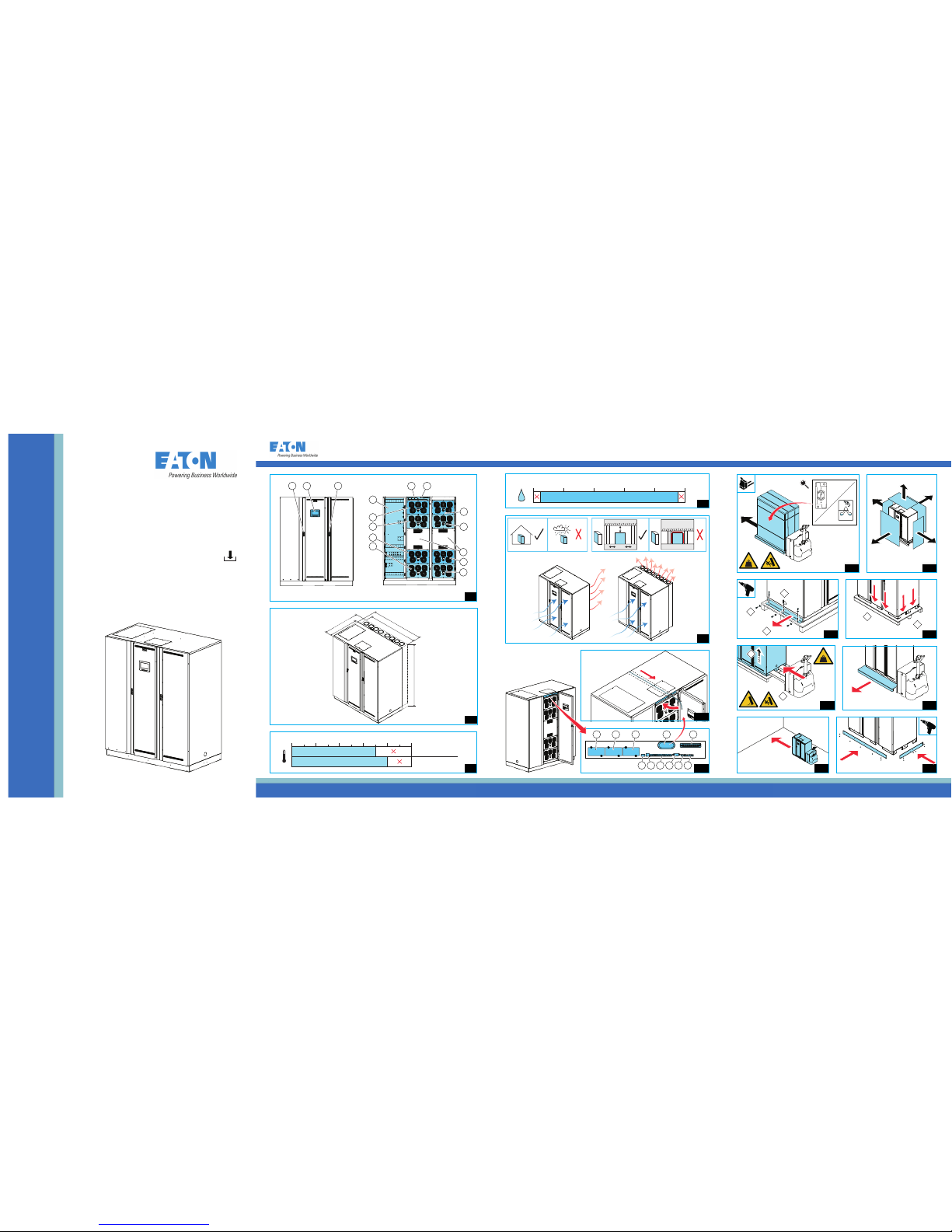
The main parts of the 93PM UPS 100-500 kVA are shown in illustration 1. The main parts
are:
1. Control panel
2. Door latch
3. Communications area
4. Communication cable conduit
5. Connector area
6. UPM 1
7. UPM2
8. UPM 3
9. UPM 4
10. UPM 5
11. UPM 6
12. UPM 7
13. UPM 8
14. Static switch
.
DANGER
This UPS carries lethal voltages.
Operations inside the UPS must be done by an authorized Eaton Customer Service
Engineer or by qualified service personnel authorized by Eaton. There are no userserviceable parts inside the UPS.
For complete safety instructions, refer to the Eaton 93PM UPS 100-500 kVA User’s and
Installation Guide.
The UPS must be installed according to the recommendations in the Eaton 93PM UPS
100-500 kVA User’s and Installation Guide.
The recommended ambient operating temperature and humidity for the UPS system is
shown in illustrations 3 and 4. An ambient temperature from +20…25 °C is recommended
to achieve a long life of VRLA batteries.
Use the following basic sequence of steps to install the UPS:
1. Make an installation plan for the UPS system.
2. Prepare your site for the UPS system.
3. Inspect and unpack the UPS cabinet.
4. Unload and install the UPS cabinet and wire the system.
5. Complete the installation checklist.
6. Have authorized service personnel do the preliminary operational checks and start-up.
EN
33
NOTE: Startup and operational checks must be done by an authorized Eaton Customer
Service Engineer or by qualified service personnel authorized by Eaton, or the warranty
terms specified in the Warranty become void.
Before you install the UPS system, read and understand how these instructions apply to
the system that you are going to install. Use the procedures and illustrations provided to
make a logical plan for installing the system.
For the UPS system to operate at peak efficiency, the installation site must meet the
environmental parameters outlined in the Eaton 93PM UPS 100-500 kVA User’s and
Installation Guide.
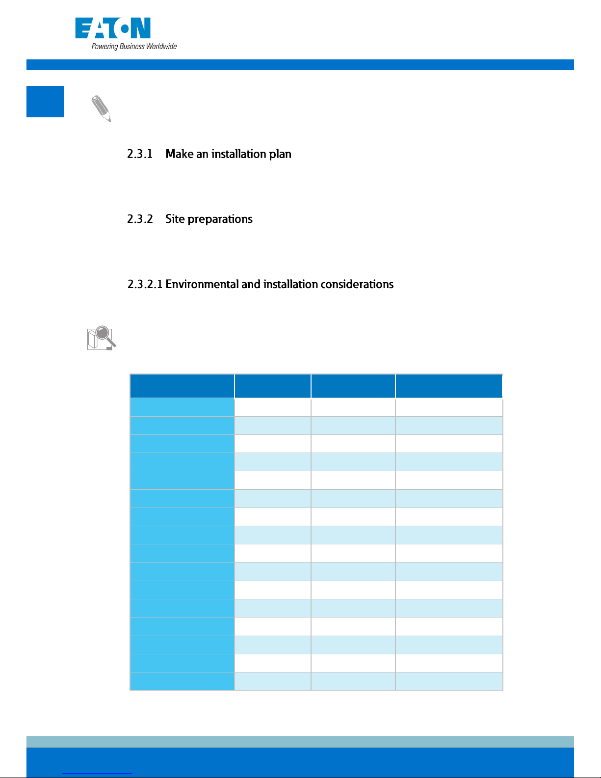
The installation environment must meet the UPS weight and size requirements provided in
Tables 1 and 2.
The dimensions of the UPS cabinet are shown in illustration 2. Note that the depth
dimension includes cable glands.
Table 1. UPS cabinet weights with cardboard packaging
UPS model
Shipping weight
[kg]
Installed weight
[kg]
Floor loading [kg/m2]
93PM-100(400)
720 680 439
93PM-150(400)
785 745 540
93PM-200(400)
850 810 587
93PM-250(400)
915 875 635
93PM-300(400)
980 940 682
93PM-350(400)
1045 1005 729
93PM-400(400)
1110 1070 776
93PM-100(500) 720 680 439
93PM-150(500)
785 745 540
93PM-200(500)
850 810 587
93PM-250(500)
850 810 587
93PM-300(500)
915 875 635
93PM-350(500)
980 940 682
93PM-400(500)
1045 1005 729
93PM-450(500)
1110 1070 776
93PM-500(500)
1110 1070 776
EN
44
The UPS cabinets use forced air cooling to regulate internal component temperature. By
default, air inlets are in the front of the cabinet and outlets are in the rear, see illustration 5.
Allow clearance in front of and behind each cabinet for proper air circulation. With the
optional top air exhaust kit, it is possible to configure the air outlets in the top rear of the
cabinet. With this option, the UPS can be installed against a wall or back-to-back. Make
sure that the cooling air that enters the UPS does not exceed the specified maximum
ambient temperature. For ventilation requirements, refer to the Eaton 93PM UPS 100-500
kVA User’s and Installation Guide.
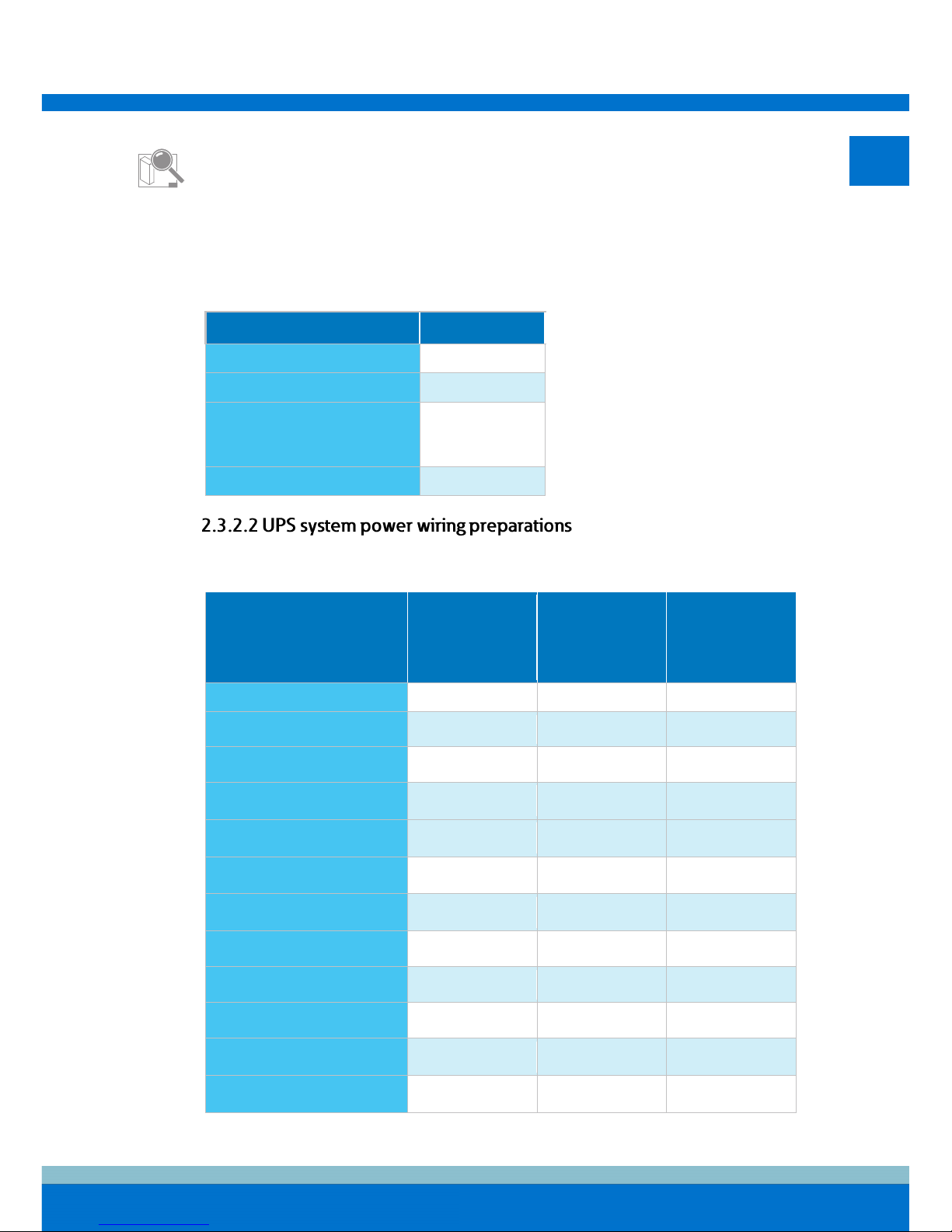
Table 2. UPS cabinet minimum clearances
From the top of the cabinet
500 mm
From the front of the cabinet
900 mm
From the rear of the cabinet
*) 0 mm if top air exhaust kit
installed
450 mm*
From the side of the cabinet
0 mm
Table 3. Minimum recommended multi-core cable and fuse sizes for rectifier and bypass input and
UPS output cables
UPS model Phase cables
Rectifier, static
bypass and
maintenance
bypass input
fuse [A]
PE cable [mm2]
93PM-100(400)
95 mm
2
200 50
93PM-150(400)
185 mm2 315 95
93PM-200(400)
240 mm2 400 120
93PM-250(400)
2 x 120 mm2 per
phase
500 120
93PM-300(400)
2 x 185 mm2 per
phase
630 185
93PM-350(400)
2 x 240 mm2 per
phase
700 240
93PM-400(400)
2 x 240 mm2 per
phase
800 240
93PM-100(500)
95 mm2 200 50
93PM-150(500)
185 mm2 315 95
93PM-200(500)
240 mm2 400 120
93PM-250(500)
2 x 120 mm2 per
phase
500 120
93PM-300(500)
2 x 120 mm2 per
phase
500 120
EN
55
UPS model Phase cables
Rectifier, static
bypass and
maintenance
bypass input
fuse [A]
PE cable [mm2]
93PM-350(500)
2 x 185 mm2 per
phase
630 185
93PM-400(500)
2 x 240 mm2 per
phase
800 240
93PM-450(500)
2 x 240 mm2 per
phase
800 240
93PM-500(500)
) 2 x 240 mm2 per
phase
800
240
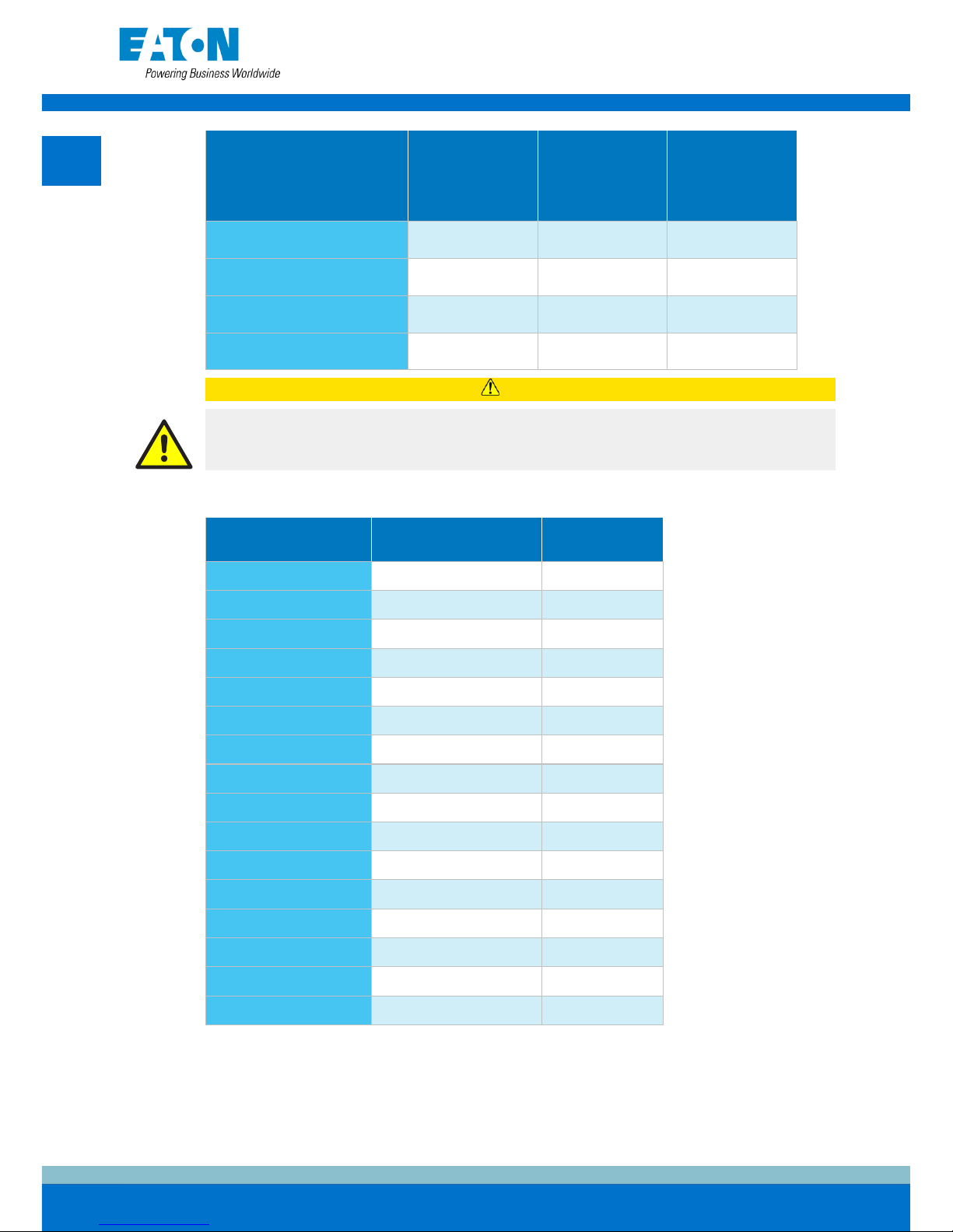
CAUTION
Make sure that prospective short-circuit current resulting at the UPS input terminals is
equal or less than conditional short-circuit current declared on the type plate of the UPS.
Table 4. Minimum recommended cable and fuse sizes for external battery bank
UPS model
Battery cable, pos. &
neg. line
Battery fuse [A]
93PM-100(400)
185 mm
2
per pole 315
93PM-150(400)
240 mm2 per pole
400
93PM-200(400)
2 x 185 mm2 per pole
630
93PM-250(400)
2 x 240 mm2 per pole
700
93PM-300(400)
2 x 240 mm2 per pole
800
93PM-350(400)
4 x 120 mm2 per pole
1000
93PM-400(400)
4 x 185 mm2 per pole
1250
93PM-100(500)
120 mm2 per pole
250
93PM-150(500)
240 mm2 per pole
400
93PM-200(500)
2 x 120 mm2 per pole
500
93PM-250(500)
2 x 185 mm2 per pole
630
93PM-300(500)
2 x 240 mm2 per pole
800
93PM-350(500)
4 x 120 mm2 per pole
1000
93PM-400(500)
4 x 120 mm2 per pole
1000
93PM-450(500)
4 x 185 mm2 per pole
1250
93PM-500(500)
4 x 185 mm2 per pole
1250
Refer to national and local electrical codes for acceptable external wiring practices.
For information on rated and maximum currents for rated power and voltage, refer to the
Eaton 93PM UPS 100-500 kVA User’s and Installation Guide.
For the battery terminals in the 93PM with a separate battery option, refer to the Eaton
93PM UPS 100-500 kVA User’s and Installation Guide.
EN
66

NOTE: External overcurrent protection is not provided by this product, but is required by
codes. Refer to Table 3 and Table 4 for wiring requirements. If a lockable output
disconnect is required, it must be supplied by the user.
Table 5. UPS power cable terminal torques
Function Tightening torque [Nm] Bolt size
Phases
80
M12
Neutral and PE (ground) 47 M10
Action
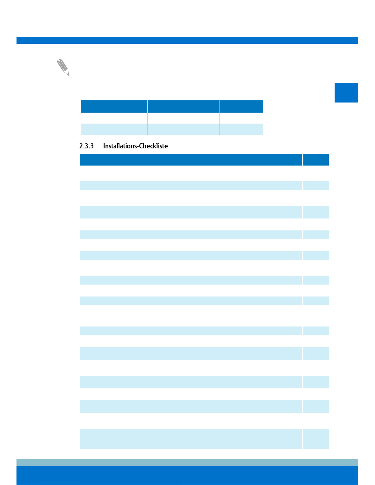
Yes/No
All packing materials and restraints are removed from each cabinet.
Each cabinet in the UPS system is placed in its installed location.
A cabinet grounding kit / mounting kit is installed between any cabinets that are bolted
together.
All conduits and cables are properly routed to the UPS and any ancillary cabinets.
All power cables are properly sized and terminated.
Neutral conductors are installed and bonded to ground according to the requirements.
A ground conductor is properly installed.
Battery cables are terminated and connected to battery connectors.
Battery Shunt trip and Aux contact signal wiring is connected from the UPS to the battery
breaker.
LAN drops are installed.
All LAN connections are completed.
Air conditioning equipment is installed and operating correctly.
The area around the installed UPS system is clean and dust-free (it is recommended that
the UPS is installed on a level floor suitable for computer or electronic equipment).
There is adequate workspace around the UPS and other cabinets.
Adequate lighting is provided around all the UPS equipment.
A 230 VAC service outlet is located within 7.5 meters of the UPS equipment.
The Remote Emergency Power-off (REPO) device is mounted in its installed location and
its wiring is terminated inside the UPS cabinet.
If EPO is used in the NC configuration, a jumper is installed on the EPO between pins 1
and 2.
(OPTIONAL) Alarm relays and signal outputs are wired appropriately.
(OPTIONAL) A remote battery disconnect control is mounted in its installed location and
its wiring is terminated inside the UPS and battery cabinet.
(OPTIONAL) Accessories are mounted in their installed locations and their wiring is
terminated inside the UPS cabinet.
Start-up and operational checks are done by an authorized Eaton Customer Service
Engineer or by a qualified service engineer authorized by Eaton.
EN
77
The unpacking and unloading of the UPS is shown in illustrations 7.1–7.8.
Before you start to unpack and unload the UPS, examine the TipNTell and DropNTell
indicators on the package surface. If the equipment has been correctly transported in the
upright position, the indicators should be intact. If the TipNTell indicator arrow has turned
all blue or the arrow head(s) of the DropNTell indicator are black, contact the appropriate
parties to report inappropriate transportation.
For transportation purposes, the UPS cabinet is bolted onto a wooden pallet. Before you
unload the cabinet from the pallet, use a forklift or other material handling equipment to
move the cabinet to the installation area.
WARNING
The UPS cabinet is heavy. If the unpacking instructions are not closely followed, the
cabinet may tip over and cause serious injury.
Do not tilt the UPS cabinet more than 10 degrees from the vertical or the cabinet may tip
over.
NOTE: After you have removed the shipping brackets, move the unit immediately away
from the pallet.
If you remove the cabinet from its original installation location and transfer it to a new
location on a pallet, attach the shipping brackets or the lower cover plates to the cabinet
and the pallet.
The operator must supply the wiring to connect the UPS to the local power source. The
installation of the UPS must be done by a locally qualified electrician. The installation
inspection and the initial start-up of the UPS and installing an extra battery cabinet must be
carried out by an authorized Eaton Customer Service Engineer or by a qualified service
personnel authorized by Eaton.
If you are installing a 93PM with a separate battery option, refer to the Eaton 93PM UPS
100-500 kVA User’s and Installation Guide.
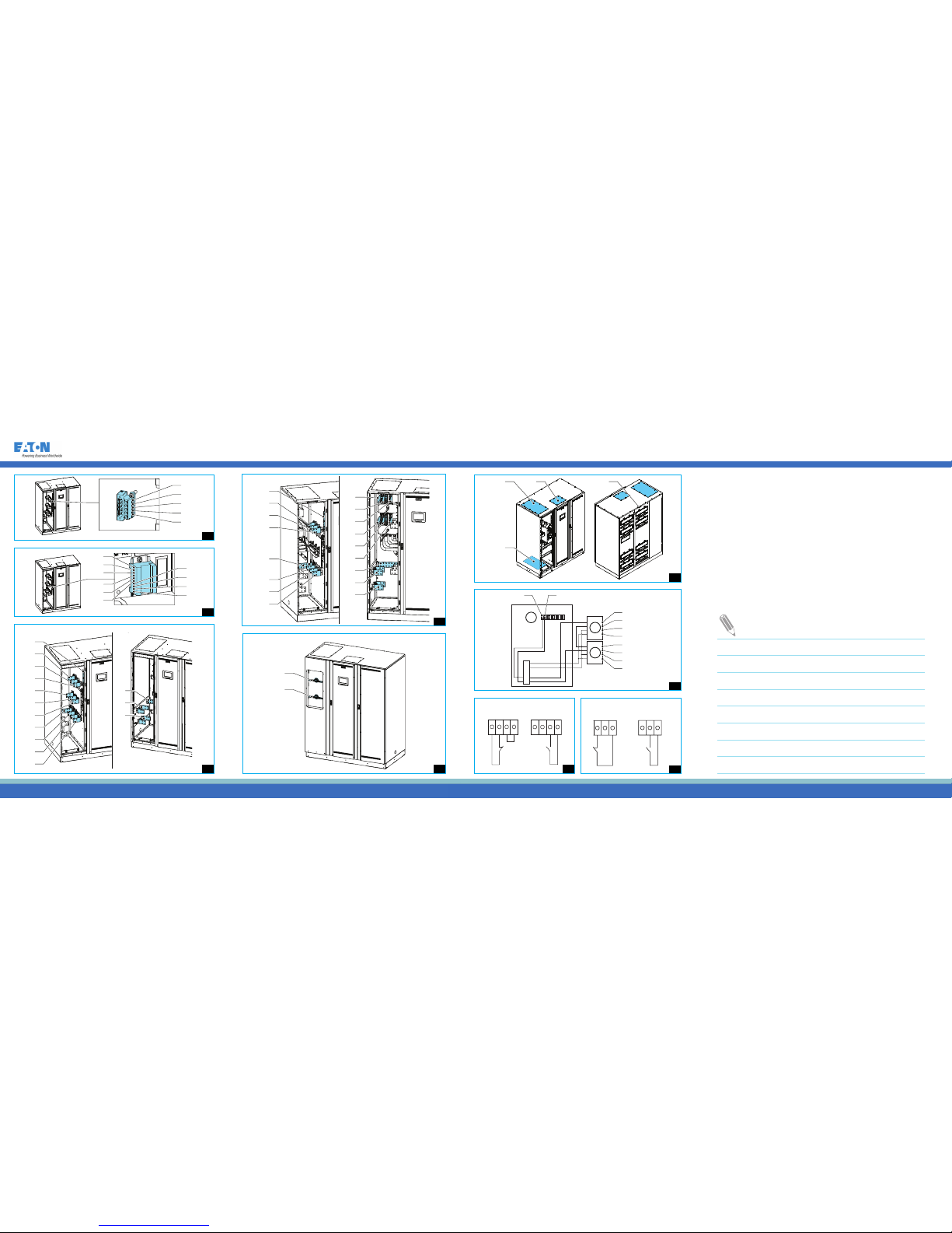
The battery trip wiring X6 is shown in illustration 8.
1
Shunt trip (+24 V C1)
2
Shunt trip return (TRIP C2)
3
Not in use
4
Status signal (DET 3.14)
5
Status signal return (GND
3.13)
Sync control interface X11 details are shown in illustration 9.
1
Bypass L1
6
Out L3
2
Bypass L2
7
Not in use
3
Bypass L3
8
Sync signal in L1
4
Out L1
9
Sync signal in L2
5
Out L2
10
Sync signal in L3
EN
88
The connector locations are shown in illustration 10.
1. Ground
2. X1:L1 Rectifier input L1
3. X1:L2 Rectifier input L2
4. X1:L3 Rectifier input L3
5. X3:L1 UPS Output L1
6. X3:L2 UPS Output L2
7. X3:L3 UPS Output L3
8. X2:L1 Bypass input L1
9. X2:L2 Bypass input L2
10. X2:L3 Bypass input L3
11. X1/X2/X3:N Neutral
12. X4:BATT+ External
battery +
13. X4:BATT- External
battery -
The connector locations of the UPS with the optional internal MBS switch are shown in
illustration 11.
1. Ground
2. X1:L1 Rectifier input L1
3. X1:L2 Rectifier input L2
4. X1:L3 Rectifier input L3
5. X3:L1 UPS Output L1
6. X3:L2 UPS Output L2
7. X3:L3UPS Output L3
8. X2:L1 Bypass input L1
9. X2:L2 Bypass input L2
10. X2:L3 Bypass input L3
11. X1/X2/X3/X7:N Neutral
12. X4:BATT+ External
battery +
13. X4:BATT- External
battery –
14. X8:L1 Maintenance
bypass input L1
15. X8:L2 Maintenance
bypass input L2
16. X8:L3 Maintenance
bypass input L3
The MBP and MIS switches are shown in illustration 12.
The UPS gland plates are shown in illustration 13.
1
Top cable access gland plate
2
Bottom cable access gland plate
3
Top signal wiring access gland plate
4
Cable conduit
See illustrations 6.1 and 6.2 for the UPS communication terminals and communication
cable routing instructions. The terminals are:
1. MiniSlot 1
2. MiniSlot 2
3. MiniSlot 3
4. USB device (connection
to computer)
5. Communication cable
conduit
6. Emergency Power Off,
EPO
7. Relay output
8. USB host (connection to
accessories)
9. Signal inputs
10. RS-232 port for service
11. External parallel connector
If installing a customer-supplied battery system, install the battery system according to the
battery and battery system manufacturer’s instructions and all the applicable national
codes and regulations.
For the battery specification, refer to the Eaton 93PM UPS 100-500 kVA User’s and
Installation Guide.
The external battery breaker is a crucial part of the external battery cabinet or rack and
must be placed in it. With the external battery breaker, signal cabling is required for safe
operation of the UPS.
The external battery breakers can be tripped (switched off) by energizing its shunt trip
coils. The shunt trip coils are energized (controlled) through connector X6. The default
voltage of the battery breaker shunt trip coil is 24 Vdc.
EN
99

Battery trip wiring is shown in illustration 14. The parts are:
A
Signal inputs
4
Aux contact
B
External battery breaker
5
Shunt trip coil -
C
External battery breaker
6
Shunt trip coil +
7
Aux contact return
1
Signal input 5 return
8
Aux contact
2
Signal input 5
9
Shunt trip coil -
3
Aux contact return
10
Shunt trip coil +
For instructions on how to install the external battery cabinet and battery power cabling,
see the Eaton 93PM UPS 100-500 kVA User’s and Installation Guide and the instruction
manual provided with the external battery cabinet. Earth the external battery cabinet /
customer-supplied battery system to the PE terminal 7.
EPO is connected to the UPS's top front panel, on connector EPO. The connections of the
EPO switch are shown in illustration 15.
For information on installing interface connections, refer to the Eaton 93PM UPS 100-500
kVA User’s and Installation Guide.
One general purpose relay contact is provided as a standard feature on the UPS. An alarm
contact is also provided. The output relay configurations are shown in illustration 16.
You can use a normally-closed or normally-open contact. If the state of the contact
changes from the state you specify as normal, a signal is issued. You can connect this
contact to equipment at your facility (such as a light or an alarm bell) to let you know when
an alarm is active on the UPS.
NOTE: Contacts should not be operated in excess of 30 VAC (RMS) and 30 VDC at 5 A
maximum.
For information on wiring parallel 93PM UPS systems, refer to the Eaton 93PM UPS 100500 kVA User’s and Installation Guide.
EN
1010
DE
11
1
GEFAHR
Wichtige Sicherheitsanweisungen!
Bewahren Sie diese Hinweise sicher auf!
Dieses Dokument enthält wichtige Sicherheitsanweisungen und eine Kurzanleitung dazu,
wie die Lieferung der USV überprüft und installiert wird. Diese Kurzanleitung dient
ausschließlich der Verwendung als Installationscheckliste vor Ort.
Die Zielgruppe dieses Dokuments sind erfahrene Fachleute, welche die Installation der
USV planen und durchführen.
GEFAHR
Bevor Sie die Arbeiten an der USV aufnehmen, lesen Sie die Installationsanweisungen
aus dem Benutzer- und Installationshandbuch der Eaton 93PM USV 100-500 kVA
vollständig durch.
Die vollständige Anleitung kann unter www.eaton.eu/93pm heruntergeladen werden.
Arbeiten in der USV müssen von einem autorisierten Eaton-Kundendienstmitarbeiter
oder von Kundendienstpersonal ausgeführt werden, das von Eaton qualifiziert wurde. Die
USV enthält keine Teile, die vom Benutzer gewartet werden müssen.
Die USV arbeitet mit Stromnetz, Batterie oder Bypass. Sie enthält Komponenten, die hohe
Ströme und Spannungen führen. Ein ordnungsgemäß installiertes Gehäuse ist geerdet und
nach IP20 gegen Stromschlag und Fremdkörper ausgelegt. Die USV ist ein
leistungsstarkes Stromversorgungssystem und sollte nur von qualifiziertem Personal
installiert und gewartet werden.
GEFAHR
Diese USV führt tödliche Spannungen.
Batterien stellen eine Gefahr durch Elektroschocks oder Verbrennungen durch
Kurzschlussstrom dar. Halten Sie die Sicherheitsvorkehrungen ein.
Batterien können HOHE SPANNUNGEN und KORRODIERENDE, GIFTIGE und
EXPLOSIVE Materialien enthalten. Aufgrund der Batteriestränge können die
Ausgangsstecker hohe Spannungen aufweisen, auch wenn die AC-Versorgung nicht an
der USV angeschlossen ist. Lesen Sie die Abschaltungsanleitungen im Benutzer- und
Installationshandbuch.
ACHTUNG
Die USV wird durch die systemeigene Energiequelle (Batterien) mit Strom versorgt. Die
Ausgangsanschlüsse können auch unter Spannung stehen, wenn die USV von der
Wechselstromquelle getrennt ist. Um das Risiko eines Brandes oder Stromschlags zu
minimieren, installieren Sie diese USV in einem temperatur- und feuchtigkeitsgeregelten
Innenraum, der frei von leitenden Verunreinigungen ist.
11
DE
12
ACHTUNG
Die Umgebungstemperaturgrenze darf nicht überstiegen werden. Betreiben Sie die USV
nicht in der Nähe von Wasser oder hoher Feuchtigkeit (maximal 95 %). Das System ist
nicht für den Einsatz im Freien geeignet.
Bevor Sie mit Installations- oder Wartungsarbeiten beginnen, stellen Sie sicher, dass alle
Wechsel- und Gleichstromquellen getrennt wurden. Der Strom kann von verschiedenen
Quellen stammen. Achten Sie auch darauf, dass das System geerdet ist / PE-Durchgang
hat.
In einem Parallelsystem können die Ausgangsanschlüsse auch unter Spannung stehen,
wenn die USV abgeschaltet ist.
Stromschlaggefahr. Um Verletzungen zu verhindern, führen Sie unter keinen Umständen
Änderungen an der Batterieverkabelung oder den Anschlüssen durch.
WICHTIG: Vergewissern Sie sich vor der Installation, dass Sie alle Batteriestränge
getrennt haben.
VORSICHT
Nur qualifiziertes Servicepersonal, das Kenntnisse über Batterien und die erforderlichen
Sicherheitsvorkehrungen hat, darf Installations- oder Servicearbeiten an Batterien
durchführen. Benutzen Sie bei Montage- und Wartungsarbeiten an Batterien geeignetes
Werkzeug für Arbeiten an spannungsführenden Teilen. Halten Sie nicht autorisierte
Personen von den Batterien fern.
Bevor Sie Batterien einbauen oder austauschen, beachten Sie alle Warnungen,
Vorsichtsmaßnahmen und Hinweise über eine angemessene Handhabung. Trennen Sie
die Batterien nicht, wenn sich die USV im Batteriemodus befindet.
Stellen Sie sicher, dass Ihre Austauschbatterien die gleiche Nummer haben und vom
gleichen Typ sind, wie die ursprünglich in der USV installierte Batterie. Genauere
Anweisungen finden Sie auf der USV.
Bevor Sie Batterieanschlüsse verbinden oder trennen, trennen Sie die Ladequelle, indem
Sie den entsprechenden Batteriestromkreistrenner öffnen.
Prüfen Sie, ob die Batterie versehentlich geerdet wurde. Ist dies der Fall, beseitigen Sie
die Erdungsverbindung. Die Berührung von Teilen einer geerdeten Batterie kann zu
Stromschlag führen.
Entsorgen Sie Batterien gemäß den regionalen Entsorgungsbestimmungen.
Werfen Sie die Batterien auf keinen Fall in ein Feuer. Batterien können explodieren,
wenn Sie Flammen ausgesetzt werden.
Um die Brandgefahr zu verringern, verbinden Sie ausschließlich mit einem Stromkreis,
der mit Eingangssicherungen mit den maximalen Nennströmen gemäß den nationalen
und lokalen Installationsvorschriften ausgestattet ist.
Um einen angemessenen Kühlluftstrom sicherzustellen, um Personen vor gefährlichen
Spannungen innerhalb der Einheit zu schützen, halten Sie die USV-Tür geschlossen und
die Frontplatten angebracht.
Vermeiden Sie die Platzierung bzw. den Betrieb des USV-Systems in der Nähe von Gas
oder elektrischen Wärmequellen.
Halten Sie die Betriebsumgebung innerhalb der in diesem Dokument angegebenen
Parameter. Stellen Sie sicher, dass die Umgebung der USV ordentlich, sauber und frei
von übermäßiger Feuchtigkeit ist.
Befolgen Sie alle GEFAHR-, VORSICHT- UND ACHTUNG-Hinweise, die innen und
außen an der Anlage angebracht sind.
12
DE
13
2
Bei der unterbrechungsfreien Stromversorgung (USV) Eaton® 93PM handelt es sich um
ein echtes transformatorloses Online-Drehstromsystem mit DoppelwandlerHalbleitertechnologie, das im Dauerbetrieb einen aufbereiteten und unterbrechungsfreien
Wechselstrom liefert, um kritische Verbraucher vor Stromausfällen zu schützen. Die
Ausgangsnennleistungen der Eaton 93PM basieren auf den auf 50 kVA und 62.5 kVA
ausgelegten unterbrechungsfreien Leistungsmodulen (UPM). Ein einzelner USV-Schrank
kann zwischen zwei und acht UPMs beherbergen, um Leistungen von 100 bis 400 kVA mit
einem 50 kVA Modul und 100 bis 500 kVA mit einem 62,5 kVA Modul zu erzielen.
Die Hauptteile der 93PM USV 100-500 kVA sind in Abbildung 1 dargestellt. Die Hauptteile
sind folgende:
1. Bedienfeld
2. Türriegel
3. Kommunikationsbereich
4. Kommunikationskabeldurchführung
5. Anschlussbereich
6. UPM 1
7. UPM 2
8. UPM 3
9. UPM 4
10. UPM 5
11. UPM 6
12. UPM 7
13. UPM 8
14. Statischer Bypass
.
GEFAHR
Diese USV führt tödliche Spannungen.
Arbeiten in der USV müssen von einem autorisierten Eaton-Kundendienstmitarbeiter
oder von Kundendienstpersonal ausgeführt werden, das von Eaton qualifiziert wurde. Die
USV enthält keine Teile, die vom Benutzer gewartet werden müssen.
Für die vollständigen Sicherheitsanweisungen, siehe das Benutzer- und
Installationshandbuch für die Eaton 93PM USV 100-500 kVA.
Die USV muss gemäß den Empfehlungen des Benutzer- und Installationshandbuchs für
die Eaton 93PM USV 100-500 kVA installiert werden.
Die empfohlene Umgebungsbetriebstemperatur und Luftfeuchtigkeit für das USV-System
ist in Abbildung 3 und 4 dargestellt. Eine Umgebungstemperatur von +20 °C bis 25 °C wird
empfohlen, um eine lange Lebensdauer der VRLA-Batterien zu erzielen.
Halten Sie sich zur Installation der USV an die folgende grundsätzliche Reihenfolge der
Schritte:
1. Erstellen Sie einen Installationsplan für das USV-System.
2. Bereiten Sie Ihren Standort für das USV-System vor.
3. Überprüfen und packen Sie den USV-Schrank aus.
4. Entladen und installieren Sie den USV-Schrank und verkabeln Sie das System.
5. Vervollständigen Sie die Installations-Checkliste.
6. Lassen Sie autorisiertes Servicepersonal die Vorab-Betriebskontrollen durchführen und
das System in Betrieb nehmen.
13
DE
14
HINWEIS: Kontrollen bei der Inbetriebnahme oder während des Betriebs müssen von
einem autorisierten Eaton-Kundendienstmitarbeiter oder durch qualifiziertes, von Eaton
autorisiertes Wartungspersonal durchgeführt werden, andernfalls werden die in der
Garantie angegebenen Garantiebedingungen ungültig.
Vor der Installation des USV-Systems lesen Sie diese Anweisungen und verstehen Sie,
wie sie auf das zu installierende System anzuwenden sind. Verwenden Sie die
angegebenen Abläufe und Abbildungen, um einen logischen Plan für die Installation des
Systems zu erstellen.
Damit das USV-System mit höchster Effizienz läuft, muss der Installationsstandort die
Umgebungsparameter erfüllen, die im Benutzer- und Installationshandbuch für die Eaton
93PM USV 100-500 kVA aufgeführt sind.
Die Installationsumgebung muss den Gewichts- und Größenanforderungen der USV laut
Tabelle 1 und 2 entsprechen.
Die Abmessungen des USV-Schranks sind in Abbildung 2 dargestellt. Beachten Sie, dass
die Tiefenabmessungen Kabeleinführungen enthalten.
Tabelle 1. Gewichte des USV-Schranks mit Kartonverpackung
USV-Modell
Versandgewicht
[kg]
Montagegewicht
[kg]
Bodenbelastung
[kg/m2]
93PM-100(400)
720 680 439
93PM-150(400)
785 745 540
93PM-200(400)
850 810 587
93PM-250(400)
915 875 635
93PM-300(400)
980 940 682
93PM-350(400)
1045 1005 729
93PM-400(400)
1110 1070 776
93PM-100(500)
720 680 439
93PM-150(500)
785 745 540
93PM-200(500)
850 810 587
93PM-250(500)
850 810 587
93PM-300(500)
915 875 635
93PM-350(500)
980 940 682
93PM-400(500)
1045 1005 729
93PM-450(500)
1110 1070 776
93PM-500(500)
1110 1070 776
14
DE
15
Die USV-Schränke verwenden Zwangsluftkühlung, um die Innentemperatur der
Komponenten zu regulieren. Standardmäßig befinden sich Lufteinlässe in der Vorderseite
des Schranks und Auslässe in der Rückseite; siehe Abbildung 5. Lassen Sie für eine
ordnungsgemäße Luftzirkulation einen Abstand vor und hinter jedem Schrank. Mit dem
optionalen Top Air Exhaust Kit wird es möglich, die Luftauslässe an der oberen Rückseite
des Schranks zu konfigurieren. Bei dieser Variante können die USV gegen eine Wand
oder mit dem Rücken gegeneinander montiert werden. Stellen Sie sicher, dass die
Kühlluft, die in die USV einströmt, nicht die vorgegebene maximale Umgebungstemperatur
übersteigt. Für die Belüftungsanforderungen, siehe das Benutzer- und
Installationshandbuch für die Eaton 93PM USV 100-500 kVA.
Tabelle 2. Mindestabstände für USV-Schränke
Von der Oberseite des Schranks
500 mm*
Von der Vorderseite des Schranks
900 mm*
Von der Rückseite des Schranks
*) 0 mm, wenn das Top Air Exhaust Kit installiert ist
450 mm*
Von der Seite des Schranks
0 mm*
Tabelle 3. Mindestanforderungen an das Mehrleiterkabel und die Dimensionierung der Sicherungen
für den Gleichrichter und den Bypass-Eingang sowie für die USV-Ausgangskabel
USV-Modell Phasen-Kabel
Gleichrichter,
statischer Bypass und
Wartungsbypass-
Eingangssicherung [A]
PE-Kabel [mm2]
93PM-100(400)
95 mm
2
200 50
93PM-150(400)
185 mm2 315 95
93PM-200(400)
240 mm2 400 120
93PM-250(400)
2 x 120 mm2 pro Phase 500 120
93PM-300(400)
2 x 185 mm2 pro Phase 630 185
93PM-350(400)
2 x 240 mm2 pro Phase 700 240
93PM-400(400)
2 x 240 mm2 pro Phase 800 240
93PM-100(500)
95 mm2 200 50
93PM-150(500)
185 mm2 315 95
93PM-200(500)
240 mm2 400 120
93PM-250(500)
2 x 120 mm2 pro Phase 500 120
93PM-300(500)
2 x 120 mm2 pro Phase 500 120
93PM-350(500)
2 x 185 mm2 pro Phase 630 185
15
DE
16
USV-Modell Phasen-Kabel
Gleichrichter,
statischer Bypass und
Wartungsbypass-
Eingangssicherung [A]
PE-Kabel [mm2]
93PM-400(500)
2 x 240 mm2 pro Phase 800 240
93PM-450(500)
2 x 240 mm2 pro Phase 800 240
93PM-500(500)
2 x 240 mm2 pro Phase 800 240
VORSICHT
Stellen Sie sicher, dass der voraussichtliche Kurzschlussstrom, der an den
Eingangsanschlüssen der USV auftritt, gleich oder geringer ist als der bedingte
Kurzschlussstrom, der auf dem Typenschild der USV angegeben ist.
Tabelle 4. Empfohlene Mindestkabelstärken und Sicherungsstärken für externe Batteriebank
USV-Modell
Batteriekabel, Plus- & Minus-
Leitung
Batterie-
sicherung [A]
93PM-100(400)
185 mm
2
pro Pol 315
93PM-150(400)
240 mm2 pro Pol 400
93PM-200(400)
2 x 185 mm
2
pro Pol 630
93PM-250(400)
2 x 240 mm2 pro Pol 700
93PM-300(400)
2 x 240 mm
2
pro Pol 800
93PM-350(400)
4 x 120 mm2 pro Pol 1000
93PM-400(400)
4 x 185 mm
2
pro Pol 1250
93PM-100(500)
120 mm2 pro Pol 250
93PM-150(500)
240 mm
2
pro Pol 400
93PM-200(500)
2 x 120 mm2 pro Pol 500
93PM-250(500)
2 x 185 mm
2
pro Pol 630
93PM-300(500)
2 x 240 mm2 pro Pol 800
93PM-350(500)
4 x 120 mm
2
pro Pol 1000
93PM-400(500)
4 x 120 mm2 pro Pol 1000
93PM-450(500)
4 x 185 mm
2
pro Pol 1250
93PM-500(500)
4 x 185 mm2 pro Pol 1250
Die einzuhaltenden Normen für die externe Verkabelung entnehmen Sie bitte den
nationalen und lokalen Vorschriften.
Für Informationen zu Nenn- und Maximalströmen, Nennleistung und Spannung, siehe das
Benutzer- und Installationshandbuch für die Eaton 93PM USV 100-500 kVA.
Für Informationen zu den Batterieklemmen am Modell 93PM mit Batterieoption, siehe das
Benutzer- und Installationshandbuch für die Eaton 93PM USV 100-500 kVA.
16
DE
17
HINWEIS: Externer Überstromschutz wird durch dieses Produkt nicht geboten, ist aber
vorschriftsmäßig erforderlich. Anforderungen für die Verkabelung siehe Tabelle 3 und
Tabelle 4. Wenn ein abschließbarer Ausgangstrenner erforderlich ist, muss er vom
Benutzer bereitgestellt werden.
Tabelle 5. Anzugsmomente der USV-Hauptstromkabelanschlüsse
Funktion Anzugsdrehmoment [Nm] Bolzengröße
Phasen 80 M12
Neutral und PE (Erde) 47 M10
Aktion Ja/Nein
Sämtliche Verpackungsmaterialien und -arretierungen wurden von jedem Schrank
entfernt.
Jeder Schrank im USV-System ist an seiner vorgesehenen Position platziert.
Zwischen Schränken, die miteinander verschraubt werden, ist ein Schrank-Erdungs/Montagesatz installiert.
Alle Leitungsrohre und Kabel sind ordnungsgemäß zur USV und allen Hilfsschränken
geführt.
Alle Stromkabel sind ordnungsgemäß dimensioniert und angeschlossen.
Die Neutralleiter sind gemäß den Anforderungen installiert und auf der Erde befestigt.
Ein Erdungsleiter ist ordnungsgemäß installiert.
Batteriekabel haben Abschlüsse und sind mit Batterieanschlüssen verbunden.
Batterie-Arbeitsstromauslöse- und Hilfskontaktsignalverkabelung sind von der USV mit
dem Batterietrenner verbunden.
LAN-Verbindungspunkte sind installiert.
Alle LAN-Verbindungen sind hergestellt.
Klimaanlage ist installiert und funktioniert richtig.
Der Bereich um das installierte USV-System herum ist sauber und staubfrei (es wird
empfohlen, die USV auf einem ebenen Boden zu installieren, der sich für Computer oder
elektronische Geräte eignet).
Um die USV und die anderen Schränke ist ausreichend Arbeitsplatz vorhanden.
Um alle USV-Anlagen ist ausreichend Beleuchtung vorhanden.
Eine 230 VAC Servicesteckdose befindet sich innerhalb von 7,5 Metern von der USVAnlage entfernt.
Der Not-Aus-Fernschalter (REPO) ist an seiner vorgesehenen Position montiert und seine
Verkabelung innerhalb des USV-Schranks vollständig durchgeführt.
Falls der Not-Aus-Schalter in der Öffnerkonfiguration verwendet wird, ist auf dem NotAus-Schalter zwischen den Pins 1 und 2 eine Brücke installiert.
(OPTIONAL) Alarmrelais und Signalausgänge sind ordnungsgemäß verkabelt.
(OPTIONAL) Eine Batterietrenn-Fernsteuerung ist an ihrer Installationsposition montiert
und ihre Verkabelung ist innerhalb des USV- und Batterieschranks angeschlossen.
(OPTIONAL) Das Zubehör ist in den Installationspositionen montiert und die Verkabelung
innerhalb des USV-Schranks durchgeführt.
Kontrollen bei der Inbetriebnahme oder während des Betriebs werden von einem
autorisierten Eaton-Kundendienstmitarbeiter oder von Kundendienstpersonal ausgeführt,
das von Eaton qualifiziert wurde.
17
DE
18
Das Auspacken und Abladen der USV ist in Abbildung 7.1 – 7.8 dargestellt.
Bevor Sie beginnen, die USV auszupacken und abzuladen, überprüfen Sie die TipNTell /
DropNTell-Anzeige auf der Paketfläche. Falls das Gerät richtig in der aufrechten Position
transportiert wurde, müssen die Anzeigen intakt sein. Wenn der TipNTell-Anzeigepfeil
ganz blau ist oder die Pfeilspitze(n) der DropNTell-Anzeige schwarz sind, wenden Sie sich
an die entsprechenden Personen, um unangemessenen Transport zu melden.
Zu Transportzwecken ist der USV-Schrank auf einer Holzpalette festgeschraubt. Bevor Sie
den Schrank von der Palette abladen, verwenden Sie einen Gabelstapler oder ein
entsprechendes Flurfördermittel, um den Schrank zum Installationsort zu bewegen.
ACHTUNG
Der USV-Schrank ist schwer. Wenn die Auspackanweisungen nicht genau befolgt
werden, kann der Schrank kippen und ernsthafte Verletzungen verursachen.
Kippen Sie den USV-Schrank um nicht mehr als 10° aus der Vertikalen, ansonsten kann
der Schrank umkippen.
HINWEIS: Nachdem Sie die Transportstützen entfernt haben, bewegen Sie die Einheit
sofort von der Palette herunter.
Wenn der Schrank von seiner ursprünglichen Installationsposition entfernt und auf einer
Palette zu einem neuen Standort gebracht wird, müssen die Versandklammern oder die
unteren Abdeckplatten an dem Schrank und der Palette angebracht werden.
Der Betreiber muss die Verkabelung bereitstellen, mit der die USV an die lokale
Stromquelle angeschlossen wird. Die Installation der USV muss von einem ausgebildeten
Elektroinstallateur durchgeführt werden. Die Überprüfung der Installation und der erste
Startvorgang der USV sowie das Installieren eines zusätzlichen Batterieschranks dürfen
nur von einem autorisierten Eaton-Kundendienstmitarbeiter oder Kundendienstpersonal
ausgeführt werden, das von Eaton qualifiziert wurde.
Für Informationen zum Modell 93PM mit Batterieoption, siehe das Benutzer- und
Installationshandbuch für die Eaton 93PM USV 100-500 kVA.
Die Batterieauslöseverkabelung X6 wird in Abbildung 8 dargestellt.
1
Arbeitsstrom-Auslösespule (+24 V C1)
2
Arbeitsstrom-Auslösespule Return (TRIP C2)
3
Nicht verwendet
4
Statussignal (DET 3.14)
5
Statussignal Return (GND 3.13)
Details der Sync-Steuerschnittstelle X11 sind in Abbildung 9 dargestellt.
1
Bypass L1
6
Aus L3
2
Bypass L2
7
Nicht verwendet
3
Bypass L3
8
Sync-Signal in L1
4
Aus L1
9
Sync-Signal in L2
5
Aus L2
10
Sync-Signal in L3
18
DE
19
Die Anschlussstellen sind in Abbildung 10 dargestellt.
1. Erdung
2. X1:L1 Gleichrichtereingang L1
3. X1:L2 Gleichrichtereingang L2
4. X1:L3 Gleichrichtereingang L3
5. X3:L1 USV-Ausgang L1
6. X3:L2 USV-Ausgang L2
7. X3:L3 USV-Ausgang L3
8. X2:L1 Bypass-Eingang L1
9. X2:L2 Bypass-Eingang L2
10. X2:L3 Bypass-Eingang L3
11. X1/X2/X3:N Neutral
12. X4:BATT+ Externe Batterie +
13. X4:BATT- Externe Batterie -
Die Anschlussstellen der USV mit optionalem internen Wartungs-Bypass-Schalter sind in
Abbildung 11 dargestellt.
1. Erdung
2. X1:L1 Gleichrichtereingang L1
3. X1:L2 Gleichrichtereingang L2
4. X1:L3 Gleichrichtereingang L3
5. X3:L1 USV-Ausgang L1
6. X3:L2 USV-Ausgang L2
7. X3:L3 USV-Ausgang L3
8. X2:L1 Bypass-Eingang L1
9. X2:L2 Bypass-Eingang L2
10. X2:L3 Bypass-Eingang L3
11. X1/X2/X3/X7:N Neutral
12. X4:BATT+ Externe Batterie +
13. X4:BATT- Externe Batterie
–
14. X8:L1 Wartungsbypass-
Eingang L1
15. X8:L2 Wartungsbypass-
Eingang L2
16. X8:L3 Wartungsbypass-
Eingang L3
Der Wartungsbypass- (MBP) und der Wartungsisolierschalter (MIS) sind in Abbildung 12
dargestellt.
Die USV-Kabeleinführungsplatten sind in Abbildung 13 dargestellt.
1
Obere Kabeldurchführungsplatte
2
Untere Kabeldurchführungsplatte
3
Obere Signalkabeldurchführungsplatte
4
Kabelkanal
Die USV-Kommunikationsanschlüsse und die Kabelführung sind in Abbildungen 6.1 und
6.2 dargestellt. Die Anschlüsse sind folgende:
1. MiniSlot 1
2. MiniSlot 2
3. MiniSlot 3
4. USB-Gerät (Verbindung
zum Computer)
5. Kommunikationskabeldurchführung
6. Not-Aus-Schalter, EPO
7. Relaisausgang
8. USB-Host (Verbindung zu
Zubehörgeräten)
9. Signaleingänge
10. RS-232-Wartungsport
11. Externer Parallelanschluss
Falls Sie ein Kundeneigenes Batteriesystem installieren, gehen Sie bei der Installation
nach den Anweisungen und anwendbaren Richtlinien und Vorschriften des Herstellers der
Batterie und des Batteriesystems vor.
Für die Batterievorgaben, siehe das Benutzer- und Installationshandbuch für die Eaton
93PM USV 100-500 kVA.
Der externe Batterietrenner ist ein äußerst wichtiges Teil des externen Batterieschranks
oder Racks und muss sich unbedingt darin befinden. In Anlagen mit externem
Batterietrenner ist zur Gewährleistung des sicheren Betriebs der USV eine
Signalverkabelung vorzusehen.
Die externen Batterietrenner können ausgelöst (abgeschaltet) werden, indem deren
Arbeitsstrom-Auslösespulen angesteuert werden. Die Arbeitsstrom-Auslösespulen werden
über den Stecker X6 angesteuert (kontrolliert). Die voreingestellte Spannung der
Arbeitsstrom-Auslösespule des Batterietrenners beträgt 24 Vdc.
19

DE
20
Die Batterieauslöseverkabelung wird in Abbildung 14 dargestellt. Die Teile sind folgende:
A
Signaleingänge
4
Hilfskontakt
B
Externer Batterietrenner
5
Arbeitsstrom-Auslösespule -
C
Externer Batterietrenner
6
Arbeitsstrom-Auslösespule +
7
Hilfskontakt Return
1
Signaleingang 5 Return
8
Hilfskontakt
2
Signaleingang 5
9
Arbeitsstrom-Auslösespule -
3
Hilfskontakt Return
10
Arbeitsstrom-Auslösespule +
Anweisungen zur Installation des externen Batterieschranks und zur Verkabelung der
Batterie sind dem Benutzer- und Installationshandbuch für die Eaton 93PM USV 100-500
kVA und dem Anleitungshandbuch des externen Batterieschranks zu entnehmen. Erden
Sie den externen Batterieschrank / das vom Kunden bereitgestellte Batteriesystem mit
dem PE-Anschluss 7.
Der Not-Aus-Schalter wird an der oberen Frontplatte der USV, am Not-Aus-SchalterVerbinder, angeschlossen. Die Anschlüsse des Not-Aus-Schalters sind in Abbildung 15
dargestellt.
Für Informationen zur Installation der Schnittstellenverbindungen, siehe das Benutzer- und
Installationshandbuch für die Eaton 93PM USV 100-500 kVA.
Ein Universal-Relaiskontakt wird als Standardfunktion der USV geliefert. Ein Alarmkontakt
steht ebenfalls zur Verfügung. Die Ausgaberelaiskonfigurationen sind in Abbildung 16
dargestellt.
Sie können einen Öffner- oder Schließerkontakt verwenden. Wenn der Status von dem als
normal angegebenen Status abweicht, ertönt ein Signal. Sie können diesen Kontakt mit
der Anlage in Ihrer Einrichtung (wie z. B. einem Licht oder einer Alarmglocke) verbinden,
damit Sie wissen, wann ein Alarm in der USV aktiv ist.
HINWEIS: Kontakte sollten nicht bei mehr als 30 VAC (RMS) und 30 VDC bei maximal 5 A
betrieben werden.
Für Informationen zur Verkabelung paralleler 93PM-USV-Systeme, siehe das Benutzerund Installationshandbuch für die Eaton 93PM USV 100-500 kVA.
20
FR
21
1
DANGER
Instructions importantes pour la sécurité !
Conservez ces instructions !
Ce document fournit des instructions importantes relatives à la sécurité et des instructions
succinctes pour le contrôle de la livraison et le mode d'installation de l'UPS. Ce guide
rapide est uniquement destiné à servir de liste de contrôle de l'installation sur site.
Ce document est destiné à un public de professionnels expérimentés qui planifient et
exécutent l'installation de l'UPS.
DANGER
Avant de travailler sur l'UPS, lisez l'intégralité des instructions d'installation fournies dans
le Guide d'utilisation et d'installation de l'UPS Eaton 93PM 100-500 kVA.
Les instructions complètes sont disponibles en téléchargement sur www.eaton.eu/93pm.
Les opérations à l'intérieur de l'UPS doivent être réalisées par un ingénieur agréé du
service client d'Eaton ou par le personnel d'entretien qualifié agréé par Eaton. Aucune
partie de l'UPS ne peut être entretenue par l'utilisateur.
L'UPS fonctionne à l'aide d'une alimentation secteur, par batteries ou de dérivation. Il
contient des composants qui véhiculent des courants et tensions élevés. Pour être
correctement installé, son châssis doit être mis à la masse et protégé conformément à la
norme IP20 contre les chocs électriques et la pénétration d'objets indésirables. L'UPS est
un système d'alimentation sophistiqué qui ne peut être installé et entretenu que par du
personnel qualifié.
DANGER
Cet UPS renferme des tensions mortelles.
Les batteries présentent un risque de choc électrique ou de brûlure dû à un courant de
court-circuit élevé. Respectez les précautions.
Les batteries peuvent présenter des TENSIONS ÉLEVÉES ainsi que des matières
CORROSIVES, TOXIQUES et EXPLOSIVES. Les batteries étant en chaîne, les prises
de sortie peuvent présenter une tension élevée même si l'alimentation CA n'est pas
connectée à l'UPS. Lisez les instructions d'arrêt du Guide d'utilisation et d'installation.
AVERTISSEMENT
L'UPS est alimenté par sa propre source d'énergie (batteries). Les bornes de sortie
peuvent être actives, même si l'UPS est déconnecté d'une source d'alimentation CA.
Pour réduire le risque d'incendie ou de choc électrique, installez cet UPS dans un
environnement intérieur où la température et l'humidité sont contrôlées et exempt de
contaminants conducteurs.
21
FR
22
AVERTISSEMENT
La limite de température ambiante ne doit pas être dépassée. N'utilisez pas l'UPS à
proximité d'eau ou dans une humidité excessive (95 % maximum). Le système n'est pas
prévu pour un usage en extérieur.
Avant tout travail d'installation ou d'entretien, assurez-vous que toutes les sources
d'alimentation CA et CC sont déconnectées. L'alimentation peut provenir de plusieurs
sources. Assurez-vous aussi de la mise à la terre et de la continuité PE du système.
Dans un système parallèle, les bornes de sortie peuvent être sous tension même si l'UPS
est arrêté.
Risque électrique. Pour éviter les blessures, ne tentez pas de modifier un quelconque
câblage ou connecteur des batteries.
IMPORTANT : Assurez-vous de déconnecter tous les chaînes de batteries avant
l'installation.
ATTENTION
Seul un personnel d'entretien qualifié, familier des batteries et des précautions requises,
est autorisé à assurer les travaux d'installation ou d'entretien sur les batteries. Les
travaux d'installation et d'entretien sur les batteries s'effectuent sous tension et
nécessitent l'usage d'outils de tension. Maintenez le personnel dépourvu d'autorisation à
distance des batteries.
Avant d'installer ou de remplacer des batteries, tenez compte de tous les avertissements,
précautions et notes concernant la manutention correcte. Ne déconnectez pas les
batteries si l'UPS est en mode batterie.
Assurez-vous de remplacer les batteries par un nombre et un type de batteries
respectant l'installation d'origine dans l'UPS. L'UPS fournit des instructions plus précises.
Avant de connecter ou déconnecter les bornes de batterie, déconnectez la source de
chargement en ouvrant le disjoncteur de batterie correspondant.
Vérifiez que la batterie n'est pas reliée à la terre par inadvertance. Si c'est le cas,
supprimez cette mise à la terre. Tout contact avec un élément d'une batterie mise à la
terre risque de provoquer un choc électrique.
Mettez les batteries au rebut selon vos impératifs de mise au rebut locaux.
Ne jetez pas les batteries dans un feu. Exposées à des flammes, les batteries peuvent
exploser.
Afin de réduire le risque d'incendie, connectez uniquement à un circuit respectant les
valeurs nominales maximales pour le courant d'entrée du disjoncteur, conformément aux
règles d'installation nationales et locales.
Afin d'assurer un flux d'air de refroidissement approprié et de protéger le personnel des
tensions dangereuses dans l'unité, maintenez la porte de l'UPS fermée et les panneaux
avant en place.
N'installez ou n'utilisez pas le système UPS à proximité de sources de chaleur électrique
ou à gaz.
Maintenez l'environnement de fonctionnement dans les paramètres mentionnés dans ce
document. Maintenez les alentours de l'UPS dégagés, propres et exempts d'humidité
excessive.
Observez toutes les notifications DANGER, ATTENTION et AVERTISSEMENT
apposées à l'intérieur et à l'extérieur de l'équipement.
22
FR
23
2
Le système d'alimentation sans interruptions (UPS) Eaton® 93PM est un véritable système
en ligne, à fonctionnement continu, sans transformateur, double-conversion, à semiconducteurs, triphasé, fournissant une alimentation CA conditionnée et sans coupure vers
la charge critique pour la protéger contre les coupures d'électricité. Les valeurs nominales
de puissance de sortie de l'Eaton 93PM sont basées sur des modules d'alimentation sans
coupure (UPM) avec une valeur nominale de 50 kvA et 62,5 kVA. Une seule armoire
d'UPS peut héberger entre deux et huit UPM afin d'obtenir des valeurs nominales de 100 à
400 kVA avec un module 50 kVA et 100 à 500 kVA avec un module 62,5 kVA.
Les pièces principales de l'UPS 93PM 100-500 kVA sont indiquées dans l'illustration 1. Les
pièces principales sont les suivantes :
1. Panneau de commande
2. Verrou de porte
3. Zone de communications
4. Conduit de câbles de communication
5. Zone de connecteur
6. UPM 1
7. UPM 2
8. UPM 3
9. UPM 4
10. UPM 5
11. UPM 6
12. UPM 7
13. UPM 8
14. Commutateur statique
.
DANGER
Cet UPS renferme des tensions mortelles.
Les opérations à l'intérieur de l'UPS doivent être réalisées par un ingénieur agréé du
service client d'Eaton ou par le personnel d'entretien qualifié agréé par Eaton. Aucune
partie de l'UPS ne peut être entretenue par l'utilisateur.
Pour des instructions complètes relatives à la sécurité, consultez le Guide d'utilisation et
d'installation de l'UPS Eaton 93PM 100-500 kVA.
L'UPS doit être installé selon les recommandations du Guide d'utilisation et d'installation
de l'UPSD Eaton 93PM 100-500 kVA.
Les température et humidité ambiantes de service recommandées pour le système UPS
sont indiquées dans les illustrations 3 et 4. Une température ambiante entre +20 °C et 25
°C est recommandée pour assurer un cycle de vie prolongé des batteries VRLA.
Procédez comme suit et dans l'ordre pour installer l'UPS :
1. Créez un plan d'installation pour le système UPS.
2. Préparez le site pour le système UPS.
3. Inspectez et déballez l'armoire de l'UPS.
4. Déchargez et installez l'armoire de l'UPS, puis câblez le système.
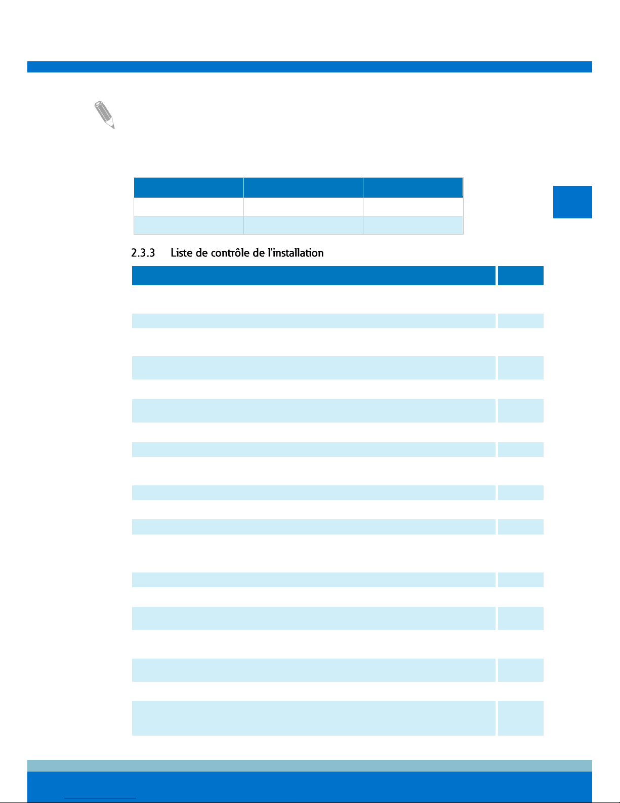
5. Remplissez la liste de contrôle de l'installation.
6. Organisez la venue d'un personnel qualifié pour la mise en service et la vérification du
bon fonctionnement.
23
FR
24
NOTE : La mise en service et la vérification du bon fonctionnement devront être exécutées
par un ingénieur du service clientèle d'Eaton ou par le personnel d'entretien qualifié agréé
par Eaton ; autrement, les conditions générales de la garantie énoncées dans la Garantie
sont annulées.
Avant d'installer le système UPS, il est indispensable de lire et de comprendre comment ce
manuel s'applique au système à installer. Utilisez les procédures et illustrations fournies
pour créer un plan logique d'installation du système.
Afin que le système UPS puisse fonctionner avec une efficience optimale, le site
d'installation doit être conforme aux conditions environnementales exposées dans le Guide
d'utilisation et d'installation de l'UPSD Eaton 93PM 100-500 kVA.
Le cadre d'installation doit être conforme aux exigences de poids et d'encombrement de
l'UPS énoncées aux Tableaux 1 et 2.
Les dimensions de l'armoire d'UPS sont indiquées dans l'illustration 2. Notez que la
dimension de profondeur inclut les presse-étoupe.
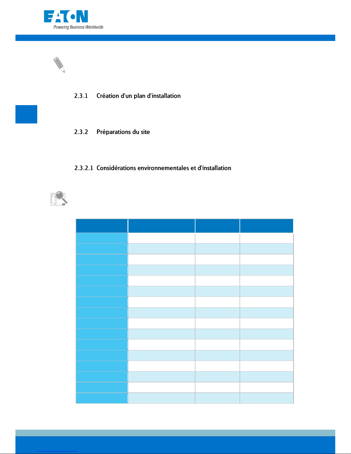
Tableau 1. Poids des armoires UPS avec emballage carton
Modèle d'UPS
Poids pour l'expédition
[kg]
Poids installé
[kg]
Charge au sol
[kg/m2]
93PM-100(400)
720
680
439
93PM-150(400)
785
745
540
93PM-200(400)
850
810
587
93PM-250(400)
915
875
635
93PM-300(400)
980
940
682
93PM-350(400)
1045
1005
729
93PM-400(400)
1110
1070
776
93PM-100(500)
720
680
439
93PM-150(500)
785
745
540
93PM-200(500)
850
810
587
93PM-250(500)
850
810
587
93PM-300(500)
915
875
635
93PM-350(500)
980
940
682
93PM-400(500)
1045
1005
729
93PM-450(500)
1110
1070
776
93PM-500(500)
1110
1070
776
24
FR
25
Les armoires UPS utilisent un apport d'air froid pulsé pour réguler la température des
composants internes. Par défaut, les entrées d'air sont situées à l'avant de l'armoire et les
sorties sont situées à l'arrière - voir illustration 5. Prévoyez un dégagement suffisant
devant et derrière chaque armoire pour une circulation d'air correcte.
À l'aide du kit d'évacuation d'air par le haut en option, il est possible de configurer les
sorties d'air dans la partie arrière supérieure de l'armoire. Cette option permet d'installer
l'UPS contre un mur ou dos à dos. La température de l'air froid qui pénètre dans l'UPS ne
doit pas dépasser la température ambiante maximum spécifiée. Pour des exigences
relatives à la ventilation, consultez le Guide d'utilisation et d'installation de l'UPS Eaton
93PM 100-500 kVA.
Tableau 2. Dégagements minimum autour de l'armoire de l'UPS
Depuis le haut de l'armoire
500 mm
Depuis l'avant de l'armoire
900 mm
Depuis l'arrière de l'armoire
*) 0 mm si le kit d'évacuation d'air par le haut est installé
450 mm*
Depuis le côté de l'armoire
0 mm
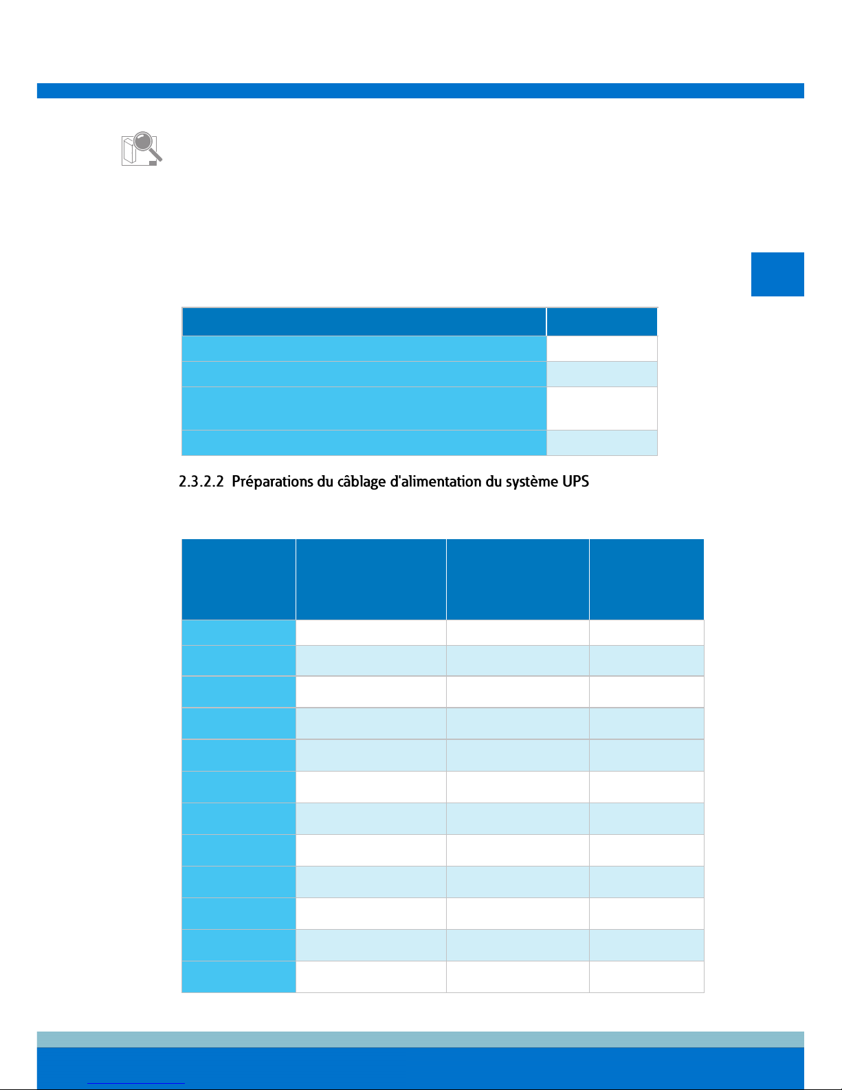
Tableau 3. Tailles minimales recommandées des câbles multiconducteurs et fusibles pour les câbles
d'entrée de redresseur et dérivation et de sortie d'UPS
Modèle d'UPS
Câbles de phase
Fusible d'entrée de
dérivation de
maintenance et de
dérivation statique,
redresseur [A]
Câble PE [mm2]
93PM-100(400)
95 mm2
200
50
93PM-150(400)
185 mm2
315
95
93PM-200(400)
240 mm2
400
120
93PM-250(400)
2 x 120 mm2 par phase
500
120
93PM-300(400)
2 x 185 mm2 par phase
630
185
93PM-350(400)
2 x 240 mm2 par phase
700
240
93PM-400(400)
2 x 240 mm2 par phase
800
240
93PM-100(500)
95 mm2
200
50
93PM-150(500)
185 mm2
315
95
93PM-200(500)
240 mm2
400
120
93PM-250(500)
2 x 120 mm2 par phase
500
120
93PM-300(500)
2 x 120 mm2 par phase
500
120
25

FR
26
Modèle d'UPS
Câbles de phase
Fusible d'entrée de
dérivation de
maintenance et de
dérivation statique,
redresseur [A]
Câble PE [mm2]
93PM-350(500)
2 x 185 mm2 par phase
630
185
93PM-400(500)
2 x 240 mm2 par phase
800
240
93PM-450(500)
2 x 240 mm2 par phase
800
240
93PM-500(500)
2 x 240 mm2 par phase
800
240
ATTENTION
Assurez-vous que le courant de court-circuit prévu résultant sur les bornes d'entrée de
l'UPS est égal ou inférieur à celui de condition déclaré sur la plaque de type de l'UPS.
Tableau 4. Tailles minimales recommandées des câbles multiconducteurs et fusibles pour le banc de
batteries externe
Modèle d'UPS
Câble de batterie, ligne pos. & nég.
Fusible de batterie [A]
93PM-100(400)
185 mm2 par pôle
315
93PM-150(400)
240 mm2 par pôle
400
93PM-200(400)
2 x 185 mm2 par pôle
630
93PM-250(400)
2 x 240 mm2 par pôle
700
93PM-300(400)
2 x 240 mm2 par pôle
800
93PM-350(400)
4 x 120 mm2 par pôle
1000
93PM-400(400)
4 x 185 mm2 par pôle
1250
93PM-100(500)
120 mm2 par pôle
250
93PM-150(500)
240 mm2 par pôle
400
93PM-200(500)
2 x 120 mm2 par pôle
500
93PM-250(500)
2 x 185 mm2 par pôle
630
93PM-300(500)
2 x 240 mm2 par pôle
800
93PM-350(500)
4 x 120 mm2 par pôle
1000
93PM-400(500)
4 x 120 mm2 par pôle
1000
93PM-450(500)
4 x 185 mm2 par pôle
1250
93PM-500(500)
4 x 185 mm2 par pôle
1250
Consulter les réglementations nationales et locales de l'électricité pour les pratiques
acceptables de câblage externes.
Pour en savoir plus sur les courants nominaux et maximum pour les puissances et tension
nominales, consultez le Guide d'utilisation et d'installation de l'UPS Eaton 93PM 100-500 kVA.
Pour en savoir plus sur les bornes de batterie dans le 93PM avec option de batterie séparée,
consultez le Guide d'utilisation et d'installation de l'UPS Eaton 93PM 100-500 kVA.
26
FR
27
NOTE : La protection externe contre les surintensités n'est pas fournie par ce produit mais
elle est exigée par la réglementation. Pour les exigences de câblage, se reporter à
Tableau 3 et au Tableau 4. Si un dispositif de déconnexion verrouillable de sortie est
requis, il doit être fourni par l'utilisateur.
Tableau 5. Couples de bornes de câble d'alimentation d'UPS
Fonction
Couple de serrage [Nm]
Taille du boulon
Phases
80
M12
Neutre et terre
47
M10
Action
Oui/Non
Tous les matériaux d'emballage et accessoires de fixation sont retirés de chaque
armoire.
Chaque armoire du système UPS est placée sur son site d'installation.
Un kit de mise à la terre/montage de l'armoire est installé entre les armoires boulonnées
ensemble.
Tous les câbles et gaines sont correctement acheminés vers l'UPS et les armoires
auxiliaires.
Tous les câbles d'alimentation sont aux bonnes dimensions et raccordés correctement.
Les conducteurs neutres sont raccordés ou liés à la masse conformément aux
exigences.
Un conducteur de terre est correctement installé.
Les câbles de batterie sont raccordés aux connecteurs de batterie.
Un shunt de dérivation et un câblage de signal de contact auxiliaire sont connectés de
l'UPS vers le disjoncteur de batterie.
Des branchements LAN sont installés.
Toutes les connexions LAN sont exécutées.
La climatisation est installée et fonctionne correctement.
La zone autour du système UPS installé est propre et dépoussiérée (Il est recommandé
d'installer le système UPS sur un sol adapté à l'équipement informatique ou
électronique).
Un dégagement adéquat est prévu autour de l'UPS et des autres armoires.
Un éclairage correct est prévu autour de tout l'équipement de l'UPS.
Il existe une prise de courant de service de 230 V CA à 7,5 mètres au plus du site
d'installation de l'UPS.
Le dispositif d'arrêt d'urgence à distance (REPO) est correctement installé et son câblage
est raccordé à l'intérieur de l'armoire de l'UPS.
Si l'EPO est utilisé dans la configuration NF, un cavalier est installé sur l'EPO entre les
broches 1 et 2.
(OPTION) Les relais d'alarme et sorties de signal sont correctement câblés.
(OPTION) Une commande de déconnexion de batterie à distance est montée sur son
site d'installation et son câblage est raccordé à l'intérieur de l'armoire de l'UPS et à
l'armoire de la batterie.
27
FR
28
Action
Oui/Non
(OPTION) Les accessoires sont montés sur leur site d'installation et leurs câblages sont
raccordés à l'intérieur de l'armoire de l'UPS.
La mise en service et la vérification du bon fonctionnement sont réalisées par un
ingénieur agréé du service client d'Eaton ou par l'ingénieur d'entretien qualifié agréé par
Eaton.
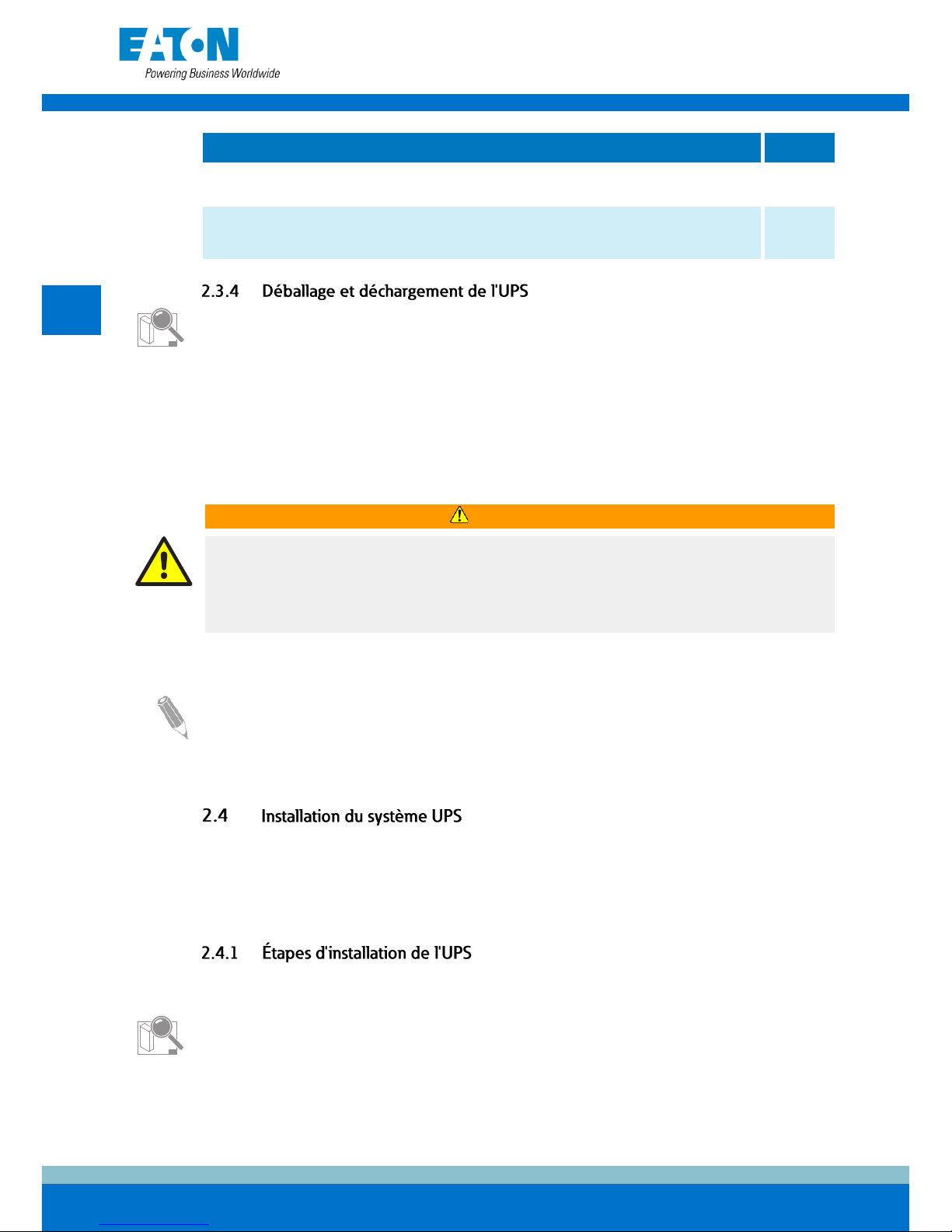
Le déballage et le déchargement de l'UPS sont illustrés en 7.1 – 7.8.
Avant de commencer à déballer et décharger l'UPS, vérifiez l'indicateur TipNTell /
DropNTell sur la surface de l'emballage. Si l'équipement a été correctement transporté en
position verticale, les indicateurs devraient être intacts. Si la flèche de l'indicateur TipNTell
est devenue toute bleue ou si la ou les flèches de l'indicateur DropNTell sont noires,
contactez les parties concernées pour déclarer un transport incorrect.
Pour son transport, l'armoire de l'UPS est boulonnée sur la palette en bois. Avant de la
décharger de la palette, utilisez un chariot élévateur ou tout autre équipement de
manutention pour déplacer l'armoire vers le site d'installation.
AVERTISSEMENT
L'armoire de l'UPS est lourde. Si les instructions de déballage ne sont pas suivies à la
lettre, l'armoire risque de basculer et de provoquer des blessures graves.
N'inclinez pas l'armoire de l'UPS à un angle supérieur à 10 degrés depuis la verticale :
elle pourrait basculer.
NOTE : Une fois les supports d'expédition retirés, écartez immédiatement l'unité de la
palette.
Si l'armoire est déplacée de son emplacement d'installation d'origine vers un nouvel
emplacement sur la palette, fixez les supports d'expédition ou les plaques de couvercle
inférieures sur l'armoire et la palette.
L'opérateur doit fournir le câblage pour la connexion de l'UPS à la source d'alimentation
locale. L'installation de l'UPS doit être confiée à un électricien local qualifié. L'inspection de
l'installation et la mise en service initiale de l'UPS ainsi que l'installation d'une armoire de
batteries supplémentaire doivent être effectuées par un ingénieur agréé du service client
d'Eaton ou par un personnel d'entretien qualifié agréé par Eaton.
Pour installer un 93PM avec option de batterie séparée, consultez le Guide d'utilisation et
d'installation de l'UPS Eaton 93PM 100-500 kVA.
Le câblage d'excitation de batterie X6 est indiqué en illustration 8.
1
Bobine d'excitation de shunt (+24 V C1)
2
Retour de bobine d'excitation de shunt (TRIP C2)
3
Sans usage
4
Signal d'état (DET 3.14)
5
Retour de signal d'état (GND 3.13)
28
 Loading...