

Eaton 93PM-250(400), 93PM-100(400), 93PM-300(400), 93PM-350(400), 93PM-400(400) User And Installation Manual
...
User's and installation
guide
Eaton 93PM UPS 30–200 kVA
P-164000249

Copyright © 2017 Eaton Corporation plc. All rights reserved.
This manual contains important instructions that you should follow during installation and
maintenance of the UPS and batteries. Please read all instructions before operating the
equipment and save this manual for future reference.
This is a product for commercial and industrial application in the second environment.
Installation restrictions or additional measures may be needed to prevent disturbances.
The contents of this manual are the copyright of the publisher and may not be reproduced
(even extracts) without the written approval of Eaton Corporation. Every care has been
taken to ensure the accuracy of the information contained in this manual, but no liability
can be accepted for any errors or omission. The right to make design modifications is
reserved.
Unauthorized copying and lending are prohibited.
Eaton Power Quality Oy
Address:
Koskelontie 13
FI-02920 Espoo
FINLAND
Internet: www.eaton.eu
Original instructions _X_ / Translation of the original instructions __
Eaton 93PM UPS 30–200 kVA User's and installation guide
©
Eaton Corporation plc 2017. All rights reserved. Revision: 005 Document ID: P-164000249 2 (126)

Contents
1 How to read this manual.......................................................................... 7
1.1 Safety-related signs.................................................................... 7
1.2 Safety symbols............................................................................7
1.2.1 Hazard symbols............................................................. 7
1.2.2 Prohibited action symbols..............................................7
1.2.3 Mandatory action symbols............................................. 8
1.3 Conventions used in this document............................................ 8
1.4 Glossary......................................................................................8
2 Safety instructions..................................................................................10
2.1 Audience................................................................................... 12
2.2 CE marking............................................................................... 12
2.3 User precautions.......................................................................12
2.4 Environment..............................................................................13
2.5 Symbols on the UPS and accessories......................................13
2.6 For more information.................................................................14
3 Introduction to Eaton UPS......................................................................15
3.1 Looking inside the UPS system................................................ 16
3.2 UPS operating modes...............................................................18
3.2.1 Normal operating modes............................................. 19
3.2.2 Stored energy and battery mode................................. 23
3.2.3 Bypass mode............................................................... 25
3.3 UPS features.............................................................................27
3.3.1 Advanced Battery Management.................................. 27
3.3.2 Powerware Hot Sync................................................... 27
3.3.3 Power Conditioner....................................................... 28
3.3.4 Frequency Converter................................................... 28
3.3.5 Sync Control................................................................ 28
3.4 Software and connectivity features........................................... 29
3.4.1 User interface.............................................................. 29
3.4.2 Power Management Software..................................... 29
3.5 Options and accessories...........................................................29
3.5.1 Maintenance Bypass Switch........................................29
3.5.2 93PM 200 kW SIAC-MBS............................................30
3.5.3 Top air exhaust kit....................................................... 30
3.5.4 Top cable access kit.................................................... 30
3.5.5 Single feed kit.............................................................. 30
3.5.6 Separate battery option............................................... 30
3.5.7 Field Installed UPM......................................................30
3.6 Battery system.......................................................................... 31
Eaton 93PM UPS 30–200 kVA
User's and installation guide
©
Eaton Corporation plc 2017. All rights reserved. Revision: 005 Document ID: P-164000249 3 (126)

3.6.1 UPS Battery Switchgear.............................................. 31
3.7 Basic system configurations..................................................... 32
4 UPS installation plan and unpacking......................................................35
4.1 Creating an installation plan......................................................35
4.2 Installation checklist.................................................................. 36
4.3 Site preparations.......................................................................36
4.3.1 Environmental and installation considerations.............37
4.3.2 UPS system power wiring preparations.......................41
4.4 Unpacking and unloading the UPS........................................... 46
5 UPS system installation......................................................................... 50
5.1 Installing the UPS 30-50 kW, 80-150 kW and 160-200 kW
frames..............................................................................................50
5.2 Connector and power cable terminal locations......................... 55
5.3 Installing 93PM 160-200kW with side integrated accessory
cabinet MBS.................................................................................... 58
5.4 Installing the battery system..................................................... 62
5.4.1 Installing the battery system for 93PM UPS with
separate battery option.......................................................64
5.4.2 Battery trip wiring......................................................... 65
5.5 Installing a remote EPO switch ................................................ 69
5.6 Installing interface connections.................................................70
5.6.1 Installing customer input signals interface................... 71
5.6.2 Battery breaker wiring interface................................... 71
5.6.3 Relay output interface connections..............................71
5.6.4 Industrial Relay Card interface connections................ 71
5.6.5 MiniSlot interface connections..................................... 72
5.6.6 Installing signal interface connections in a parallel
system................................................................................ 73
5.7 Wiring parallel 93PM UPS systems.......................................... 73
5.7.1 Power wiring overview................................................. 73
5.7.2 Control signals overview..............................................75
5.7.3 Installing bypass control wiring.................................... 76
5.8 UPS system interface wiring preparation..................................79
6 Communication interfaces......................................................................80
6.1 MiniSlot cards........................................................................... 80
6.2 Intelligent Power Software........................................................ 82
6.3 Signal input monitoring............................................................. 83
6.4 General purpose relay contact..................................................83
6.5 Configuring relays..................................................................... 84
Eaton 93PM UPS 30–200 kVA
User's and installation guide
©
Eaton Corporation plc 2017. All rights reserved. Revision: 005 Document ID: P-164000249 4 (126)

7 UPS operating instructions.....................................................................88
7.1 UPS controls and indicators......................................................88
7.1.1 Control panel............................................................... 88
7.1.2 Status indicators.......................................................... 89
7.1.3 System events............................................................. 91
7.1.4 Menu structure of the 93PM UPS................................ 91
7.2 Signing in.................................................................................. 95
7.3 System control instructions....................................................... 96
7.3.1 Starting the UPS system in the double conversion
mode...................................................................................96
7.3.2 Starting the UPS system in the bypass mode............. 97
7.3.3 Transferring from the double conversion mode to
the bypass mode................................................................ 97
7.3.4 Transferring from the bypass mode to the double
conversion mode................................................................ 98
7.3.5 Transferring from the double conversion mode to
the Energy Saver System mode.........................................98
7.3.6 Transferring from the Energy Saver System mode
to the double conversion mode.......................................... 98
7.3.7 Shutting down the UPS system and critical load......... 99
7.3.8 De-energizing the critical load..................................... 99
7.4 UPS control instructions..........................................................100
7.4.1 Starting a single UPS.................................................100
7.4.2 Shutting down a single UPS...................................... 101
7.4.3 Enabling and disabling the battery charger............... 101
7.5 UPM control instructions......................................................... 101
7.5.1 Starting the UPMs......................................................101
7.5.2 Shutting down the UPMs........................................... 102
7.6 Using the Remote Emergency Power-off switch.....................102
7.7 Turning the UPS from the double conversion mode to the
maintenance bypass mode............................................................103
7.8 Turning the UPS from the maintenance bypass mode to
the double conversion mode..........................................................105
8 UPS maintenance................................................................................ 107
8.1 Important safety instructions................................................... 107
8.2 Preventive maintenance......................................................... 108
8.2.1 Daily maintenance..................................................... 108
8.2.2 Monthly maintenance.................................................108
8.2.3 Periodic maintenance................................................ 109
8.2.4 Annual maintenance.................................................. 109
8.2.5 Battery maintenance..................................................109
8.3 Recycling the used UPS or batteries...................................... 109
8.4 Maintenance training...............................................................110
Eaton 93PM UPS 30–200 kVA
User's and installation guide
©
Eaton Corporation plc 2017. All rights reserved. Revision: 005 Document ID: P-164000249 5 (126)

9 Technical data......................................................................................111
9.1 Directives and standards........................................................ 111
9.2 UPS system input................................................................... 112
9.3 UPS system output................................................................. 112
9.4 UPS environmental specifications.......................................... 113
9.5 Battery specification................................................................114
10 Warranty...............................................................................................115
10.1 General................................................................................... 115
10.2 Whom to contact in case of Warranty..................................... 116
Appendix A: Relay Alarms.............................................................................117
Eaton 93PM UPS 30–200 kVA User's and installation guide
©
Eaton Corporation plc 2017. All rights reserved. Revision: 005 Document ID: P-164000249 6 (126)
1 How to read this manual
1.1 Safety-related signs
The following table explains the safety-related signs used in this document.
DANGER
DANGER indicates a hazard with a high level of risk which, if
not avoided, will result in serious injury or death.
WARNING
WARNING indicates a hazard with a medium level of risk which,
if not avoided, could result in serious injury or death, or damage
to your machine.
CAUTION
CAUTION indicates a hazard with a low level of risk which, if not
avoided, could result in minor or moderate injury, or damage to
your machine.
Note: Notes are used to indicate important information and useful tips.
1.2 Safety symbols
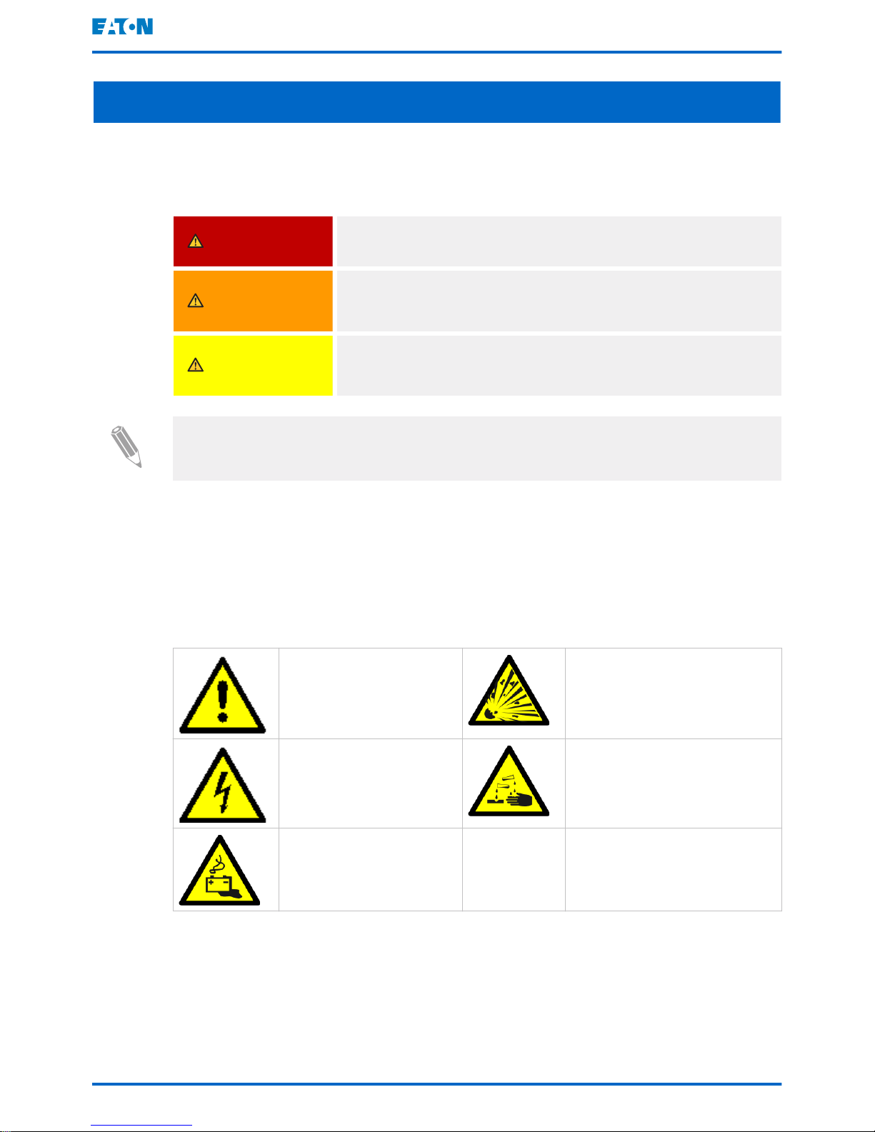
1.2.1 Hazard symbols
These symbols indicate a hazardous situation or action. Symbols are used to
warn of situations, which may cause environmental damage and personal injury.
General warning sign Explosion and fire hazard
Electrical hazard Corrosive hazard
Battery hazard
1.2.2 Prohibited action symbols
These symbols are used to indicate an action that should not be taken.
Eaton 93PM UPS 30–200 kVA
User's and installation guide
©
Eaton Corporation plc 2017. All rights reserved. Revision: 005 Document ID: P-164000249 7 (126)
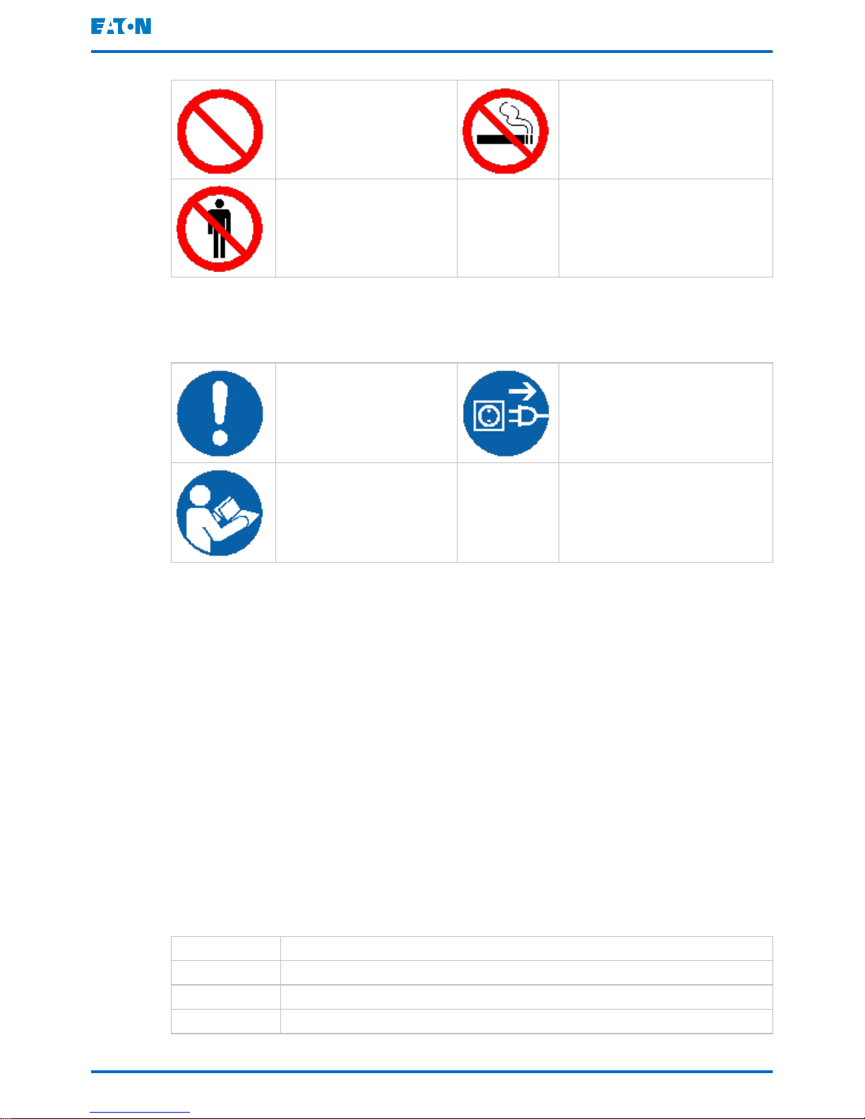
General symbol for prohibited action
No smoking
Limited or restricted access
1.2.3 Mandatory action symbols
These symbols are used to indicate an action that must be taken.
General symbol for mandatory action
Disconnect from power
source
Read the manual or instructions
1.3 Conventions used in this document
This document uses the following type conventions:
• Bold type highlights important concepts in discussions, key terms in
procedures and menu options, or represents a command or option that you
type or enter at a prompt.
•
Italic type
highlights notes and new terms when they are defined.
• Screen type represents information that appears on the screen or LCD.
1.4 Glossary
Eaton documentation uses the following acronyms to refer to Eaton UPS
products or their parts:
Table 1: Glossary of acronyms
ABM Advanced Battery Management
BIB Bypass Input Breaker
EAA Energy Advanced Architecture
EBC External Battery Cabinet
Eaton 93PM UPS 30–200 kVA User's and installation guide
©
Eaton Corporation plc 2017. All rights reserved. Revision: 005 Document ID: P-164000249 8 (126)

EPO Emergency Power-off
ESS Energy Saver System
F-UPM Field Installed UPM
IPM Intelligent Power Manager
IPP Intelligent Power Protector
MBP Maintenance Bypass
MBS Maintenance Bypass Switch
MCB Miniature Circuit Breaker
MIS Maintenance Isolation Switch
MOB Module Output Breaker
REPO Remote Emergency Power-off
RIB Rectifier Input Breaker
SCR Silicon-controlled Rectifier
STSW Static Switch
UPM Uninterruptible Power Module
UPS Uninterruptible Power Supply
VMMS Variable Module Management System
Eaton 93PM UPS 30–200 kVA User's and installation guide
©
Eaton Corporation plc 2017. All rights reserved. Revision: 005 Document ID: P-164000249 9 (126)
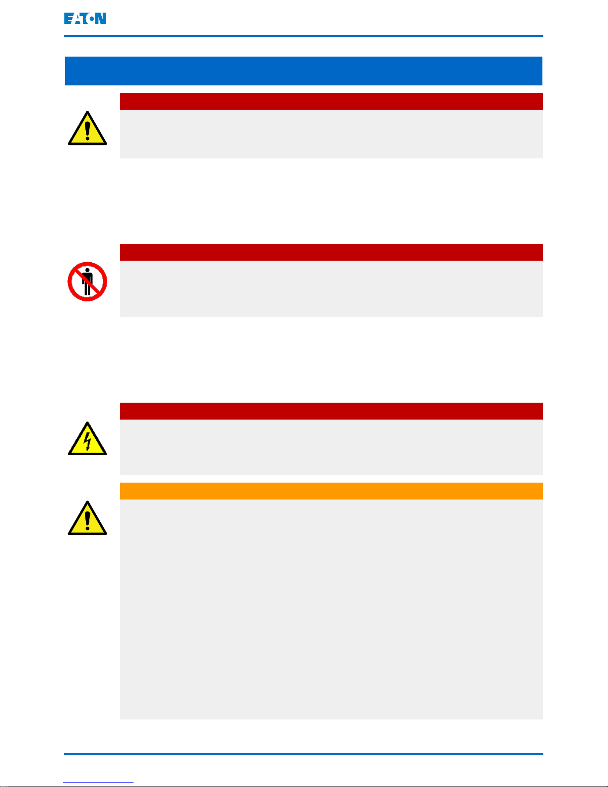
2 Safety instructions
DANGER
Important safety instructions!
Keep these instructions!
This document contains important instructions that must be obeyed during the
installation, operation and maintenance of the UPS and the batteries. Read all
instructions before operating the equipment. Keep this manual for future
reference. These instructions are also available for download at www.eaton.eu/
93pm.
DANGER
Operations inside the UPS must be done by an authorized Eaton Customer
Service Engineer or by other qualified service personnel authorized by Eaton.
There are no user-serviceable parts in the UPS.
The UPS operates with mains, battery or bypass power. It contains components
that carry high currents and voltage. A properly installed enclosure is earthed
and IP20 rated against electric shock and unwanted objects. The UPS is a
sophisticated power system and only qualified personnel can install and service
it.
DANGER
This UPS carries lethal voltages. All repairs and service must be done by
authorized personnel only. There are no user-serviceable parts inside the
UPS.
WARNING
The UPS is powered by its own energy source (batteries). The output
terminals could be energized even when the UPS is disconnected from an AC
source. To reduce the risk of fire or electric shock, install the UPS in a
temperature and humidity controlled, indoor environment that is free of
conductive contaminants. See temperature and humidity limits in Chapter 9.
The ambient temperature limit must not be exceeded. Do not operate the
UPS near water or excessive humidity. The system is not intended for
outdoor use.
Before you start any installation or service work, make sure that all AC and
DC power sources are disconnected. Power can come from multiple sources.
Also ensure system grounding / PE continuity.
In a parallel system, the output terminals could be energized even when the
UPS is turned off.
Eaton 93PM UPS 30–200 kVA User's and installation guide
©
Eaton Corporation plc 2017. All rights reserved. Revision: 005 Document ID: P-164000249 10 (126)
WARNING
Batteries present a risk of electric shock or burn from high short-circuit
current. Observe proper precautions.
Electric energy hazard. Do not attempt to alter any battery wiring or
connectors. Attempting to alter wiring can cause injury.
Do not open or mutilate batteries. Released electrolyte can be toxic and is
harmful to the skin and eyes.
Batteries can contain HIGH VOLTAGES, and CORROSIVE, TOXIC and
EXPLOSIVE substances. Because of the battery string the output terminals
can carry high voltage even when the AC supply is not connected to the UPS.
Read the shutdown instructions carefully.
IMPORTANT: The battery may consist of multiple parallel strings. Make sure
that you disconnect all strings before installation.
CAUTION
Only qualified service personnel knowledgeable of batteries and the required
precautions can do the installation or service work on batteries. Keep
unauthorized personnel away from the batteries. Before you install or replace
batteries, consider all the warnings, cautions, and notes concerning
appropriate handling. Do not disconnect the batteries when the UPS is in the
Battery mode.
Make sure that your replacement batteries are of the same number and type
as the battery that was originally installed in the UPS. See more accurate
instructions on the UPS.
Before you connect or disconnect battery terminals, disconnect the charging
source by opening the corresponding battery circuit breaker.
If the battery is inadvertently grounded, remove the source of the ground.
Contacting any part of a grounded battery can cause a risk of electric shock.
If you disconnect the grounding connection before you work on the batteries,
the risk of an electric shock is less likely.
Dispose of batteries according to your local disposal requirements. Do not
dispose of batteries in a fire. When exposed to flame, batteries may explode.
To ensure proper cooling airflow and to protect personnel from dangerous
voltages inside the unit, keep the UPS door closed and the front panels
installed.
Do not install or operate the UPS system close to gas or electric heat
sources. Keep the operating environment within the parameters stated in this
document.
Eaton 93PM UPS 30–200 kVA
User's and installation guide
©
Eaton Corporation plc 2017. All rights reserved. Revision: 005 Document ID: P-164000249 11 (126)
CAUTION
Keep the surroundings of the UPS uncluttered, clean, and free from excess
moisture.
Obey all DANGER, CAUTION, and WARNING notices on the equipment.
2.1 Audience
This document is intended for:
• People who plan and perform the installation of the UPS
• People who use the UPS
This document provides guidelines for how to examine the UPS delivery and
how install and operate the UPS.
The reader is expected to know the fundamentals of electricity, wiring, electrical
components and electrical schematic symbols. This document is written for a
global reader.
CAUTION
Read this document before you start to operate or perform work on the UPS.
2.2 CE marking
The product has a CE marking in compliance with the following European
directives:
• LV Directive (Safety) 2014/35/EU
• EMC Directive 2014/30/EU
Declarations of conformity with UPS harmonized standards and directives EN
62040-1 (Safety) and EN 62040-2 (EMC) are available at
www.eaton.eu
or by
contacting your nearest Eaton office or authorized partner.
2.3 User precautions
The only permitted user operations.
• Startup and shutdown of the UPS, excluding the commissioning startup.
• Use of the LCD control panel and the Maintenance Bypass Switch (MBS).
• Use of optional connectivity modules and their software.
Obey the precautions and only perform the described operations. Any deviation
from the instructions can be dangerous to the user or cause accidental load
loss.
Eaton 93PM UPS 30–200 kVA
User's and installation guide
©
Eaton Corporation plc 2017. All rights reserved. Revision: 005 Document ID: P-164000249 12 (126)
DANGER
Do not open any other screws in the unit than those holding the cover plates
of the MiniSlots and the MBS locking plate. Failure to recognize the electrical
hazards can prove fatal.
CAUTION
The 30–50 kW models are available as a C2 category UPS as an option,
which can be placed both in residential and commercial or industrial
environments. When included in a residential environment, this product may
cause radio interference. in which case you may have to take preventive
measures.
By standard, this is a C3 category product for commercial and industrial
application in the second environment. Installation restrictions or
measurements may be needed to prevent disturbances.
2.4 Environment
The UPS must be installed according to the recommendations in this document.
Never install the UPS in an airtight room, in the presence of flammable gases, or
in an environment exceeding the specifications.
Excessive amount of dust in the operating environment of the UPS may cause
damage or lead to malfunction. Always protect the UPS from the outside
weather and sunshine.
WARNING
During charge, float charge, heavy discharge, and overcharge, hydrogen and
oxygen gases are emitted from lead-acid and NiCd batteries into the
surrounding atmosphere. Explosive gas mixture may be created if the
hydrogen concentration exceeds 4% by volume in air. Ensure the necessary
air flow rate for the ventilation of the UPS location.
2.5 Symbols on the UPS and accessories
The following are examples of symbols used on the UPS or its accessories. The
symbols are used to alert you of important information.
RISK OF ELECTRIC SHOCK
Indicates that a risk of electric shock is present and the associated
warning should be observed.
Eaton 93PM UPS 30–200 kVA User's and installation guide
©
Eaton Corporation plc 2017. All rights reserved. Revision: 005 Document ID: P-164000249 13 (126)
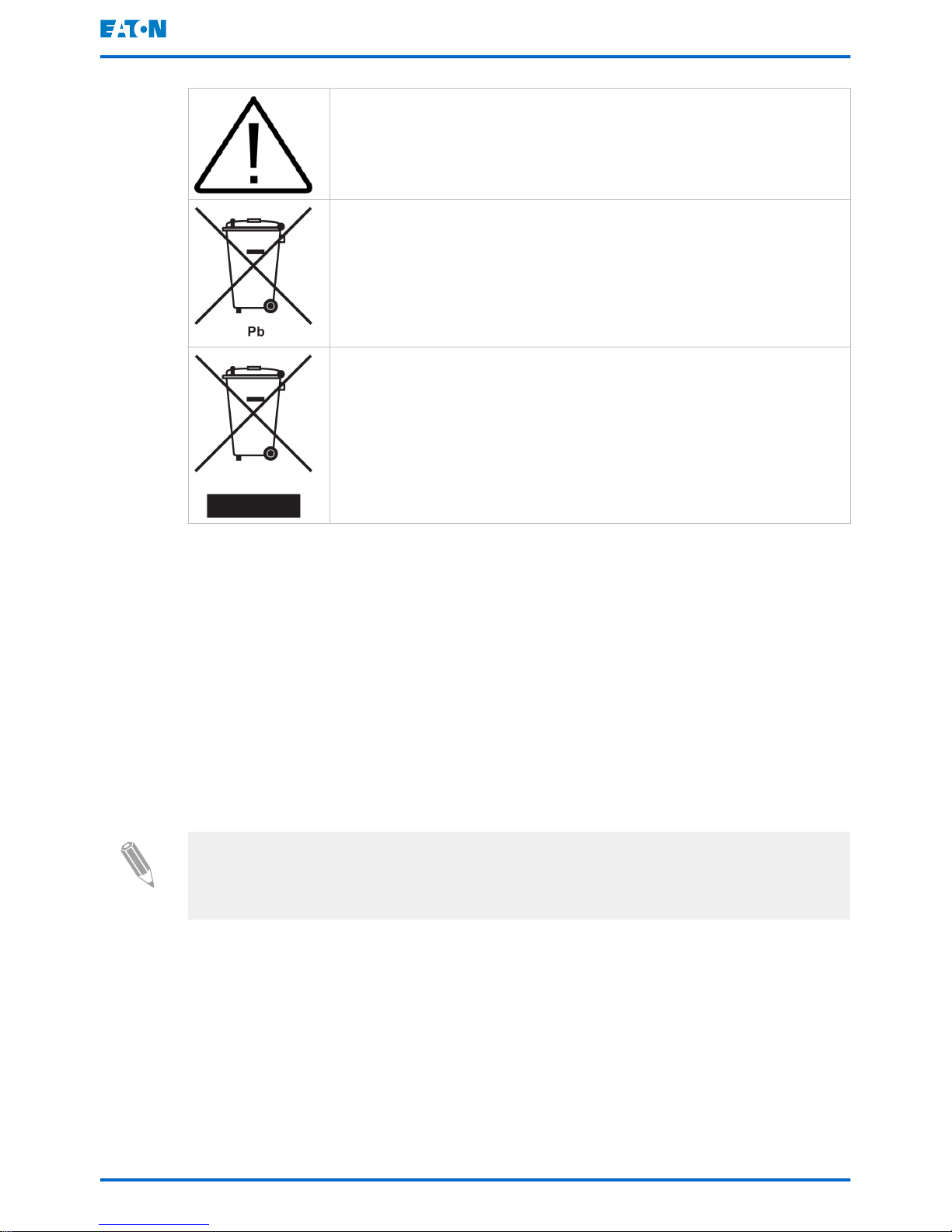
CAUTION: REFER TO OPERATOR'S MANUAL
Refer to your operator's manual for additional information, such as
important operating and maintenance instructions.
This symbol indicates that you may not discard the UPS or the UPS
batteries in the trash. This product involves sealed, lead-acid batteries and they must be disposed of properly. For more information,
contact your local recycling / reuse or hazardous waste center.
This symbol indicates that you may not discard waste electrical or
electronic equipment (WEEE) in the trash. For proper disposal, contact your local recycling / reuse or hazardous waste center.
2.6 For more information
Address any inquiries about the UPS and the battery cabinet to the local office
or an agent authorized by the manufacturer. Quote the type code and the serial
number of the equipment.
Call your local service representative if you need help with any of the following:
• scheduling initial startup
• regional locations and telephone numbers
• a question about any of the information in this manual
• a question that this manual does not answer
Note: For more information about the installation space, safe operation and
working, see IEC 62485-2: Safety requirements for secondary batteries and
battery installations.
Eaton 93PM UPS 30–200 kVA User's and installation guide
©
Eaton Corporation plc 2017. All rights reserved. Revision: 005 Document ID: P-164000249 14 (126)
3 Introduction to Eaton UPS
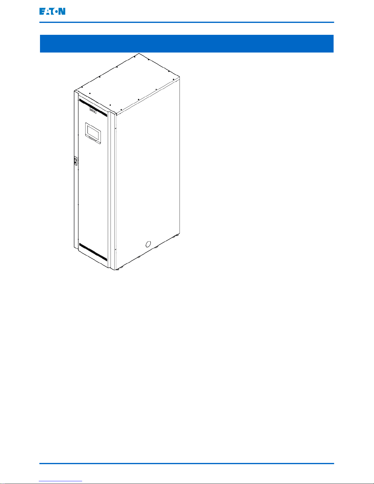
Figure 1. Eaton 93PM UPS
The Eaton® 93PM uninterruptible power supply (UPS) is a true online,
continuous-duty, transformerless, double-conversion, solid-state, three-phase
system that supplies conditioned and uninterruptible AC power to critical load
and protects it from power failures.
The UPS is used to prevent loss of valuable electronic information, minimize
equipment downtime, and minimize the adverse effect on production equipment
due to unexpected power problems.
The Eaton UPS continually monitors incoming electrical power and removes the
surges, spikes, sags, and other irregularities that are inherent in commercial
utility power. Working with a building’s electrical system, the UPS system
supplies clean, consistent power that sensitive electronic equipment require for
reliable operation. During brownouts, blackouts, and other power interruptions,
batteries provide emergency power to safeguard operation.
The UPS system is housed in a single, free-standing cabinet with safety shields
behind the door for protection against hazardous voltage. Each UPS cabinet has
Eaton 93PM UPS 30–200 kVA
User's and installation guide
©
Eaton Corporation plc 2017. All rights reserved. Revision: 005 Document ID: P-164000249 15 (126)

a centralized system static bypass. The available static bypass ratings are 50
kW, 60 kVA, 100 kW, 150 kW and 200 kW. The static bypass size is chosen
according to UPS system power.
Eaton 93PM output power ratings are based on 50 kW rated uninterruptible
power modules (UPMs). A single UPS cabinet can house one to four UPMs to
get ratings of:
• 1 x 50 kW = 50 kW (or 60 kVA, PF 0.9)
• 2 x 50 kW = 100 kW
• 3 x 50 kW = 150 kW
• 4 x 50 kW = 200 kW
See Section
3.7
for a full list of available configurations.
A UPM includes a rectifier, inverter, battery converter, and independent controls.
Each UPM is able to operate independently from the other power modules.
Note: Startup and operational checks must be performed by an authorized
Eaton Customer Service Engineer or by other qualified service personnel
authorized by Eaton, or the terms specified in the Warranty (see Chapter
10
)
become void. This service is offered as part of the sales contract for the UPS.
Contact service in advance (usually a two-week notice is necessary) to
reserve a preferred start-up date.
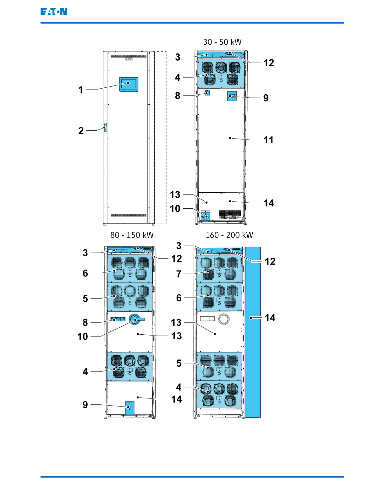
3.1 Looking inside the UPS system
The system level static bypass in the Eaton 93PM UPS cabinet determines the
attainable output power of the UPS. The static bypass line consists of static
switch, a back feed protection isolation device and fuses designed to protect the
static switch. The back feed protection and bypass fuses are located in series
with the static switch. In addition, there is a system level control unit that
constantly monitors the power delivered through the bypass line or to the input
of the UPS. Transfers to static bypass are seamless and performed
automatically by the system as needed, for example, in case of an extended
system overload.
Each UPM includes a rectifier, battery converter, inverter and independent
controls. Each UPM is able to operate and share the load independently,
despite the status of the other UPMs.
If utility power is interrupted or falls outside the parameters specified in Chapter
9
, the UPS uses a backup battery supply to maintain power to the critical load
for a specified period of time or until the utility power returns. For extended
power outages, the UPS allows you to either transfer to an alternative power
system (such as a generator) or shut down your critical load in an orderly
manner.
Eaton 93PM UPS 30–200 kVA
User's and installation guide
©
Eaton Corporation plc 2017. All rights reserved. Revision: 005 Document ID: P-164000249 16 (126)
Eaton 93PM UPS 30–200 kVA User's and installation guide
©
Eaton Corporation plc 2017. All rights reserved. Revision: 005 Document ID: P-164000249 17 (126)

1 Control panel 8 Rectifier input switch (optional)
2 Door latch 9 Battery breaker (optional)
3 Communications area 10 MBS (optional)
4 UPM 1 11 Area for internal batteries
5 UPM 2 12 Communication cable conduit
6 UPM 3 13 Static bypass section
7 UPM 4 14 Power cable connections
3.2 UPS operating modes
The UPS operating modes are as follows:
Operating mode Description
Normal operating modes:
- Double conversion mode Critical load is supplied by the inverter,
which derives its power from rectified utility
AC power. In this mode, the battery charger also provides charging current for the
battery, if needed.
- Variable Module Management System
(VMMS) mode
Critical load is supplied by the inverter. The
inverter derives its power from rectified utility AC power, identically to double conversion mode. In the VMMS mode, the 93PM
UPS system is able to optimise the load
level per power module: the operating efficiency is significantly improved when operating load is below 50% of UPS capacity.
The UPS system will automatically place
the redundant power modules to suspended mode. In case of any anomalies in utility or a sudden load increase, the suspended power modules are able to transfer to
online mode with less than 2 ms transition
time.
- Energy Saver System (ESS) mode Critical load is supported securely by utility
power through the static bypass switch with
double conversion available on-demand
with typically less than a 2 ms transition
time, should any abnormal condition be detected in the utility. When operating in the
ESS mode, the load is protected with inherent surge suppression. Operating the UPS
in the ESS mode increases system efficiency up to 99%, allowing significant savings in energy losses without compromising system reliability
Eaton 93PM UPS 30–200 kVA User's and installation guide
©
Eaton Corporation plc 2017. All rights reserved. Revision: 005 Document ID: P-164000249 18 (126)

Operating mode Description
Stored energy mode Energy is drawn from a DC backup power
source and converted to AC power by the
UPS inverter. Most commonly VRLA batteries are introduced to the system for this
purpose, and the mode of operation is
called the battery mode
Bypass mode Critical load is supported directly by utility
power through the UPS static switch.
3.2.1 Normal operating modes
During normal UPS operation, power for the system is derived from a utility input
source. Unit Online is displayed on the front panel, indicating that the
incoming power is within voltage and frequency acceptance windows.
3.2.1.1 Double conversion mode
Figure 2 shows the path of electrical power through the UPS system when the
UPS is operating in the double conversion mode.
Eaton 93PM UPS 30–200 kVA User's and installation guide
©
Eaton Corporation plc 2017. All rights reserved. Revision: 005 Document ID: P-164000249 19 (126)
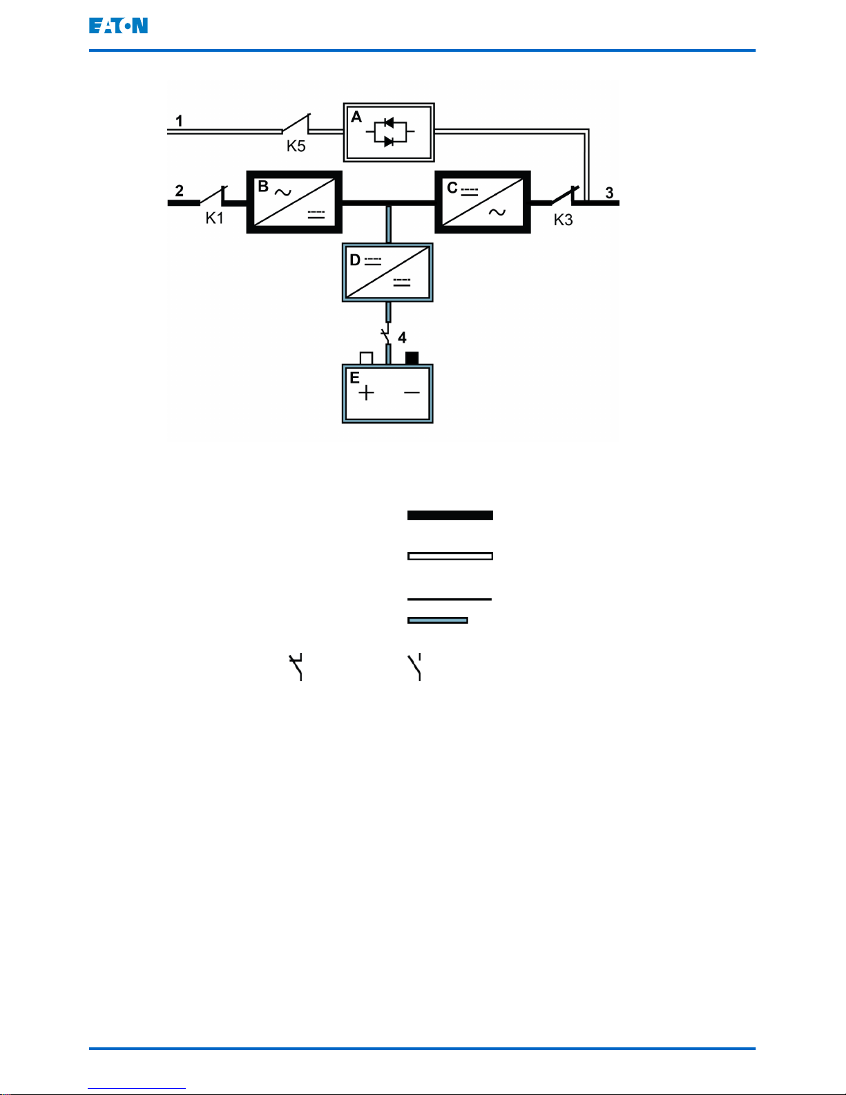
Figure 2. Path of current through the UPS in the double conversion mode
A Static
switch
1 Bypass in-
put
Main power flow
B Rectifier 2 Rectifier in-
put
Energized
C Inverter 3 Output De-energized
D Battery con-
verter
4 Battery
breaker
Trickle current
E Battery Closed Open
Three-phase AC input power is converted to DC using a multilevel converter
with IGBT devices to produce a regulated DC voltage to the inverter. The UPS
status indicated on the display is Unit Online and the UPM status is Active.
The battery converter derives its input from the regulated DC output of the
rectifier and provides regulated charge current to the battery. The battery is
always connected to the UPS and ready to support the inverter should the utility
input become unavailable.
The inverter produces a three-phase AC output to the critical load. The inverter
uses multilevel converter technology with IGBT devices and pulse-width
modulation (PWM) to produce a regulated and filtered AC output.
If the utility AC power is interrupted or is out of specification, the UPS
automatically switches to the battery mode to support the critical load without
interruption. When utility power returns, the UPS returns automatically to the
double conversion mode.
Eaton 93PM UPS 30–200 kVA
User's and installation guide
©
Eaton Corporation plc 2017. All rights reserved. Revision: 005 Document ID: P-164000249 20 (126)

If the UPS becomes overloaded or unavailable, the UPS seamlessly switches to
the bypass mode and continues supplying the load through the static bypass.
The UPS automatically returns to the double conversion mode when the
abnormal condition, such as an extended time overload, is cleared and the
system operation is restored within the specified limits.
If a UPM within the UPS suffers an internal failure, the remaining UPMs
continue to support the load in the double conversion mode. The UPS is
automatically internally redundant when the UPS is not operating at full load.
However, if internal redundancy between the UPMs is not possible due to high
load, the UPS switches automatically to the bypass mode and remains in that
mode until the failure is corrected and the UPS is back in operation.
In an external parallel redundant system, each UPS can be isolated from the
system for service while the remaining UPSs support the load in the double
conversion mode.
3.2.1.2 Variable Module Management System mode
When Variable Module Management System (VMMS) mode is enabled, the load
is powered by UPMs in double conversion mode (see Figure
2
). The UPS
status indicated on the display is Unit Online VMMS and the UPM status is
Active.
UPS efficiency varies according to the load level at which the UPS operates.
VMMS technology enables achieving optimised system efficiency by
automatically optimising the UPM load level. As an example, when the load is
very low, a minimum of one UPM is online. This enhances the UPS system
efficiency by several percentage points.
The remaining UPMs are ready to switch to double conversion mode
instantaneously, if the load increases. The load will remain protected by double
conversion UPS the entire time, even during and after a load step.
It is possible to configure VMMS mode to include power module redundancy at
all times, so that a number of additional redundant UPMs are always online.
When the UPMs are in ready state, the IGBT converters are constantly
powered, since the rectifier input and inverter output contactors are closed. The
DC link is also powered. Only the IGBT gate signals are suspended. The only
step needed to come out of ready state is to gate the IGBT switches. Since DC
voltage is constantly present, the inverter is able to start instantaneously: the 2
ms transfer to double conversion is practically seamless.
3.2.1.3 Energy Saver System mode
Figure
3
shows the path of electrical power through the UPS system when the
UPS is operating in the Energy Saver System (ESS) mode.
Eaton 93PM UPS 30–200 kVA
User's and installation guide
©
Eaton Corporation plc 2017. All rights reserved. Revision: 005 Document ID: P-164000249 21 (126)
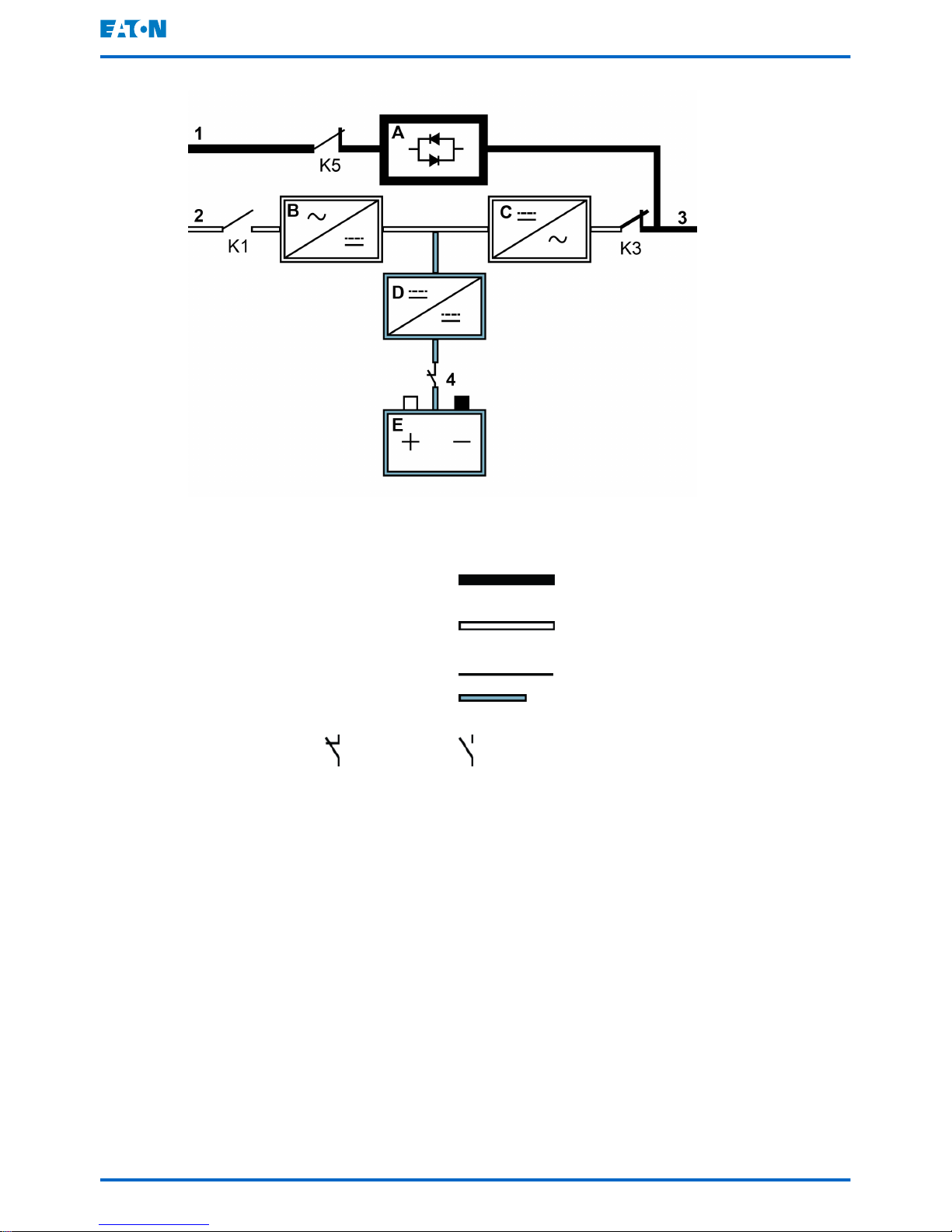
Figure 3. Path of current through the UPS in the Energy saver System mode
A Static
switch
1 Bypass in-
put
Main power flow
B Rectifier 2 Rectifier in-
put
Energized
C Inverter 3 Output De-energized
D Battery con-
verter
4 Battery
breaker
Trickle current
E Battery Closed Open
In the ESS mode, the UPS safely provides mains current directly to the load
when the input is within the acceptable limits by its voltage and frequency. The
UPS status indicated on the display is Unit Online ESS, and the UPM status
is Active. Surge protection and some filtering is also provided, making sure
that clean power is delivered to the load equipment. In case any disturbances
are detected in the incoming power, the UPS switches to the double conversion
mode and continues to supply the critical load through its inverter. In case of a
complete utility outage or if the input power is outside the tolerances of the
system, the UPS transfers to the battery mode and continues to supply
conditioned, clean power to the critical load.
When operating in the ESS mode, the UPS's superior detection and control
algorithms continuously monitor the incoming power quality and allow fast
engagement of the power converters. Typical transition time to the double
conversion mode is less than 2 milliseconds, which is practically seamless.
Eaton 93PM UPS 30–200 kVA
User's and installation guide
©
Eaton Corporation plc 2017. All rights reserved. Revision: 005 Document ID: P-164000249 22 (126)

When the power conditions are within acceptable limits, the UPS operates as a
high efficiency, energy-saving system, providing surge protection for IT
equipment and making sure that clean power is delivered to the facility. The
energy saver system increases system efficiency up to 99% when supplying 20–
100% of nominal load, reducing energy losses by up to 80%.
3.2.2 Stored energy and battery mode
When running normally in the double conversion or ESS mode, the UPS
automatically transfers to supply the load from batteries or some other stored
energy source if a utility power outage occurs, or if the utility power does not
conform to the specified parameters. The UPS status indicated on the display is
On Battery, and the UPM status is Active. In the battery mode, the battery
provides emergency DC power, which is converted to regulated output power by
the inverter.
Figure
4
shows the path of electrical power through the UPS system when
operating in the battery mode.
Eaton 93PM UPS 30–200 kVA User's and installation guide
©
Eaton Corporation plc 2017. All rights reserved. Revision: 005 Document ID: P-164000249 23 (126)

Figure 4. Path of current through the UPS in the battery mode
A Static
switch
1 Bypass in-
put
Main power flow
B Rectifier 2 Rectifier in-
put
Energized
C Inverter 3 Output De-energized
D Battery con-
verter
4 Battery
breaker
Trickle current
E Battery Closed Open
During a utility power failure, the rectifier no longer has an AC utility source from
which to supply the DC output current required to support the inverter. The input
relay K1 opens and the UPS output is powered from the batteries through the
inverter. As the inverter operates uninterrupted through the transition, the load
remains supported continuously without disturbance. If the UPS static bypass is
supplied from the same source as the UPS rectifier, the backfeed protection
contactor K5 also opens. The opening of K1 and K5 prevent system voltages
from bleeding backwards and re-entering the input source through the static
switch or rectifier.
If the input power fails to return or is not within the acceptance windows required
for normal operation, the battery continues discharging until a DC voltage level
is reached where the inverter output can no longer support the connected loads.
When this event occurs, the UPS issues a set of audible and visual alarms
indicating that the batteries have a minimal capacity left and a system shutdown
is imminent. Unless utility power is restored, the output can be supported for a
Eaton 93PM UPS 30–200 kVA
User's and installation guide
©
Eaton Corporation plc 2017. All rights reserved. Revision: 005 Document ID: P-164000249 24 (126)
maximum of 2 minutes before the output of the system shuts down. If the
bypass source is available, the UPS transfers to the bypass mode instead of
shutting down.
If the input power becomes available again at any time during the battery
discharge, K1 and K5 close and the UPS returns to normal operation. The UPS
also starts to recharge the batteries to restore the capacity.
3.2.3 Bypass mode
CAUTION
The critical load is not protected while the UPS is in bypass mode.
The UPS automatically switches to the bypass mode if it detects an overload,
load fault, or internal failure. The bypass source supplies the commercial AC
power to the load directly. The UPS can also be commanded to transfer to the
bypass mode manually through the display. The UPS status indicated on the
display is On Bypass.
The UPS will return from the bypass mode back to online mode, if the condition
(for example overload) that caused the transfer is cleared. If there is a condition
that will not clear by itself (for example UPS internal failure), the UPS will remain
on bypass operation.
Figure
5
shows the path of electrical power through the UPS system when
operating in the bypass mode.
Eaton 93PM UPS 30–200 kVA
User's and installation guide
©
Eaton Corporation plc 2017. All rights reserved. Revision: 005 Document ID: P-164000249 25 (126)
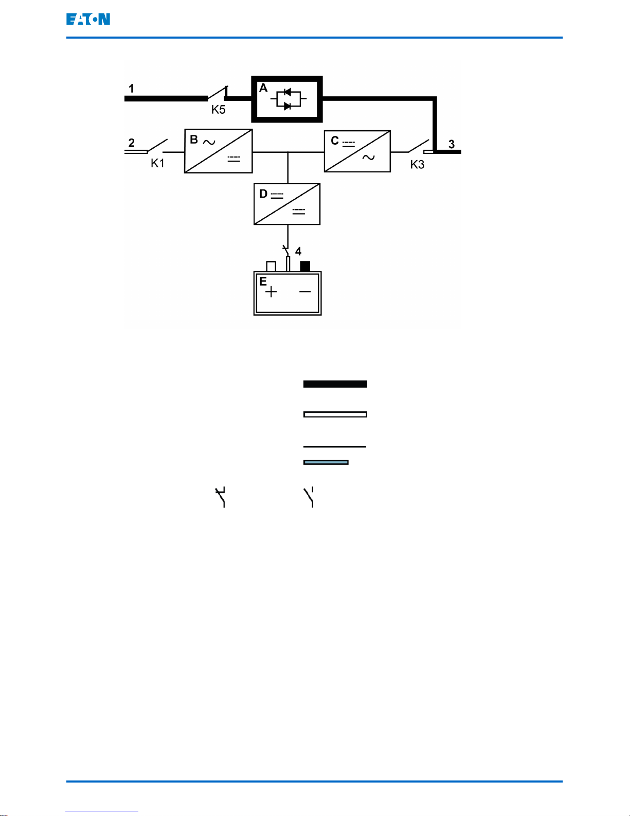
Figure 5. Path of current through the UPS in the bypass mode
A Static
switch
1 Bypass in-
put
Main power flow
B Rectifier 2 Rectifier in-
put
Energized
C Inverter 3 Output De-energized
D Battery con-
verter
4 Battery
breaker
Trickle current
E Battery Closed Open
In the bypass mode, the output of the system is provided with three-phase AC
power directly from the system input. While in this mode, the output of the
system is not protected from voltage or frequency fluctuations or power outages
from the source. Some power line filtering and transient protection is provided to
the load, but no active power conditioning or battery support is available to the
output of the system in the bypass mode.
The static bypass consists of a solid-state, silicon-controlled rectifier (SCR)
static switch (STSW) and a backfeed protection isolation device K5. The static
switch is rated as a continuous-duty device that is used anytime the inverter is
unable to support the applied load. The static switch is wired in series with the
backfeed protection. As the static switch is an electronically-controlled device, it
can be turned on immediately to pick up the load from the inverter without
interruption. The backfeed protection is normally always closed, ready to
support the static switch unless the bypass input source becomes unavailable.
Eaton 93PM UPS 30–200 kVA
User's and installation guide
©
Eaton Corporation plc 2017. All rights reserved. Revision: 005 Document ID: P-164000249 26 (126)

3.3 UPS features
The Eaton UPS has many features that provide cost-effective and consistently
reliable power protection. The feature descriptions provide a brief overview of
the UPS standard features.
3.3.1 Advanced Battery Management
The Advanced Battery Management technology uses sophisticated sensing
circuitry and a three-stage charging technique that extends the useful service
life of UPS batteries while optimizing the battery recharge time. ABM also
protects batteries from damage caused by high current charging and inverter
ripple currents. Charging at high currents can overheat and damage batteries.
In the
charge mode
, the batteries are recharged. Charging lasts only as long as
it takes to bring the battery system up to a predetermined float level. Once this
level is reached, the UPS battery charger enters the
float stage
and the charger
operates in the constant voltage mode.
The
rest mode
begins at the end of the charge mode; that is, after 48 hours of
float charging (user-adjustable). In the rest mode, the battery charger is
completely turned off. The battery system receives no charge current during this
rest period of approximately 28 days (user-adjustable). During the rest mode,
the open circuit battery voltage is monitored constantly, and battery charging is
resumed when necessary.
3.3.2 Powerware Hot Sync
The Eaton Powerware Hot Sync technology is an algorithm that eliminates the
single point of failure in a parallel system and therefore enhances system
reliability. The Hot Sync technology is incorporated in all Eaton 93PM UPSs,
and it is utilized in both multi-module internal parallel and external parallel
systems.
The Hot Sync technology enables all UPMs to operate independently in a
parallel system, even without inter-module communications. The power modules
utilizing the Hot Sync technology are completely autonomous; each module
monitors its own output independently to remain in complete synchronization
with the other modules. The UPM power modules share the load perfectly even
in changing capacity or load conditions.
The Powerware Hot Sync technology combines digital signal processing and an
advanced control algorithm to provide automatic load sharing and selective
tripping in a parallel UPS system. The load share control algorithms maintain
synchronization and load balance by constantly making minute adjustments to
variations in the output power requirements. The modules conform to demand
and are not in conflict with each other for the load. The Powerware Hot Sync
systems are capable of paralleling for both redundancy and capacity.
Eaton 93PM UPS 30–200 kVA
User's and installation guide
©
Eaton Corporation plc 2017. All rights reserved. Revision: 005 Document ID: P-164000249 27 (126)

3.3.3 Power Conditioner
The Power Conditioner mode is characterized by the UPS running in the double
conversion mode without batteries connected. In the Power Conditioner mode,
the UPS provides conditioned output voltage and frequency. The UPS can also
support high nonlinear loads without ITHD on the input. The UPS meets the
qualifications outlined in this product specification, except for the conditions
below.
When in the Power Conditioner mode, the UPS has the following functionality
and limitations:
1. The UPS runs in the double conversion mode.
2. Because there is no battery, loss of utility power results in the UPS losing
power and shutting down.
3. The UPS sustains up to -50% input voltage tolerance, unless the current
limit is reached.
4. If the rectifier is turned off, the UPS attempts a transfer to the bypass
mode.
5. The ESS mode is not available.
6. The Power Conditioner mode is available in both 3 and 4 wire
configurations.
3.3.4 Frequency Converter
The Frequency Converter mode is characterized by the UPS running without the
bypass mode available. The output frequency can be configured to be different
from the standard input frequency (e.g. 60 Hz output, 50 Hz input). The UPS
can also support high nonlinear loads without iTHD on the input. The UPS
meets the qualifications outlined in this product specification, except for the
conditions below.
When in the Frequency Converter mode, the UPS has the following functionality
and limitations:
1. Operation is the same as when in the double conversion mode with no
bypass available.
2. Bypass alarms are suppressed.
3.3.5 Sync Control
The Eaton® Sync Control maintains the critical load outputs of two separate
UPS systems in synchronization. Use of the Eaton Fixed Master Sync Control
provides uninterrupted transfer of the load from one load bus to another by
means of downstream, dual-source, solid-state transfer switches. Without the
load sync option, the two system output (critical load) buses can become out of
phase with each other. This condition occurs when suitable bypass sources are
not available or when the bypass sources feeding each system are not in sync
with each other. Examples of this condition are two systems supplied by
Eaton 93PM UPS 30–200 kVA
User's and installation guide
©
Eaton Corporation plc 2017. All rights reserved. Revision: 005 Document ID: P-164000249 28 (126)

separate generator sets, or situation where the bypass sources for the two
systems are lost.
3.4 Software and connectivity features
3.4.1 User interface
MiniSlot Communication Bays — there are 3 communication bays for MiniSlot
connectivity cards. MiniSlot cards are quickly installed and hot-pluggable. See
Chapter
6
for additional information.
3.4.2 Power Management Software
Intelligent Power software products offer tools for monitoring and managing
power devices across the network. See Chapter
6
for more information.
3.5 Options and accessories
Contact your Eaton sales representative for more information about the
available options and accessories.
3.5.1 Maintenance Bypass Switch
The Maintenance Bypass Switch (MBS) enables power to completely bypass
and isolate the UPS so that the UPS can be safely serviced or replaced without
interrupting power to critical systems.
An internal maintenance bypass switch is provided as a factory installed option
for 30–150 kW units.
Alternatively, MBS solutions are also available in an external enclosure as
accessory items.
External Maintenance Bypass Switch Panel
The external MBS is enclosed in its own separate cabinet, which can be either a
wall-mounted or stand-alone cabinet depending on the MBS power rating. The
MBS includes a Maintenance Bypass Switch (MBS) and a UPS Output
Maintenance Isolation Switch (MIS). The panel may additionally include one or
two input breakers: one for the rectifier input (RIB) and another for bypass input
(BIB). It also includes auxiliary contacts to report the status of the switchgear to
the UPS.
For external MBS installation instructions, see a separate manual.
Eaton 93PM UPS 30–200 kVA
User's and installation guide
©
Eaton Corporation plc 2017. All rights reserved. Revision: 005 Document ID: P-164000249 29 (126)

3.5.2 93PM 200 kW SIAC-MBS
The side integrated accessory cabinet (SIAC-MBS) for 160-200 kW 93PM
includes a mechanical maintenance bypass switch and 1 or 2 input breakers for
dual or single feed installation.
3.5.3 Top air exhaust kit
The top air exhaust kit is used to direct the UPS cooling air front-to-top. The kit
will eliminate the cooling clearance requirement from the back of the unit, and
enable installing the UPS even against a wall, in a corner or back-to-back. The
kit increases the depth of the unit by 200 mm.
Refer to Section
4.3
for further information.
3.5.4 Top cable access kit
The top cable access kit is designed to support top cabling to the 30-150 kW
93PM UPS in sites where the cabling is distributed through overhead cable
trays. The kit is installed at the right hand side of the UPS unit.
The 200 kW 93PM UPS does not require this kit, since the unit supports bottom,
rear, and top cable entry by standard.
Refer to Section
4.3
, Section
5.1
and Figure
14
for further information.
3.5.5 Single feed kit
The Eaton 93PM UPS is configured for dual feed by standard, requiring a
separate feed for rectifier and static bypass input. Single feed kits are available
for 80–200kW models for on-site installation. In addition, a single feed
configuration can be fitted to the 30–50kW models using jumper-cables during
installation.
3.5.6 Separate battery option
By standard, the Eaton 93PM UPS has one external battery connection, through
which external batteries supply all UPMs. If needed, the external battery
connections can be ordered as a separate battery configuration for the multimodular 80–200kW models. This option enables connecting a separate external
battery to each 50 kW UPM. See Section
5.4.1
for more information.
3.5.7 Field Installed UPM
A Field Installed UPM (F-UPM) can be installed in the cabinet any time in the
future when power needs change. This enables the UPS system to grow with
the business, thus lowering the initial investment necessary for the system on
day one.
Eaton 93PM UPS 30–200 kVA
User's and installation guide
©
Eaton Corporation plc 2017. All rights reserved. Revision: 005 Document ID: P-164000249 30 (126)
 Loading...