

Eaton 93E 30ITC, 93E 60ITC Installation Manual

Eaton® 93E Integrated Transformer Cabinet
30ITC and 60ITC
Installation Manual


Eaton® 93E Integrated Transformer Cabinet
30ITC and 60ITC
Installation Manual

IMPORTANT SAFETY INSTRUCTIONS SAVE THESE INSTRUCTIONS
This manual contains important instructions that should be followed during installation and
CONSIGNES DE SÉCURITÉ IMPORTANTES CONSERVER CES INSTRUCTIONS
maintenance of the UPS system and batteries. Read all instructions before operating the
equipment and save this manual for future reference.
Ce manuel comporte des instructions importantes que vous êtes invité à suivre lors de toute
procédure d'installation et de maintenance des batteries et de l'onduleur. Veuillez consulter
entièrement ces instructions avant de faire fonctionner l'équipement et conserver ce manuel afin
de pouvoir vous y reporter ultérieurement.
Eaton is a registered trademarks of Eaton Corporation or its subsidiaries and affiliates. National Electrical Code
and NEC are registered trademarks of National Fire Protection Association, Inc. All other trademarks are
property of their respective companies.
©Copyright 2011–2015 Eaton Corporation, Raleigh, NC, USA. All rights reserved. No part of this document may
be reproduced in any way without the express written approval of Eaton Corporation.

Table of Contents
1 INTRODUCTION . . . . . . . . . . . . . . . . . . . . . . . . . . . . . . . . . . . . . . . . . . . . . . . . . . . . . . . . . . . . . . . . . . . . . . . . . . . . . . . . . . . . . . 1-1
1.1 Installation Features . . . . . . . . . . . . . . . . . . . . . . . . . . . . . . . . . . . . . . . . . . . . . . . . . . . . . . . . . . . . . . . . . . . 1-2
1.2 Model Configurations . . . . . . . . . . . . . . . . . . . . . . . . . . . . . . . . . . . . . . . . . . . . . . . . . . . . . . . . . . . . . . . . . . 1-2
1.3 Using This Manual. . . . . . . . . . . . . . . . . . . . . . . . . . . . . . . . . . . . . . . . . . . . . . . . . . . . . . . . . . . . . . . . . . . . . 1-4
1.4 Conventions Used in This Manual. . . . . . . . . . . . . . . . . . . . . . . . . . . . . . . . . . . . . . . . . . . . . . . . . . . . . . . . . 1-4
1.5 Symbols, Controls, and Indicators. . . . . . . . . . . . . . . . . . . . . . . . . . . . . . . . . . . . . . . . . . . . . . . . . . . . . . . . . 1-4
1.6 For More Information . . . . . . . . . . . . . . . . . . . . . . . . . . . . . . . . . . . . . . . . . . . . . . . . . . . . . . . . . . . . . . . . . . 1-5
1.7 Getting Help . . . . . . . . . . . . . . . . . . . . . . . . . . . . . . . . . . . . . . . . . . . . . . . . . . . . . . . . . . . . . . . . . . . . . . . . . 1-5
2 SAFETY WARNINGS . . . . . . . . . . . . . . . . . . . . . . . . . . . . . . . . . . . . . . . . . . . . . . . . . . . . . . . . . . . . . . . . . . . . . . . . . . . . . . . . . . 2-1
3 INSTALLATION PLAN AND UNPACKING . . . . . . . . . . . . . . . . . . . . . . . . . . . . . . . . . . . . . . . . . . . . . . . . . . . . . . . . . . . . . . . . 3-1
3.1 Creating an Installation Plan . . . . . . . . . . . . . . . . . . . . . . . . . . . . . . . . . . . . . . . . . . . . . . . . . . . . . . . . . . . . . 3-1
3.2 Preparing the Site . . . . . . . . . . . . . . . . . . . . . . . . . . . . . . . . . . . . . . . . . . . . . . . . . . . . . . . . . . . . . . . . . . . . . 3-1
3.2.1 Environmental and Installation Considerations . . . . . . . . . . . . . . . . . . . . . . . . . . . . . . . . . . . . . . . . . . 3-1
3.2.2 ITC Power Wiring Preparation . . . . . . . . . . . . . . . . . . . . . . . . . . . . . . . . . . . . . . . . . . . . . . . . . . . . . . . 3-9
3.3 Inspecting and Unpacking the ITC. . . . . . . . . . . . . . . . . . . . . . . . . . . . . . . . . . . . . . . . . . . . . . . . . . . . . . . . . 3-14
3.4 Transformer Breaker Location. . . . . . . . . . . . . . . . . . . . . . . . . . . . . . . . . . . . . . . . . . . . . . . . . . . . . . . . . . . . 3-16
4 INSTALLATION. . . . . . . . . . . . . . . . . . . . . . . . . . . . . . . . . . . . . . . . . . . . . . . . . . . . . . . . . . . . . . . . . . . . . . . . . . . . . . . . . . . . . . . 4-1
4.1 Preliminary Installation Information . . . . . . . . . . . . . . . . . . . . . . . . . . . . . . . . . . . . . . . . . . . . . . . . . . . . . . . . 4-1
4.2 Unloading the ITC from the Pallet . . . . . . . . . . . . . . . . . . . . . . . . . . . . . . . . . . . . . . . . . . . . . . . . . . . . . . . . . 4-1
4.2.1 Unloading the 30ITC . . . . . . . . . . . . . . . . . . . . . . . . . . . . . . . . . . . . . . . . . . . . . . . . . . . . . . . . . . . . . . 4-1
4.2.2 Unloading the 60ITC . . . . . . . . . . . . . . . . . . . . . . . . . . . . . . . . . . . . . . . . . . . . . . . . . . . . . . . . . . . . . . 4-5
4.3 Installing the Power Terminal Cover Base. . . . . . . . . . . . . . . . . . . . . . . . . . . . . . . . . . . . . . . . . . . . . . . . . . . 4-8
4.4 Installing ITC External Power Wiring . . . . . . . . . . . . . . . . . . . . . . . . . . . . . . . . . . . . . . . . . . . . . . . . . . . . . . . 4-10
4.4.1 Single-Feed UPS with Input Transformer . . . . . . . . . . . . . . . . . . . . . . . . . . . . . . . . . . . . . . . . . . . . . . 4-10
4.4.2 Single-Feed UPS with Input and Output Transformers . . . . . . . . . . . . . . . . . . . . . . . . . . . . . . . . . . . . 4-20
4.4.3 Dual-Feed UPS with Two Input Transformers . . . . . . . . . . . . . . . . . . . . . . . . . . . . . . . . . . . . . . . . . . . 4-23
4.4.4 Dual-Feed UPS with Two Input Transformers and One Output Transformer . . . . . . . . . . . . . . . . . . . 4-24
4.5 Initial Startup . . . . . . . . . . . . . . . . . . . . . . . . . . . . . . . . . . . . . . . . . . . . . . . . . . . . . . . . . . . . . . . . . . . . . . . . . 4-27
4.6 Completing the Installation Checklist . . . . . . . . . . . . . . . . . . . . . . . . . . . . . . . . . . . . . . . . . . . . . . . . . . . . . . 4-27
5 ONELINES AND SCHEMATICS . . . . . . . . . . . . . . . . . . . . . . . . . . . . . . . . . . . . . . . . . . . . . . . . . . . . . . . . . . . . . . . . . . . . . . . . . 5-1
5.1 Onelines . . . . . . . . . . . . . . . . . . . . . . . . . . . . . . . . . . . . . . . . . . . . . . . . . . . . . . . . . . . . . . . . . . . . . . . . . . . . 5-1
5.2 Schematics . . . . . . . . . . . . . . . . . . . . . . . . . . . . . . . . . . . . . . . . . . . . . . . . . . . . . . . . . . . . . . . . . . . . . . . . . . 5-3
6 MAINTENANCE . . . . . . . . . . . . . . . . . . . . . . . . . . . . . . . . . . . . . . . . . . . . . . . . . . . . . . . . . . . . . . . . . . . . . . . . . . . . . . . . . . . . . . 6-1
6.1 Important Safety Instructions . . . . . . . . . . . . . . . . . . . . . . . . . . . . . . . . . . . . . . . . . . . . . . . . . . . . . . . . . . . . 6-1
6.2 Performing Preventive Maintenance. . . . . . . . . . . . . . . . . . . . . . . . . . . . . . . . . . . . . . . . . . . . . . . . . . . . . . . 6-1
6.2.1 DAILY Maintenance. . . . . . . . . . . . . . . . . . . . . . . . . . . . . . . . . . . . . . . . . . . . . . . . . . . . . . . . . . . . . . . 6-1
6.2.2 PERIODIC Maintenance . . . . . . . . . . . . . . . . . . . . . . . . . . . . . . . . . . . . . . . . . . . . . . . . . . . . . . . . . . . 6-1
6.2.3 ANNUAL Maintenance . . . . . . . . . . . . . . . . . . . . . . . . . . . . . . . . . . . . . . . . . . . . . . . . . . . . . . . . . . . . 6-1
6.3 Recycling the ITC . . . . . . . . . . . . . . . . . . . . . . . . . . . . . . . . . . . . . . . . . . . . . . . . . . . . . . . . . . . . . . . . . . . . . 6-2
6.4 Maintenance Training . . . . . . . . . . . . . . . . . . . . . . . . . . . . . . . . . . . . . . . . . . . . . . . . . . . . . . . . . . . . . . . . . . 6-2
Eaton 93E Integrated Transformer Cabinet (ITC) Installation Manual P-164000074—Rev 3 www.eaton.com/powerquality i

Table of Contents
7 PRODUCT SPECIFICATIONS . . . . . . . . . . . . . . . . . . . . . . . . . . . . . . . . . . . . . . . . . . . . . . . . . . . . . . . . . . . . . . . . . . . . . . . . . . . . 7-1
7.1 Model Numbers . . . . . . . . . . . . . . . . . . . . . . . . . . . . . . . . . . . . . . . . . . . . . . . . . . . . . . . . . . . . . . . . . . . . . . . 7-1
7.2 Specifications . . . . . . . . . . . . . . . . . . . . . . . . . . . . . . . . . . . . . . . . . . . . . . . . . . . . . . . . . . . . . . . . . . . . . . . . . 7-1
7.2.1 Input Transformer . . . . . . . . . . . . . . . . . . . . . . . . . . . . . . . . . . . . . . . . . . . . . . . . . . . . . . . . . . . . . . . . . 7-1
7.2.2 Output Transformer. . . . . . . . . . . . . . . . . . . . . . . . . . . . . . . . . . . . . . . . . . . . . . . . . . . . . . . . . . . . . . . . 7-1
7.2.3 Environmental and Safety Specifications . . . . . . . . . . . . . . . . . . . . . . . . . . . . . . . . . . . . . . . . . . . . . . . 7-2
WARRANTY . . . . . . . . . . . . . . . . . . . . . . . . . . . . . . . . . . . . . . . . . . . . . . . . . . . . . . . . . . . . . . . . . . . . . . . . . . . . . . . . . . . . . . . . . . . . . . . . W-1
ii Eaton 93E Integrated Transformer Cabinet (ITC) Installation Manual P-164000074—Rev 3 www.eaton.com/powerquality

List of Figures
Figure 1-1. Eaton 93E 30ITC and Eaton 93E 60ITC . . . . . . . . . . . . . . . . . . . . . . . . . . . . . . . . . . . . . . . . . . . . . . . . . . . . . 1-1
Figure 1-3. Eaton 93E 60 kVA UPS and Eaton 93E 60ITC . . . . . . . . . . . . . . . . . . . . . . . . . . . . . . . . . . . . . . . . . . . . . . . . 1-3
Figure 3-1. 93E 30ITC Cabinet Dimensions (Front, Right Side, and Rear Views) . . . . . . . . . . . . . . . . . . . . . . . . . . . . . . 3-3
Figure 3-2. 93E 30ITC Dimensions (Top and Bottom Views) . . . . . . . . . . . . . . . . . . . . . . . . . . . . . . . . . . . . . . . . . . . . . 3-4
Figure 3-3. 93E 30ITC Center of Gravity . . . . . . . . . . . . . . . . . . . . . . . . . . . . . . . . . . . . . . . . . . . . . . . . . . . . . . . . . . . . . 3-5
Figure 3-4. 93E 60ITC Cabinet Dimensions (Front, Right Side, and Rear Views) . . . . . . . . . . . . . . . . . . . . . . . . . . . . . . 3-6
Figure 3-5. 93E 60ITC Dimensions (Top and Bottom Views) . . . . . . . . . . . . . . . . . . . . . . . . . . . . . . . . . . . . . . . . . . . . . 3-7
Figure 3-6. 93E 60ITC Center of Gravity . . . . . . . . . . . . . . . . . . . . . . . . . . . . . . . . . . . . . . . . . . . . . . . . . . . . . . . . . . . . . 3-8
Figure 3-7. Eaton 93E 30ITC and Eaton 93E 60ITC as Shipped on Pallet . . . . . . . . . . . . . . . . . . . . . . . . . . . . . . . . . . . . 3-15
Figure 3-8. Eaton 93E 30ITC and Eaton 93E 60ITC Transformer Breaker
Locations – Front Views with Doors Removed . . . . . . . . . . . . . . . . . . . . . . . . . . . . . . . . . . . . . . . . . . . . . . . 3-16
Figure 4-1. Removing the Front Shipping Bracket – 93E 30ITC . . . . . . . . . . . . . . . . . . . . . . . . . . . . . . . . . . . . . . . . . . . 4-2
Figure 4-2. Removing the Rear Shipping Bracket – 93E 30ITC . . . . . . . . . . . . . . . . . . . . . . . . . . . . . . . . . . . . . . . . . . . . 4-3
Figure 4-3. Installing the Pallet Extension Plate – 93E 30ITC . . . . . . . . . . . . . . . . . . . . . . . . . . . . . . . . . . . . . . . . . . . . . 4-4
Figure 4-4. Removing the Pallet Skids and Supports – 93E 60ITC . . . . . . . . . . . . . . . . . . . . . . . . . . . . . . . . . . . . . . . . . 4-7
Figure 4-5. ITC Power Terminal Cover Parts . . . . . . . . . . . . . . . . . . . . . . . . . . . . . . . . . . . . . . . . . . . . . . . . . . . . . . . . . . 4-8
Figure 4-6. Eaton 93E 30ITC Power Terminal Cover Base Installation and Conduit Wire Entry Location . . . . . . . . . . . . 4-9
Figure 4-7. Eaton 93E 60ITC Power Terminal Cover Base Installation and Conduit Wire Entry Location . . . . . . . . . . . . 4-10
Figure 4-8. Wire Tray Location – 93E 30ITC . . . . . . . . . . . . . . . . . . . . . . . . . . . . . . . . . . . . . . . . . . . . . . . . . . . . . . . . . . 4-12
Figure 4-9. Wire Tray Location – 93E 60ITC . . . . . . . . . . . . . . . . . . . . . . . . . . . . . . . . . . . . . . . . . . . . . . . . . . . . . . . . . . 4-13
Figure 4-10. Input and Output Power Terminal Locations – 93E 30ITC . . . . . . . . . . . . . . . . . . . . . . . . . . . . . . . . . . . . . . 4-14
Figure 4-11. Output Transformer Breaker Terminal Detail – 93E 30ITC . . . . . . . . . . . . . . . . . . . . . . . . . . . . . . . . . . . . . . 4-15
Figure 4-12. Input Transformer Breaker Terminal Detail – 93E 30ITC . . . . . . . . . . . . . . . . . . . . . . . . . . . . . . . . . . . . . . . . 4-15
Figure 4-13. Input and Output Power Terminal Locations – 93E 60ITC . . . . . . . . . . . . . . . . . . . . . . . . . . . . . . . . . . . . . . 4-16
Figure 4-14. Output Transformer Breaker Terminal Detail – 93E 60ITC . . . . . . . . . . . . . . . . . . . . . . . . . . . . . . . . . . . . . . 4-17
Figure 4-15. Input Transformer Breaker Terminal Detail – 93E 60ITC . . . . . . . . . . . . . . . . . . . . . . . . . . . . . . . . . . . . . . . . 4-17
Figure 4-16. ITC and UPS Power Terminal Cover Base Wiring Channel . . . . . . . . . . . . . . . . . . . . . . . . . . . . . . . . . . . . . . 4-18
Figure 4-17. ITC Power Terminal Cover Install . . . . . . . . . . . . . . . . . . . . . . . . . . . . . . . . . . . . . . . . . . . . . . . . . . . . . . . . . 4-19
Figure 4-18. ITC Power Terminal Cover Splice Installation . . . . . . . . . . . . . . . . . . . . . . . . . . . . . . . . . . . . . . . . . . . . . . . . 4-20
Figure 5-1. 93E 30ITC and 93E 60ITC Internal Oneline . . . . . . . . . . . . . . . . . . . . . . . . . . . . . . . . . . . . . . . . . . . . . . . . . . 5-1
Figure 5-2. Dual Transformer 93E 30ITC and 93E 60ITC Intercabinet Interconnection Oneline . . . . . . . . . . . . . . . . . . . 5-2
Figure 5-3. 93E 30ITC and 93E 60ITC Schematic . . . . . . . . . . . . . . . . . . . . . . . . . . . . . . . . . . . . . . . . . . . . . . . . . . . . . . 5-3
Eaton 93E Integrated Transformer Cabinet (ITC) Installation Manual P-164000074—Rev 3 www.eaton.com/powerquality iii

List of Figures
This page intentionally left blank.
iv Eaton 93E Integrated Transformer Cabinet (ITC) Installation Manual P-164000074—Rev 3 www.eaton.com/powerquality

List of Tables
Table 3-1. ITC Weights. . . . . . . . . . . . . . . . . . . . . . . . . . . . . . . . . . . . . . . . . . . . . . . . . . . . . . . . . . . . . . . . . . . . . . . . . . 3-2
Table 3-2. ITC Clearances . . . . . . . . . . . . . . . . . . . . . . . . . . . . . . . . . . . . . . . . . . . . . . . . . . . . . . . . . . . . . . . . . . . . . . . 3-2
Table 3-3. Cooling Requirements During Full Load Operation . . . . . . . . . . . . . . . . . . . . . . . . . . . . . . . . . . . . . . . . . . . . 3-2
Table 3-4. External Power Wiring Requirements for the Eaton 93E 30ITC and 93E 60ITC – Single Transformer . . . . . 3-10
Table 3-5. External Power Wiring Requirements for the Eaton 93E 30ITC and 93E 60ITC – Dual Transformer . . . . . . 3-11
Table 3-6. External Input Power Cable Terminations for the Eaton 93E 30ITC – Single Transformer . . . . . . . . . . . . . . 3-12
Table 3-7. External Input Power Cable Terminations for the Eaton 93E 30ITC – Dual Transformer . . . . . . . . . . . . . . . 3-12
Table 3-8. External Input Power Cable Terminations for the Eaton 93E 60ITC – Single Transformer . . . . . . . . . . . . . . 3-13
Table 3-9. External Input Power Cable Terminations for the Eaton 93E 60ITC – Dual Transformer . . . . . . . . . . . . . . . 3-13
Eaton 93E Integrated Transformer Cabinet (ITC) Installation Manual P-164000074—Rev 3 www.eaton.com/powerquality v

List of Tables
This page intentionally left blank.
vi Eaton 93E Integrated Transformer Cabinet (ITC) Installation Manual P-164000074—Rev 3 www.eaton.com/powerquality
Chapter 1 Introduction
93E 30ITC
93E 60ITC
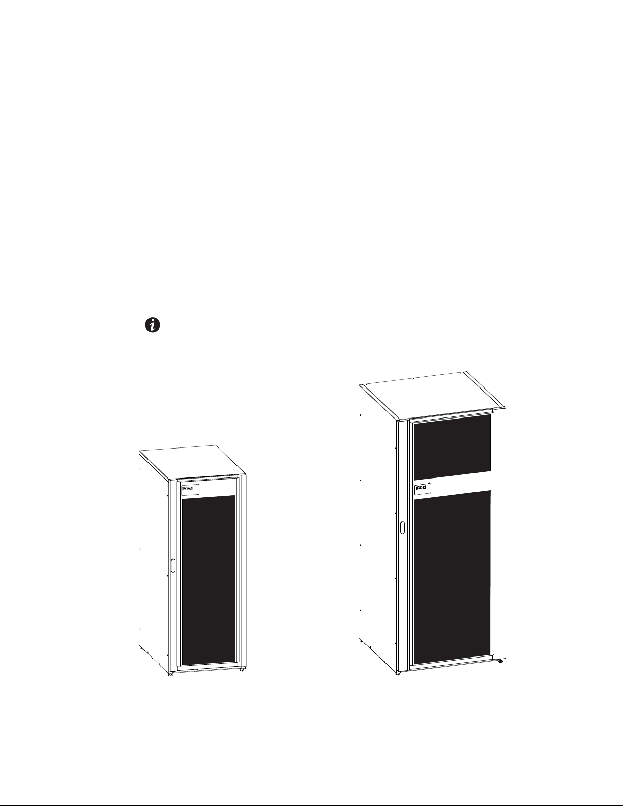
The Eaton® Integrated Transformer Cabinet (ITC) provides voltage transformation and isolation for the
93E 20–30 kVA and 40–60 kVA Uninterruptable Power Supply (UPS) to enhance the usability and reliability of
the systems. Two models are available, the 93E 30ITC and 93E 60ITC to match the installed Eaton 93E UPS.
A 480/208 Vac input isolation transformer provides an isolated input to the UPS rectifier for applications that
require an input of 480 Vac.
An optional 208/480 Vac output isolation transformer provides an isolated output to the critical load or for
applications that require 480 Vac. To save space, the transformer is contained in the same ITC as the input
transformer.
The ITC is housed in a single free-standing cabinet with a safety shield behind the door for hazardous voltage
protection. The cabinets match the UPS cabinet in style and color.
Figure 1-1 shows the Eaton 93E 30ITC and Eaton 93E 60ITC.
NOTE Startup and operational checks must be performed by an authorized Eaton
Customer Service Engineer, or the warranty terms specified on page W-1 become
void. This service is offered as part of the sales contract for the UPS. Contact an
Eaton service representative in advance (usually a two-week notice is required) to
reserve a preferred startup date.
Figure 1-1. Eaton 93E 30ITC and Eaton 93E 60ITC
Eaton 93E Integrated Transformer Cabinet (ITC) Installation Manual P-164000074—Rev 3 www.eaton.com/powerquality 1-1

Introduction
1.1 Installation Features
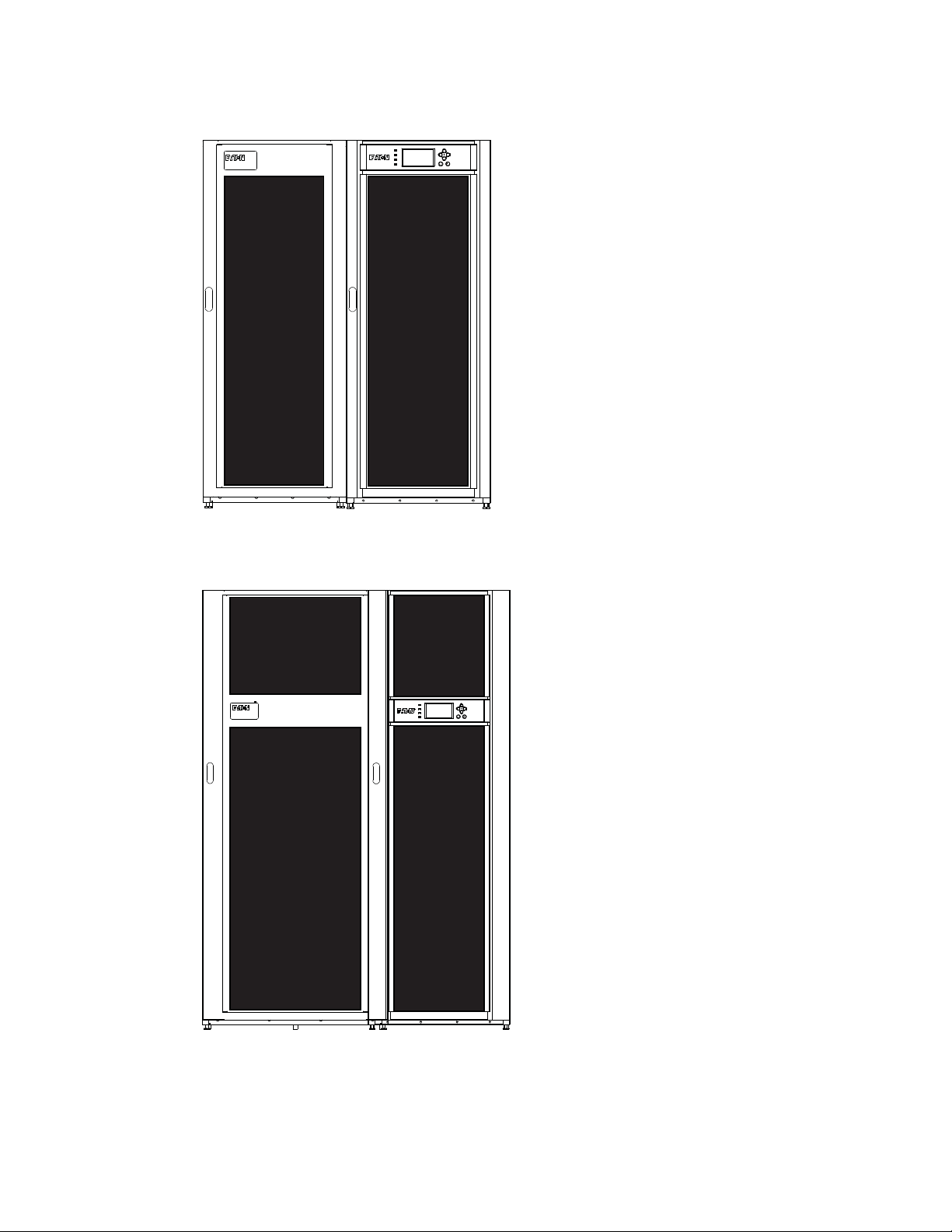
The ITC is designed to be installed in a line-up-and-match or standalone configuration. In a line-up-and-match
configuration power wiring may be routed either external to the cabinet using conduit or the power terminal
wiring channel assembly may be utilized to pass wiring between adjacent cabinets. In standalone
configurations power wiring is routed using external conduit.
To reduce installation time, wiring enters the ITC from the back and is routed to the front panel for easy
connection to the mechanical lugs located on the input and output circuit breakers.
A line-up-and-match ITC is installed adjacent to the UPS or other accessory cabinet. The recommended
installation location is to the left of the UPS cabinet. See Figure 1-2 and Figure 1-3 for line-up-and-match
configuration views.
1.2 Model Configurations
The following model configurations are available:
l
93E 30ITC for use with the 93E 30 kVA UPS
- Single Transformer Cabinet: Contains a three-phase 480 Vac to 208Y/120 Vac input isolation transformer
- Dual Transformer Cabinet: Contains a three-phase 480 Vac to 208Y/120 Vac input isolation transformer
and a three-phase 208 Vac to 480Y/277 Vac output isolation transformer
l
93E 60ITC for use with the 93E 60 kVA UPS
- Single Transformer Cabinet: Contains a three-phase 480 Vac to 208Y/120 Vac input isolation transformer
- Dual Transformer Cabinet: Contains a three-phase 480 Vac to 208Y/120 Vac input isolation transformer
and a three-phase 208 Vac to 480Y/277 Vac output isolation transformer
1-2 Eaton 93E Integrated Transformer Cabinet (ITC) Installation Manual P-164000074—Rev 3 www.eaton.com/powerquality
Introduction
UPS93E 30ITC
UPS93E 60ITC
Figure 1-2. Eaton 93E 30 kVA UPS and Eaton 93E 30ITC
Figure 1-3. Eaton 93E 60 kVA UPS and Eaton 93E 60ITC
Eaton 93E Integrated Transformer Cabinet (ITC) Installation Manual P-164000074—Rev 3 www.eaton.com/powerquality 1-3
Introduction
1.3 Using This Manual
This manual describes how to install the ITC. Read and understand the procedures described to ensure
trouble-free installation and operation.
Read through each procedure before beginning the procedure. Perform only those procedures that apply to the
UPS system being installed or operated.
1.4 Conventions Used in This Manual
This manual uses these type conventions:
l
Bold type highlights important concepts in discussions, key terms in procedures, and menu options, or
represents a command or option that you type or enter at a prompt.
l
Italic type highlights new terms where they are defined.
l
Screen type represents information that appears on the screen or LCD.
Icon Description
NOTE Information notes call attention to important features or instructions.
[Keys] Brackets are used when referring to a specific key, such as [Enter] or [Ctrl].
In this manual, the term UPS refers only to the UPS cabinet and its internal elements. The term UPS system
refers to the entire power protection system – the UPS cabinet, an external battery system, and options or
accessories installed.
The term line-up-and-match refers to accessory cabinets that are physically located adjacent to the UPS. The
term standalone refers to accessory cabinets that are located separate from the UPS.
1.5 Symbols, Controls, and Indicators
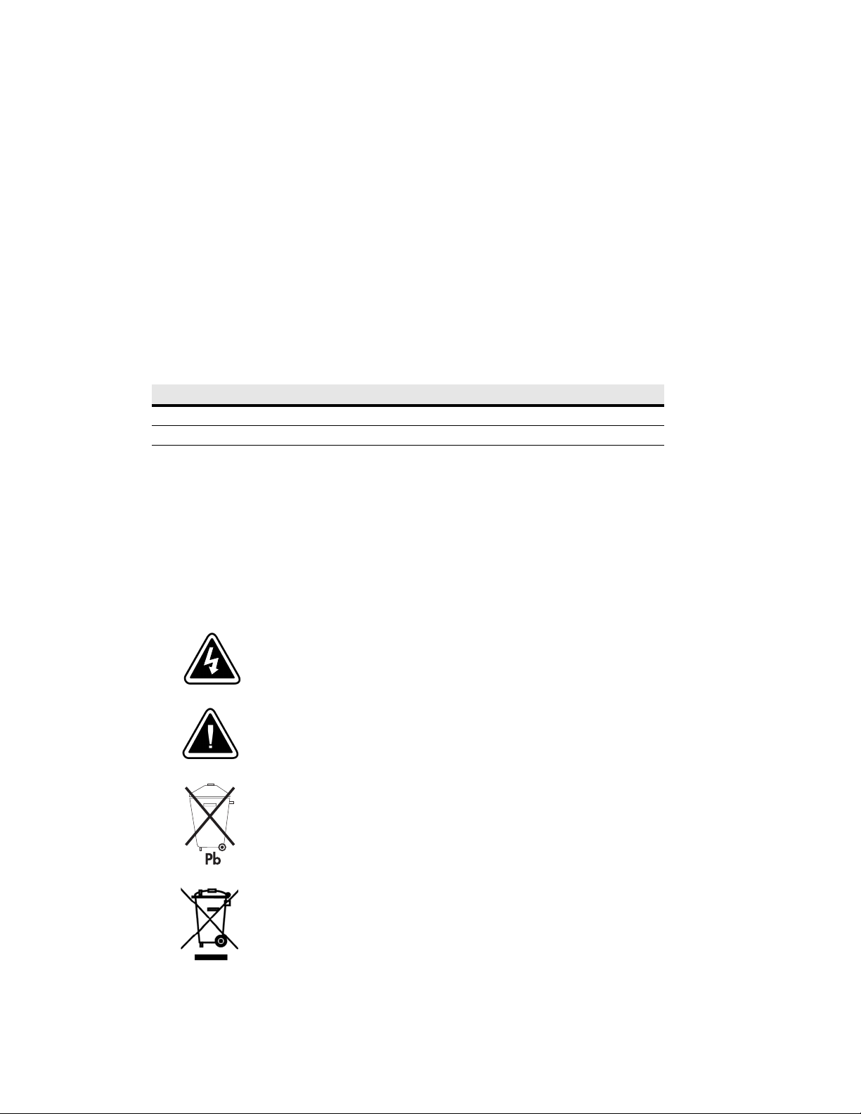
The following are examples of symbols used on the UPS or accessories to alert you to important information:
RISK OF ELECTRIC SHOCK - Observe the warning associated with the risk
of electric shock symbol.
CAUTION: REFER TO OPERATOR'S MANUAL - Refer to your operator's
manual for additional information, such as important operating and
maintenance instructions.
This symbol indicates that you should not discard the UPS or the UPS
batteries in the trash. This product contains sealed, lead-acid batteries and
must be disposed of properly. For more information, contact your local
recycling/reuse or hazardous waste center.
This symbol indicates that you should not discard waste electrical or
electronic equipment (WEEE) in the trash. For proper disposal, contact your
local recycling/reuse or hazardous waste center.
1-4 Eaton 93E Integrated Transformer Cabinet (ITC) Installation Manual P-164000074—Rev 3 www.eaton.com/powerquality

1.6 For More Information
Refer to the Eaton 93E UPS (20-30 kVA, 208/220V) Generation 3 Installation and Operation Manual or
Eaton 93E UPS (40-60 kVA, 208/220V) Generation 3 Installation and Operation Manual for the following
additional information:
l
UPS, optional components, and accessory installation instructions, including site preparation, planning for
installation, and wiring and safety information (detailed illustrations of cabinets and optional accessories with
dimensional and connection point drawings are provided)
l
UPS operation, including UPS controls, functions of the UPS, standard features and optional accessories,
procedures for starting and stopping the UPS, and information about maintenance and responding to
system events
l
Communication capabilities of the UPS system
Refer to the Eaton 93E Integrated Accessory Cabinet-Distribution Installation Manual for the following
additional information:
l
Installation instructions, including site preparation, planning for installation, wiring and safety information,
and detailed illustrations of cabinets with dimensional and connection point drawings
Refer to the Eaton 93E Integrated Accessory Cabinet-Tie and Bypass Installation and Operation Manual for the
following additional information:
Introduction
l
Operation, including breakers, standard features and optional accessories, procedures for using the bypass
functions, and information about maintenance
l
Installation instructions, including site preparation, planning for installation, wiring and safety information,
and detailed illustrations of cabinets with dimensional and connection point drawings
Visit www.eaton.com/powerquality or contact an Eaton service representative for information on how to obtain
copies of these manuals.
1.7 Getting Help
If help is needed with any of the following:
l
Scheduling initial startup
l
Regional locations and telephone numbers
l
A technical question about any of the information in this manual
l
A question this manual does not answer
Please call the Customer Reliability Center at:
United States: 1-800-843-9433
Canada: 1-800-461-9166 ext 260
All other countries: Call your local service representative
Please use the following e-mail address for manual comments, suggestions, or to report an error in this manual:
E-ESSDocumentation@eaton.com
Eaton 93E Integrated Transformer Cabinet (ITC) Installation Manual P-164000074—Rev 3 www.eaton.com/powerquality 1-5

Introduction
This page intentionally left blank.
1-6 Eaton 93E Integrated Transformer Cabinet (ITC) Installation Manual P-164000074—Rev 3 www.eaton.com/powerquality

Chapter 2 Safety Warnings
IMPORTANT SAFETY INSTRUCTIONS SAVE THESE INSTRUCTIONS
DANGER
WARNING
CAUTION
This manual contains important instructions that should be followed during installation and
maintenance of the UPS system and batteries. Read all instructions before operating the
equipment and save this manual for future reference.
The UPS system is designed for industrial or computer room applications, and contains safety
shields behind the door and front panels. However, the UPS system is a sophisticated power
system and should be handled with appropriate care.
This UPS system contains LETHAL VOLTAGES. All repairs and service should be performed by
AUTHORIZED SERVICE PERSONNEL ONLY. There are NO USER SERVICEABLE PARTS inside the
UPS.
l
The UPS system is powered by its own energy source (batteries). The output terminals may
carry live voltage even when the UPS is disconnected from an AC source.
l
To reduce the risk of fire or electric shock, install this UPS system in a temperature and humidity
controlled, indoor environment, free of conductive contaminants. Ambient temperature must
not exceed 30C (86F). Do not operate near water or excessive humidity (95% maximum). The
system is not intended for outdoor use.
l
As a result of the connected loads, high leakage current is possible. Connection to earth ground
is required for safety and proper product operation. Do not check UPS system operation by any
action that includes removal of the earth (ground) connection with loads attached.
l
Ensure all power is disconnected before performing installation or service.
l
ELECTRIC ENERGY HAZARD. Do not attempt to alter any UPS system or battery wiring or
connectors. Attempting to alter wiring can cause injury.
l
Installation or servicing should be performed by qualified service personnel knowledgeable of
UPS and battery systems, and required precautions. Keep unauthorized personnel away from
equipment. Consider all warnings, cautions, and notes before installing or servicing equipment.
l
Keep the Accessory cabinet doors closed and front panels installed to ensure proper cooling
airflow and to protect personnel from dangerous voltages inside the unit.
l
Do not install or operate the UPS system close to gas or electric heat sources.
l
The operating environment should be maintained within the parameters stated in this manual.
l
Keep surroundings uncluttered, clean, and free from excess moisture.
l
Observe all DANGER, WARNING, and CAUTION notices affixed to the inside and outside of the
equipment.
Eaton 93E Integrated Transformer Cabinet (ITC) Installation Manual P-164000074—Rev 3 www.eaton.com/powerquality 2-1

Safety Warnings
This page intentionally left blank.
2-2 Eaton 93E Integrated Transformer Cabinet (ITC) Installation Manual P-164000074—Rev 3 www.eaton.com/powerquality

Chapter 3 Installation Plan and Unpacking
Use the following basic sequence of steps to install the Eaton 93E 30 or Eaton 93E 60 Integrated Transformer
Cabinet (ITC):
1. Create an installation plan for the ITC (Chapter 3).
2. Prepare your site for the ITC (Chapter 3).
3. Inspect and unpack the ITC (Chapter 3).
4. Unload and install the ITC, and wire the system (Chapter 4).
5. Complete the Installation Checklist (Chapter 4).
6. Have authorized service personnel perform preliminary operational checks and start up the system.
NOTE Startup and operational checks must be performed by an authorized Eaton
Customer Service Engineer, or the warranty terms specified on page W-1 become
void. This service is offered as part of the sales contract for the UPS. Contact an
Eaton service representative in advance (usually a two-week notice is required) to
reserve a preferred startup date.
3.1 Creating an Installation Plan
Before installing the ITC, read and understand how this manual applies to the system being installed. Use the
procedures and illustrations in this section to create a logical plan for installing the ITC. This section contains
the following information:
l
Physical features and requirements, including dimensions
l
Power wiring installation notes
l
Location of conduit and wire entry landing plates
l
Location of power terminals
3.2 Preparing the Site
For the UPS system to operate at peak efficiency, the installation site should meet the environmental
parameters outlined in this manual. If the UPS system is to be operated at an altitude higher than 1500m
(5000 ft), contact an Eaton service representative for important information about high altitude operation. The
operating environment must meet the weight, clearance, and environmental requirements specified for the
applicable accessory cabinet.
3.2.1 Environmental and Installation Considerations
The UPS system installation, including the ITC, must meet the following guidelines:
l
The system must be installed on a level floor suitable for computer or electronic equipment.
l
The system must be installed in a temperature and humidity controlled indoor area free of conductive
contaminants.
Failure to follow guidelines may void your warranty.
The ITC operating environment must accommodate the weight requirements shown in Table 3-1 and the size
requirements shown in Figure 3-1 through Figure 3-6.
Eaton 93E Integrated Transformer Cabinet (ITC) Installation Manual P-164000074—Rev 3 www.eaton.com/powerquality 3-1

Installation Plan and Unpacking
Table 3-1. ITC Weights
Model
Eaton 93E 30ITC with Input Transformer 250 (551) 225 (496) 8 at 28 (62)
Eaton 93E 30ITC with Input and Output Transformer 403 (889) 378 (834) 8 at 47 (104)
Eaton 93E 60ITC with Input Transformer 450 (993) 416 (918) 12 at 35 (77)
Eaton 93E 60ITC with Input and Output Transformer 690 (1521) 656 (1446) 12 at 54 (120)
The 93E 30ITC uses forced air cooling and the 93E 60ITC uses convection cooling to regulate internal
component temperature. Air inlets are in the front of the cabinet and outlets are in the back of the cabinet. Allow
clearance in front of and in back of the cabinet for proper air circulation. The clearances required around the
ITCs are shown in Table 3-2.
Table 3-2. ITC Clearances
From Top of Cabinet 304.8 mm (12") working space
From Front of Cabinet 914.4 mm (36") working space
From Back of Cabinet 914.4 mm (36") working space
From Right Side of Cabinet None Required
From Left Side of Cabinet None Required
Weight
kg (lb)
Shipping Installed Point Loading
The basic environmental requirements for operation of the ITC are:
- Recommended Operating Range: 15–25C (59–77F)
- Maximum Relative Humidity: 95%, noncondensing
The ITC cooling requirements are shown in Table 3-3.
Table 3-3. Cooling Requirements During Full Load Operation
Rating Transformer Voltage Heat Rejection
Model kVA Type Input Output Watts BTU/hr x 1000 Kg-cal/hr
Eaton 93E 30ITC with Input Transformer 30 Input 480 208Y/120 2350 8.0 2022
Eaton 93E 30ITC with Input and Output Transformer 30
Eaton 93E 60ITC with Input Transformer 60 Input 480 208Y/120 2289 7.8 1970
Eaton 93E 60ITC with Input and Output Transformer 60
Input 480 208Y/120
Output 208 480Y/277
Input 480 208Y/120
Output 208 480Y/277
3486 11.9 2999
5274 18.0 4538
3-2 Eaton 93E Integrated Transformer Cabinet (ITC) Installation Manual P-164000074—Rev 3 www.eaton.com/powerquality
Installation Plan and Unpacking
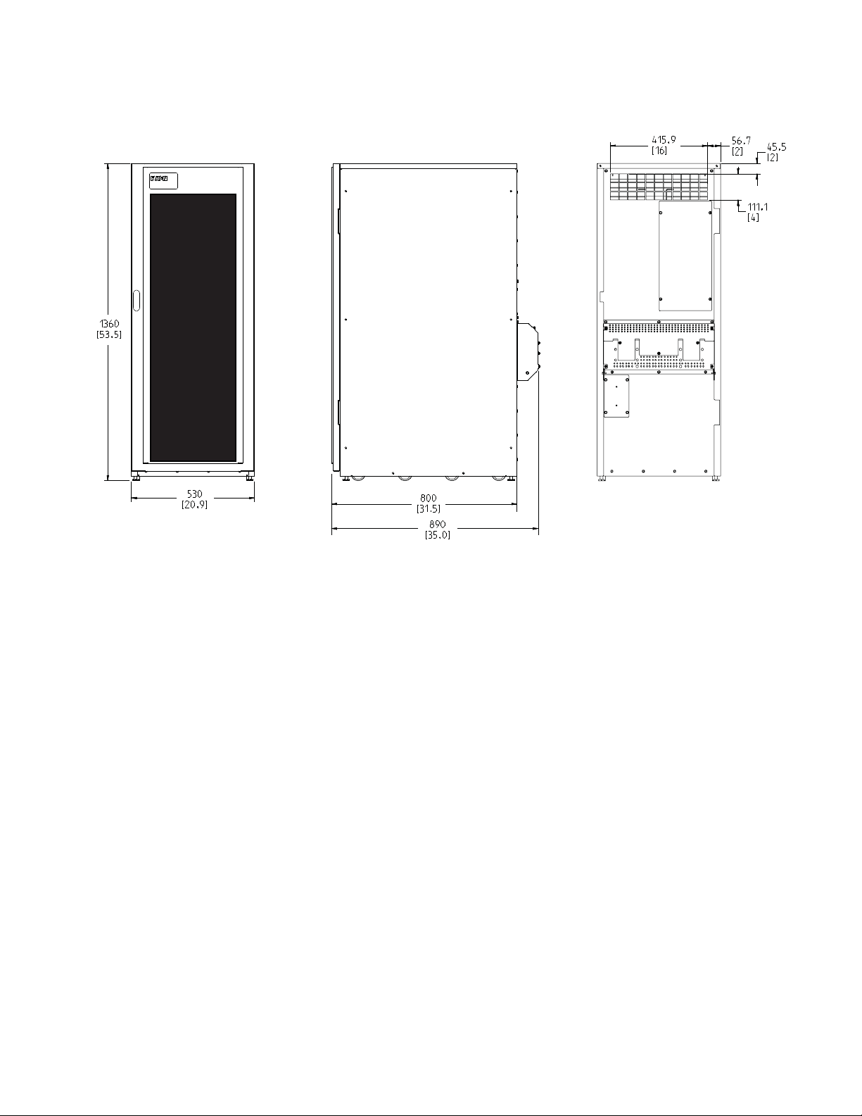
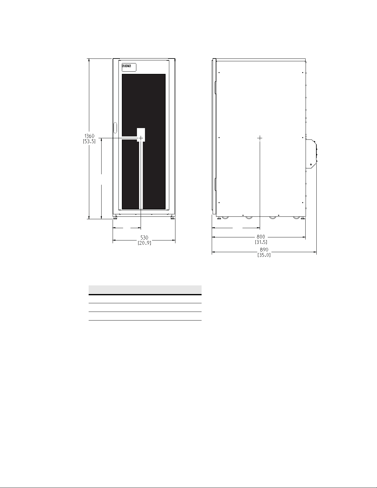
Dimensions are in millimeters [inches]
Figure 3-1. 93E 30ITC Cabinet Dimensions (Front, Right Side, and Rear Views)
Eaton 93E Integrated Transformer Cabinet (ITC) Installation Manual P-164000074—Rev 3 www.eaton.com/powerquality 3-3

Installation Plan and Unpacking
Dimensions are in millimeters [inches]
Figure 3-2. 93E 30ITC Dimensions (Top and Bottom Views)
3-4 Eaton 93E Integrated Transformer Cabinet (ITC) Installation Manual P-164000074—Rev 3 www.eaton.com/powerquality
Installation Plan and Unpacking
Dimensions are in millimeters [inches]
Center of Gravity
ABC
Single Transformer 425 (16.7) 416 (16.4) 280 (11.0)
Dual Transformer 675 (26.6) 416 (16.4) 270 (10.6)
CG
B
A
C
Figure 3-3. 93E 30ITC Center of Gravity
Eaton 93E Integrated Transformer Cabinet (ITC) Installation Manual P-164000074—Rev 3 www.eaton.com/powerquality 3-5
 Loading...