

Eaton 93E Installation And Operation Manual
INSTALLATION AND
Eaton 93E UPS
15-80 kVA (380/400/415 V)
614-01975-00
OPERATION MANUAL

Eaton 93E UPS 15-80 kVA (380/400/415 V) Installation and Operation Manual
Eaton Power Quality Oy
Address:
Internet:
REVISION
DATE
DESCRIPTION OF CHANGE
APPROVED BY
001
28.09.2015
First issue
Otto Asunmaa
Copyright © 2015 Eaton Corporation. All rights reserved.
This manual contains important instructions that you should follow during
installation and maintenance of the UPS and batteries. Please read all instructions
before operating the equipment and save this manual for future reference.
The contents of this manual are the copyright of the publisher and may not be
reproduced (even extracts) without the written approval of Eaton Corporation.
Every care has been taken to ensure the accuracy of the information contained in
this manual, but no liability can be accepted for any errors or omission. The right
to make design modifications is reserved.
Unauthorized copying and lending are prohibited.
Koskelontie 13
FI-02920 Espoo
Finland
www.eaton.eu
Approvals and version history
Original instructions _X_ / Translation of the original instructions ___
© Eaton Corporation plc 2015. All rights reserved. Revision: 001
Document ID: 614-01975-00
3 (133)

Contents
Eaton 93E UPS 15-80 kVA (380/400/415 V) Installation and Operation Manual
Contents ..................................................................................................................4
1 How to read this manual .............................................................................8
1.1 Safety-related signs ....................................................................... 8
1.2 Safety symbols .............................................................................. 8
1.2.1 Hazard symbols ................................................................ 8
1.2.3 Prohibited action symbols ................................................. 9
1.2.4 Mandatory action symbols ................................................ 9
1.3 Conventions used in this document .............................................. 9
2 Safety instructions ........................................................................................11
2.1 Audience ....................................................................................... 14
2.2 CE marking .................................................................................... 14
2.3 User precautions ........................................................................... 14
2.4 Environment .................................................................................. 15
2.5 Using this manual .......................................................................... 16
2.6 Symbols on the UPS and accessories ........................................... 17
2.7 For more information ..................................................................... 17
3 Introduction to Eaton UPS ..........................................................................19
3.1 UPS standard features .................................................................. 20
3.1.1 Installation features........................................................... 20
3.1.2 Control panel .................................................................... 20
3.1.3 Communication interface .................................................. 21
3.1.4 High-efficiency mode ........................................................ 21
3.1.5 Advanced Battery Management ........................................ 21
3.1.6 Maintenance bypass ......................................................... 21
3.2 Options and accessories ............................................................... 21
3.2.1 External battery cabinet .................................................... 22
3.2.2 Parallel system .................................................................. 22
3.2.3 Monitoring and communication ......................................... 22
3.2.4 Single feed ........................................................................ 23
3.3 Battery system .............................................................................. 23
3.4 Basic system configurations .......................................................... 23
4 UPS installation plan and unpacking .........................................................24
4.1 Creating an installation plan ........................................................... 25
4.2 Installation checklist ...................................................................... 25
4.2.1 Parallel system installation checklist ................................. 26
4.3 Site preparations ........................................................................... 27
4.3.1 Environmental and installation considerations ................... 27
4.3.2 UPS system power cabling preparation ............................ 38
© Eaton Corporation plc 2015. All rights reserved. Revision: 001
Document ID: 614-01975-00
4 (133)

Eaton 93E UPS 15-80 kVA (380/400/415 V) Installation and Operation Manual
4.3.3 UPS system interface wiring preparation .......................... 45
4.4 Inspecting and unpacking the UPS cabinets .................................. 46
5 UPS system installation ...............................................................................49
5.1 Preliminary installation information ................................................ 49
5.2 Unloading the UPS cabinet from the pallet .................................... 49
5.3 External power cabling installation................................................. 52
5.4 Battery system installation ............................................................ 56
5.4.1 External battery cabinet installation ................................... 57
5.4.2 1 + 1 common battery system .......................................... 59
5.5 Installing interface connections ..................................................... 60
5.5.1 Installing signal input connections ..................................... 61
5.6 Installing parallel wiring and connections ....................................... 64
5.6.1 Installing MiniSlot interface connections ........................... 68
5.7 Installing a remote EPO switch ..................................................... 68
5.8 Initial startup ................................................................................. 72
5.9 Completing the installation checklist ............................................. 72
6 Understanding UPS operation ...................................................................73
6.1 UPS system overview ................................................................... 73
6.2 Single UPS .................................................................................... 73
6.2.1 Modes .............................................................................. 74
6.2.2 Standard normal mode ...................................................... 74
6.2.3 High-efficiency mode ........................................................ 76
6.2.4 Bypass mode .................................................................... 76
6.2.5 Battery mode .................................................................... 78
6.3 Single UPS unit system oneline configurations .............................. 80
7 UPS operating instructions ..........................................................................83
7.1 UPS controls and indicators ........................................................... 83
7.1.1 Control panel .................................................................... 85
7.2 Using the control panel ................................................................. 85
7.2.1 Status indicators ............................................................... 86
7.2.2 System events .................................................................. 87
7.2.3 Using the LCD and push buttons ...................................... 88
7.2.4 Using the menu ................................................................ 90
7.2.5 Mimic screen .................................................................... 91
7.2.6 Display menu operation .................................................... 91
7.2.7 System controls ................................................................ 97
7.3 Single UPS operation ..................................................................... 99
7.3.1 Starting the UPS in the bypass mode ................................ 99
7.3.2 Starting the UPS in the standard normal mode (default
mode) ............................................................................... 100
7.3.3 Transfer from the bypass mode to the normal mode ........ 101
© Eaton Corporation plc 2015. All rights reserved. Revision: 001
Document ID: 614-01975-00
5 (133)

Eaton 93E UPS 15-80 kVA (380/400/415 V) Installation and Operation Manual
7.3.4 Transfer from the normal mode to the bypass mode ........ 101
7.3.5 Transfer from the standard normal mode to the HE
mode ................................................................................ 102
7.3.6 Transfer from the HE mode to the standard normal
mode ................................................................................ 102
7.3.7 Transfer from the normal mode to internal
maintenance bypass ......................................................... 103
7.3.8 Transfer from internal maintenance bypass to the
normal mode .................................................................... 104
7.3.9 UPS and critical load shutdown ......................................... 104
7.3.10 Charger control ................................................................. 105
7.3.11 Battery test ....................................................................... 105
7.3.12 Using the UPS LOAD OFF command ................................ 106
7.3.13 Using the remote emergency power-off switch ................ 107
7.4 Multiple UPS parallel operation ...................................................... 108
7.4.1 Starting the parallel UPS in the bypass mode .................... 108
7.4.2 Starting the parallel UPS in the standard normal mode
(default mode)................................................................... 109
7.4.3 Transfer from the normal mode to the bypass mode ........ 110
7.4.4 Transfer from the bypass mode to the normal mode ........ 110
7.4.5 Single UPS shutdown ....................................................... 111
7.4.6 Single UPS restart ............................................................. 112
7.4.7 UPS and critical load shutdown ......................................... 112
7.4.8 Charger control ................................................................. 113
7.4.9 Battery test ....................................................................... 114
7.4.10 Using the UPS LOAD OFF command ................................ 114
7.4.11 Using the remote emergency power-off switch ................ 115
8 Communication .............................................................................................117
8.1 MiniSlot cards ............................................................................... 117
8.2 Signal input monitoring .................................................................. 118
9 UPS maintenance .........................................................................................119
9.1 Important safety instructions ......................................................... 119
9.2 Performing preventative maintenance ........................................... 120
9.2.1 Daily maintenance ............................................................ 122
9.2.2 Monthly maintenance ....................................................... 122
9.2.3 Periodic maintenance ........................................................ 123
9.2.4 Annual maintenance ......................................................... 123
9.2.5 Battery maintenance ......................................................... 123
9.3 Installing batteries ......................................................................... 124
9.4 Recycling used battery or the UPS ................................................ 124
9.5 Maintenance training ..................................................................... 125
© Eaton Corporation plc 2015. All rights reserved. Revision: 001
Document ID: 614-01975-00
6 (133)

Eaton 93E UPS 15-80 kVA (380/400/415 V) Installation and Operation Manual
10 Product specifications ..................................................................................126
10.1 Model numbers ............................................................................. 126
10.2 Specifications ................................................................................ 127
10.2.1 Directives and standards ................................................... 127
10.2.2 UPS environmental ........................................................... 128
10.2.3 UPS input .......................................................................... 128
10.2.4 UPS output ....................................................................... 129
11 Warranty ........................................................................................................131
11.1 General ......................................................................................... 131
11.2 Whom to contact in case of Warranty ........................................... 132
© Eaton Corporation plc 2015. All rights reserved. Revision: 001
Document ID: 614-01975-00
7 (133)
Eaton 93E UPS 15-80 kVA (380/400/415 V) Installation and Operation Manual
DANGER indicates a hazard with a high level of risk which,
WARNING indicates a hazard with a medium level of risk
CAUTION indicates a hazard with a low level of risk which,
1 How to read this manual
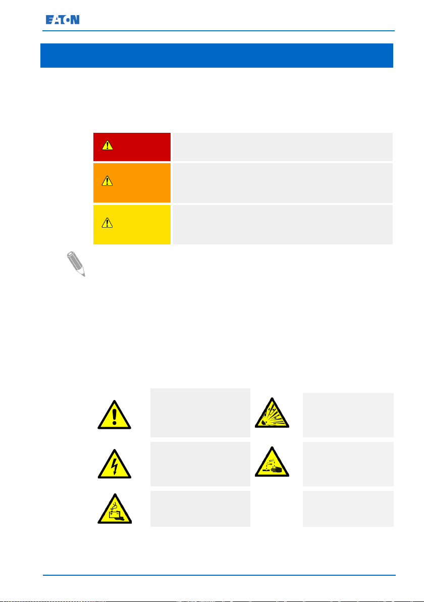
1.1 Safety-related signs
The following table explains the safety-related signs used in this
document.
DANGER
WARNING
CAUTION
NOTE: Notes are used to indicate important information and useful tips.
if not avoided, will result in serious injury or death.
which, if not avoided, could result in serious injury or
death, or damage to your machine.
if not avoided, could result in minor or moderate injury or
damage to your machine.
1.2 Safety symbols
1.2.1 Hazard symbols
These symbols indicate a hazardous situation or action. Symbols are
used to warn of situations, which may cause environmental damage and
personal injury.
General warning symbol
Explosion and fire
hazard
Electrical hazard
Battery hazard
© Eaton Corporation plc 2015. All rights reserved. Revision: 001
Corrosive hazard
Document ID: 614-01975-00
8 (133)
Eaton 93E UPS 15-80 kVA (380/400/415 V) Installation and Operation Manual
Bold type
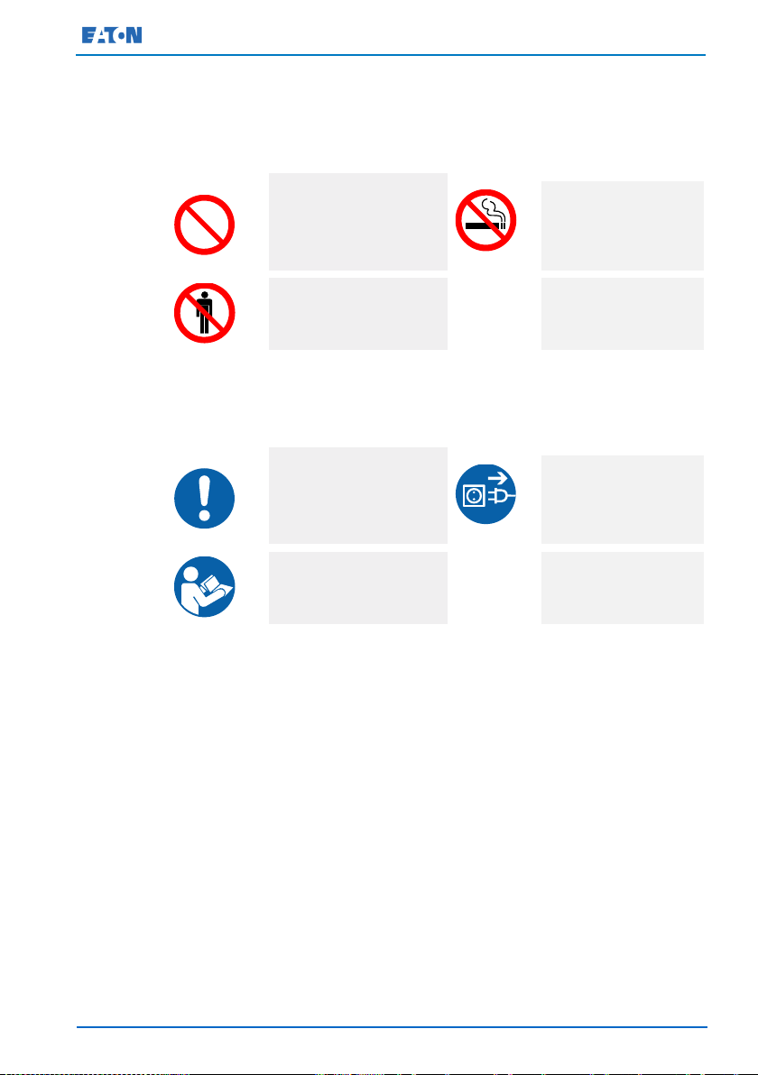
1.2.3 Prohibited action symbols
These symbols are used to indicate an action that should not be
taken.
General symbol for
prohibited action
Limited or restricted
access
No smoking
1.2.4 Mandatory action symbols
These symbols are used to indicate an action that must be taken.
General symbol for
mandatory action
Read the manual or
instructions
Disconnect from
power source
1.3 Conventions used in this document
This document uses the following type conventions:
•
procedures and menu options, or represents a command or option
that you type or enter at a prompt.
•
Italic type
• Screen type represents information that appears on the screen
or LCD.
highlights important concepts in discussions, key terms in
highlights notes and new terms when they are defined.
UPS
In this manual, the term
internal elements. The term
protection system - the UPS cabinet, the battery cabinet, and options or
accessories installed.
© Eaton Corporation plc 2015. All rights reserved. Revision: 001
refers only to the UPS cabinet and its
UPS system
refers to the entire power
Document ID: 614-01975-00
9 (133)

Eaton 93E UPS 15-80 kVA (380/400/415 V) Installation and Operation Manual
The term line-up-and-match refers to cabinets that are physically
attached to the UPS, and the wiring between them is internal. The term
standalone refers to cabinets that are not physically attached to the UPS,
and are wired with external contractor-supplied wiring.
© Eaton Corporation plc 2015. All rights reserved. Revision: 001
Document ID: 614-01975-00
10 (133)
Eaton 93E UPS 15-80 kVA (380/400/415 V) Installation and Operation Manual
.
.
.
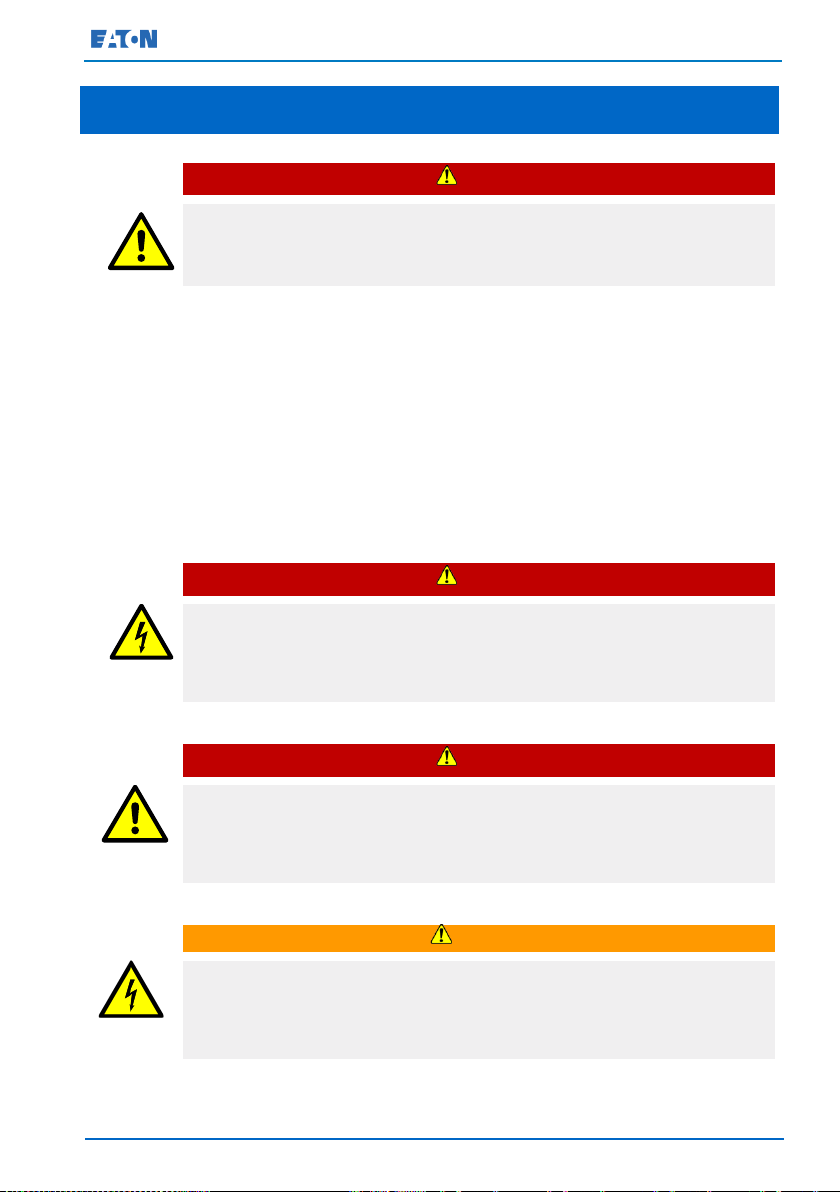
WARNING
2 Safety instructions
Important safety instructions!
Save these instructions!
This document contains important instructions that must be followed
during the installation, operation and maintenance of the UPS and the
batteries. Read all of the instructions before operating the equipment.
Keep this manual for future reference.
The UPS operates with mains, battery or bypass power. It contains
components that carry high currents and voltage. A properly installed
enclosure is earthed and IP20 rated against electrical shock and foreign
objects. However, the UPS is a sophisticated power system and only
qualified personnel are allowed to install and service it.
DANGER
DANGER
This UPS carries lethal voltages. All repairs and service must be
performed by authorized service personnel only. There are no userserviceable parts inside the UPS.
DANGER
Operations inside the UPS must be performed by a service engineer
from the manufacturer or from an agent authorized by the
manufacturer.
The UPS is powered by its own energy source (batteries). The output
terminals may carry live voltage even when the UPS is disconnected
from an AC source.
© Eaton Corporation plc 2015. All rights reserved. Revision: 001
Document ID: 614-01975-00
11 (133)

Eaton 93E UPS 15-80 kVA (380/400/415 V) Installation and Operation Manual
WARNING
To reduce the risk of fire or electric shock, install the UPS in a
temperature and humidity controlled, indoor environment that is free of
conductive contaminants. The ambient temperature must not exceed
40 °C (104 °F). Do not operate near water or excessive humidity (95%
maximum). The system is not intended for outdoor use.
As a result of the connected loads, high leakage current is possible.
Connection to earth ground is required for safety and proper product
operation. Do not check UPS operation by any action that includes
removal of the earth (ground) connection.
Before you start any installation or service work, make sure that all AC
and DC power sources are disconnected. Power may come from
multiple sources.
When undertaking installation or service work, ensure system
grounding continuity.
In a parallel system, the output terminals may be energized even when
the UPS is turned off.
Batteries can present a risk of electrical shock or burn from high short
circuit current. Always observe the following precautions when
working with batteries:
1) Remove watches, rings, or other metal objects.
2) Use tools with proper insulation.
3) Do not lay tools or metal parts on top of batteries.
4) Wear rubber gloves and boots.
Electric energy hazard. Do not attempt to alter any battery cabling or
connectors. Attempting to alter cabling can cause injury.
Do not open or mutilate batteries. Released electrolyte may be toxic
and is harmful to the skin and eyes.
The UPS may be connected to TN and TT power distribution systems.
The UPS unit is not suitable for IT (Isolated neutral or impedanceearthed neutral) or corner-earthed power distribution systems.
IMPORTANT: The battery may consist of multiple parallel strings.
Make sure that you disconnect all strings before installation.
© Eaton Corporation plc 2015. All rights reserved. Revision: 001
Document ID: 614-01975-00
12 (133)

Eaton 93E UPS 15-80 kVA (380/400/415 V) Installation and Operation Manual
CAUTION
Only qualified service personnel knowledgeable of the UPS and battery
systems and the required precautions are allowed to perform
installation or service work on batteries. Keep unauthorized personnel
away from the equipment. Before you install or replace equipment,
consider all the warnings, cautions, and notes concerning appropriate
handling. Before you connect or disconnect batteries, make sure
batteries are not being charged or discharged.
See the installation instructions before you connect the UPS to the
supply.
Make sure that your replacement batteries are of the same number
and type as the battery that was originally installed in the UPS.
Replacing the battery with an incorrect type causes a risk of explosion.
This UPS uses floating battery circuit which must not be grounded.
Dispose of batteries according to your local disposal requirements. Do
not dispose of batteries in a fire. When exposed to flame, batteries
may explode.
To ensure proper cooling airflow and to protect personnel from
dangerous voltages inside the unit, keep the UPS door closed and the
front panels installed.
Do not install or operate the UPS system close to gas or electric heat
sources.
Keep the operating environment within the parameters stated in this
document. Keep the surroundings of the UPS uncluttered, clean, and
free from excess moisture.
Observe all DANGER, CAUTION, and WARNING notices affixed to the
inside and outside of the equipment.
© Eaton Corporation plc 2015. All rights reserved. Revision: 001
Document ID: 614-01975-00
13 (133)
Eaton 93E UPS 15-80 kVA (380/400/415 V) Installation and Operation Manual
2.1 Audience
The intended audience of this document is as follows:
• People who plan and perform the installation of the UPS
• People who use the UPS
This document provides guidelines for how to check the UPS delivery
and how to install and operate the UPS.
The reader is expected to know the fundamentals of electricity, cabling,
electrical components and electrical schematic symbols. This document
is written for a global reader.
CAUTION
Read this document before you start to operate or perform work on
the UPS.
2.2 CE marking
The product has a CE marking in compliance with the following
European directives:
• LVD Directive (Safety) 2006/95/EC
• RoHS Directive 2011/65/EU
• EMC Directive 2004/108/EC
CAUTION
This is a product for commercial and industrial application in the
second environment. Installation restrictions or additional measures
may be needed to prevent disturbances.
2.3 User precautions
The only permitted user operations are as follows:
• Startup and shutdown of the UPS, excluding the commissioning
startup.
• Use of the LCD control panel and the Maintenance Bypass Switch
(MBS).
• Use of optional connectivity modules and their software.
© Eaton Corporation plc 2015. All rights reserved. Revision: 001
Document ID: 614-01975-00
14 (133)

Eaton 93E UPS 15-80 kVA (380/400/415 V) Installation and Operation Manual
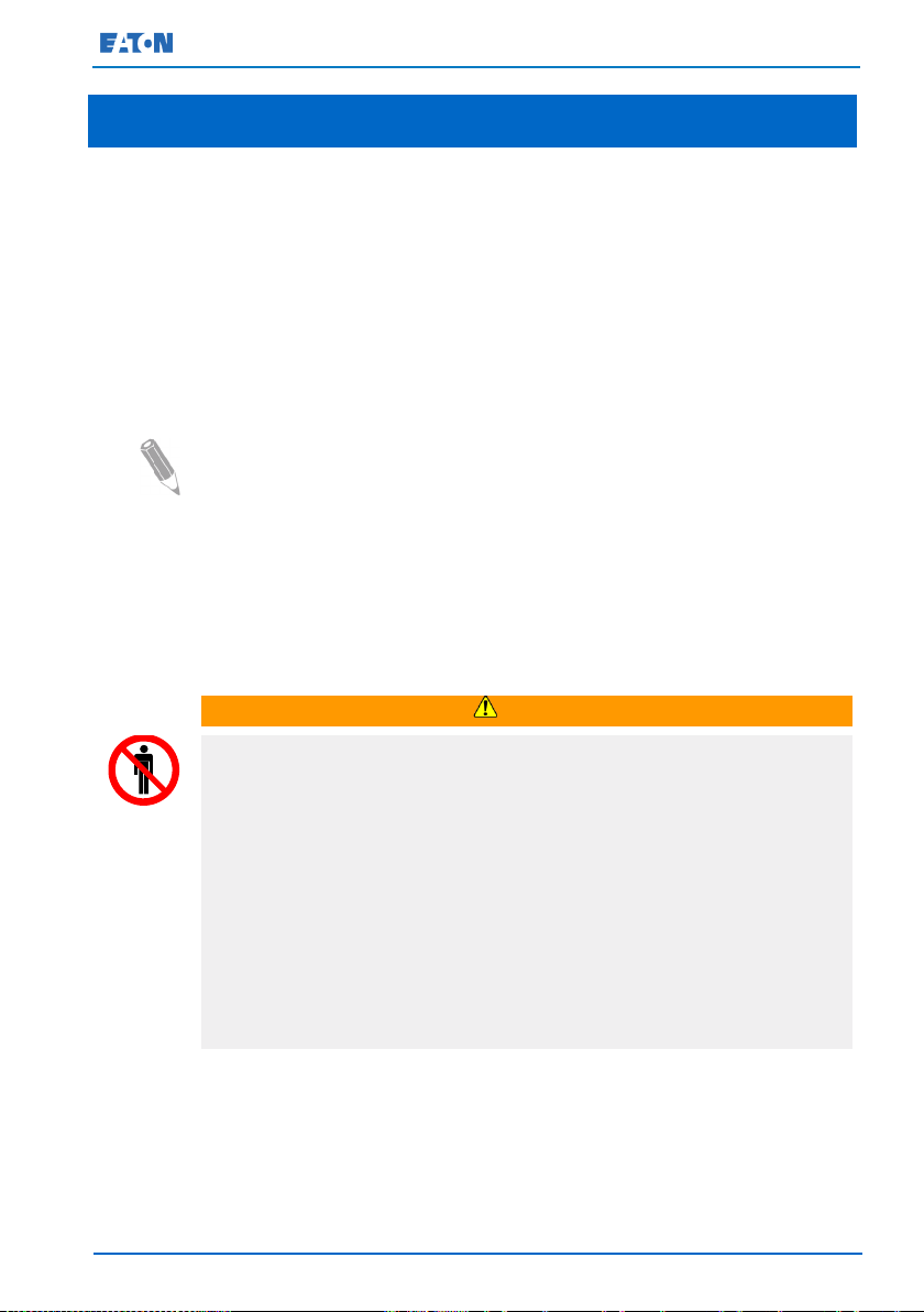
Follow the precautions and only perform the described operations. Any
deviation from the instructions can be dangerous to the user or cause
accidental load loss.
.
DANGER
Do not open any other screws in the unit than those holding the cover
plates of the MiniSlots and the MBS locking plate. Failure to recognize
the electrical hazards can prove fatal.
2.4 Environment
The UPS must be installed according to the recommendations in this
document. Never install the UPS in an airtight room, in the presence of
flammable gases, or in an environment exceeding the specifications.
Ensure sufficient amount of ventilation air flow preferably by natural
ventilation. Otherwise, forced (artificial) ventilation must be
implemented. Where forced ventilation is used, the air extracted from
the battery room must be exhausted to the atmosphere outside the
building.
The air inlet and outlet must be located at the best possible location to
create ideal conditions for the exchange of air, i.e. with:
• Openings on the opposite walls
• A minimum separation distance of 2 meters when openings on the
same wall
• It is recommended to locate the air inlet at the floor level and the air
outlet close to the ceiling level.
• It is recommended to create an airflow scheme for installation of
multiple UPSs.
• It is recommended to configure the installation layout with cold
aisles and hot aisles due to the UPS front-to-rear airflow protocol.
• For the free cooling applications, the cooling plan based on the
psychometric chart is highly recommended. The UPS specifications
must not be exceeded.
Excessive amount of dust in the operating environment of the UPS may
cause damage or lead to malfunction. Always protect the UPS from the
outside weather and sunshine. In order to maximize internal battery
© Eaton Corporation plc 2015. All rights reserved. Revision: 001
Document ID: 614-01975-00
15 (133)

Eaton 93E UPS 15-80 kVA (380/400/415 V) Installation and Operation Manual
service life time, the recommended operating temperature range is from
+20 ºC to +25 ºC. A temperature increase of 10 degrees reduces the life
approximately by 50%. Batteries need mandatory air change according
to the battery bank type, size and the charging current.
WARNING
During charge, float charge, heavy discharge, and overcharge,
hydrogen and oxygen gases are emitted from lead-acid and NiCd
batteries into the surrounding atmosphere. Explosive gas mixture may
be created if the hydrogen concentration exceeds 4% by volume in air.
Ensure the necessary air flow rate for the ventilation of the UPS
location.
NOTE: For more information about the battery room ventilation
requirements, including the calculation of the necessary air flow, see:
IEC 62485-2: Safety requirements for secondary batteries and battery
installations.
2.5 Using this manual
This manual describes how to install and operate the Eaton 93E 15-80
kVA. Read and understand the procedures described in this manual to
ensure trouble-free installation and operation. In particular, be thoroughly
familiar with the remote EPO procedure (see Section 7.3.13).
The information in this manual is divided into sections and chapters. The
system, options, and accessories being installed dictate which parts of
this manual should be read. At a minimum, Chapters 2 through 5 and
Chapter 7 should be examined.
Read through each procedure before beginning the procedure. Perform
only those procedures that apply to the UPS system being installed or
operated.
© Eaton Corporation plc 2015. All rights reserved. Revision: 001
Document ID: 614-01975-00
16 (133)
Eaton 93E UPS 15-80 kVA (380/400/415 V) Installation and Operation Manual
CAUTION: REFER TO OPERATOR'S
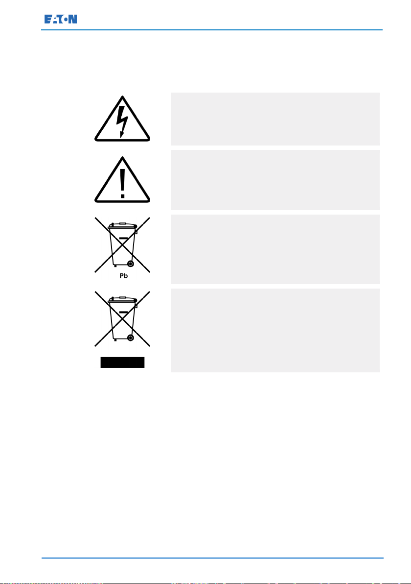
2.6 Symbols on the UPS and accessories
The following are examples of symbols used on the UPS or its
accessories. The symbols are used to alert you of important information.
RISK OF ELECTRIC SHOCK
Indicates that a risk of electric shock is present and the
associated warning should be observed.
MANUAL
Refer to your operator's manual for additional
information, such as important operating and
maintenance instructions.
This symbol indicates that you may not discard the UPS
or the UPS batteries in the trash. This product involves
sealed, lead-acid batteries and they must be disposed of
properly. For more information, contact your local
recycling / reuse or hazardous waste center.
2.7 For more information
Address any inquiries about the UPS and the battery cabinet to the local
office or an agent authorized by the manufacturer. Quote the type code
and the serial number of the equipment.
Call your local service representative if you need assistance with any of
the following:
• Scheduling initial startup
• Regional locations and telephone numbers
• A question about any of the information in this manual
© Eaton Corporation plc 2015. All rights reserved. Revision: 001
• A question that this manual does not answer
This symbol indicates that you must not discard waste
electrical or electronic equipment (WEEE) in the trash.
For proper disposal, contact your local recycling / reuse
or hazardous waste center.
Document ID: 614-01975-00
17 (133)

Eaton 93E UPS 15-80 kVA (380/400/415 V) Installation and Operation Manual
Refer to the External Battery Cabinet Installation Manual for the
following additional information:
• Installation instructions, including site preparation, planning for
installation, cabling and safety information, and detailed illustrations
of cabinets with dimensional and connection point drawings
Visit www.eaton.eu or contact an Eaton service representative for
information on how to obtain copies of these manuals.
© Eaton Corporation plc 2015. All rights reserved. Revision: 001
Document ID: 614-01975-00
18 (133)

Eaton 93E UPS 15-80 kVA (380/400/415 V) Installation and Operation Manual
your
3 Introduction to Eaton UPS
The Eaton 93E 15-80 kVA uninterruptible power supply (UPS) is a true
online, continuous-duty, transformer-free, double-conversion, solid-state,
3-phase system that provides conditioned and uninterruptible AC power
to protect the loads connected to it from power failures.
The Eaton 93E 15-80 kVA online power protection system is used to
prevent loss of valuable electronic information, minimise equipment
downtime, and minimise the adverse effect on production equipment
due to unexpected power problems.
The Eaton 93E 15-80 kVA UPS continually monitors incoming electrical
power and removes the surges, spikes, sags, and other irregularities that
are inherent in commercial utility power. Working with a building's
electrical system, the UPS system supplies clean, consistent power that
sensitive electronic equipment requires for reliable operation. During
brownouts, blackouts, and other power anomalies, batteries provide
emergency power to safeguard operation of the load equipment.
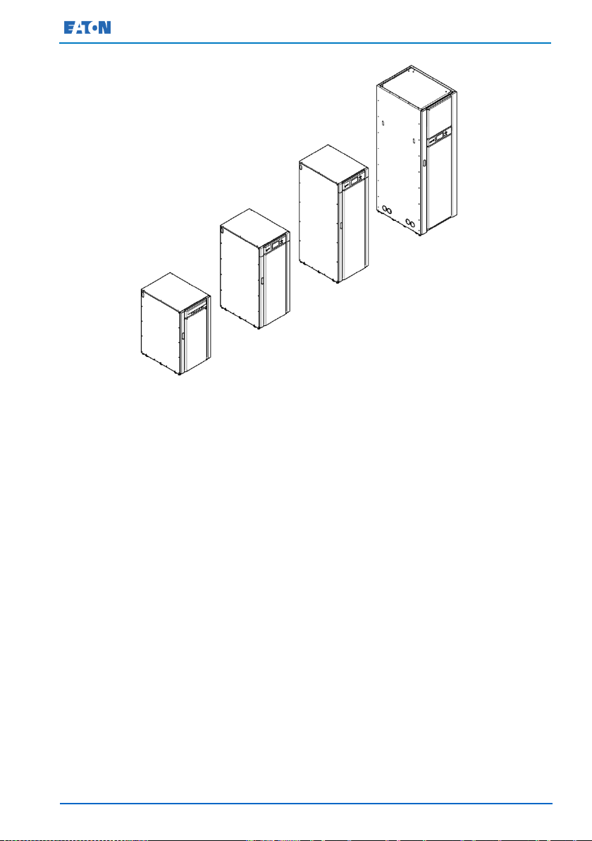
The UPS is housed in a single free-standing cabinet, with safety shields
behind the door for hazardous voltage protection.
This manual is for Eaton 93E series UPS, refer Section 10.1 for product
models.
Figure 1 shows the Eaton 93E 15-80 kVA UPS.
NOTE: Start-up and operational checks must be performed by a qualified
service personnel authorized by Eaton. If these instructions are not
followed, the warranty terms specified in Chapter 11 become void. This
service is offered as a part of the sales contract for the UPS. Contact
Eaton service representative in advance to reserve a preferred startup
date.
© Eaton Corporation plc 2015. All rights reserved. Revision: 001
Document ID: 614-01975-00
19 (133)
Eaton 93E UPS 15-80 kVA (380/400/415 V) Installation and Operation Manual
Figure 1. Eaton 93E UPS (15-80 kVA)
3.1 UPS standard features
The UPS has many standard features that provide cost-effective and
consistently reliable power protection. The descriptions in this section
provide a brief overview of the UPS standard features.
3.1.1 Installation features
Power cabling can be routed to the bottom or rear of the cabinet with
connections made to easily accessible terminals. Some models (Eaton
93E-15I / 93E-20I / 93E-30I / 93E-40I) provide rear-only cable access. For
more details, see Section 5.3.
3.1.2 Control panel
The control panel is located on the front of the UPS. It contains a liquid
crystal display (LCD) and push button switches to control the operation
of the UPS and to display the status of the UPS system. For more
information, see Chapter 7.
© Eaton Corporation plc 2015. All rights reserved. Revision: 001
Document ID: 614-01975-00
20 (133)

Eaton 93E UPS 15-80 kVA (380/400/415 V) Installation and Operation Manual
3.1.3 Communication interface
• Signal input monitoring
Up to 3 inputs in the UPS are available to connect the facility's
alarm system contacts. Some system configurations may limit the
number of inputs available. The UPS uses these inputs to monitor
the signal inputs in addition to the UPS status. For more
information, see Chapter 8.
• MiniSlot communication bays
2 communication bays are standard equipment. One to 2 optional
MiniSlot connectivity cards can be installed in the UPS module at
any time. MiniSlot cards are quickly installed at the front of the UPS
(behind the door) and are hot-pluggable. For more information, see
Chapter 8.
3.1.4 High-efficiency mode
The Eaton 93E Series UPS offers a high-efficiency (HE) normal mode
with double-conversion on demand. This mode allows the Eaton 93E
UPS to achieve 98% efficiency while still protecting the load. For
information on how to set the UPS to work in the high efficiency mode,
see Chapter 7.
3.1.5 Advanced Battery Management
A 3-stage charging system increases the battery service life by
optimizing the recharge time. It also protects the batteries from damage
due to high current charging and inverter ripple currents.
3.1.6 Maintenance bypass
The internal maintenance bypass for the 15-80 kVA models consists of
input, output, neutral and bypass input (dual feeds) switches used to
control the AC input to the UPS. The inverter output and the
maintenance bypass switch are used to partially isolate the UPS so that
a limited number of components can be serviced without interrupting
power to the critical systems.
3.2 Options and accessories
Contact your Eaton sales representative for more information about the
available options and accessories.
© Eaton Corporation plc 2015. All rights reserved. Revision: 001
Document ID: 614-01975-00
21 (133)

Eaton 93E UPS 15-80 kVA (380/400/415 V) Installation and Operation Manual
3.2.1 External battery cabinet
Battery backup protection is provided by equipping the UPS system with
up to 4 external battery cabinets (EBCs) containing sealed lead-acid,
maintenance-free batteries. An EBC is a single, free-standing cabinet
designed to be installed as a part of a UPS system, but may be installed
separate from the UPS cabinet.
3.2.2 Parallel system
A parallel UPS system with up to 4 UPSs can be installed to provide a
parallel capacity and/or redundant system. This load sharing system
provides more capacity than a single UPS, and can provide redundancy,
depending on the load and configuration. In addition, when one UPS is
taken out of service for maintenance or is not operating properly, a
redundant UPS continues to supply uninterrupted power to the critical
load. A Controller Area Network (CAN) bridge provides connectivity for
system metering and operational mode control. The parallel system
consists of 2 to 4 UPSs each with a parallel CAN bridge, and a tie cabinet
or system parallel module to act as a tie point and to control the output.
Module output breakers (MOBs) allow the output of a UPS to be
disconnected from other UPSs and the system load for maintenance and
service. Design considerations assume that each UPS has a module
output breaker (MOB). The breaker should also disconnect the neutral
for improved safety during maintenance.
The MOB must have at least one normally open (N.O.) and one normally
closed (N.C.) contact. These contacts must not share a common
terminal. The N.C. contact is connected to the corresponding UPS’s
input used for signal input. The N.O. contact is used to disconnect the
bypass pull-chain when the MOB is open. Figure 24 and Figure 25 show
the principles of paralleled UPS systems including MOBs and outputs
from UPSs.
3.2.3 Monitoring and communication
Optional MiniSlot cards support several alternative communication
interfaces, such as WEB/SNMP, RELAY / RS-232 and Modbus. For more
information on the monitoring and communication features, see Chapter
8.
© Eaton Corporation plc 2015. All rights reserved. Revision: 001
Document ID: 614-01975-00
22 (133)

Eaton 93E UPS 15-80 kVA (380/400/415 V) Installation and Operation Manual
3.2.4 Single feed
The Eaton 93E 15-80 kVA standard models come with dual feed,
requiring a separate feed for both rectifier and bypass input. Single feed
kits are provided with each unit for on-site installation.
3.3 Battery system
Depending on the UPS model, the battery system may be internal or
external. The battery system provides emergency short-term backup
power to safeguard the operation during brownouts, blackouts, and
other commercial power anomalies. The battery system is equipped
with lead-acid batteries.
3.4 Basic system configurations
The following basic UPS system configurations are possible (depending
on the model):
• UPS (internal battery).
• UPS with an external battery.
• UPS with external batteries and accessory cabinets
Up to 4 UPS's can be added in parallel for capacity or redundancy. The
UPS system configuration can be enhanced by adding optional
accessories, such as a remote Emergency Power-off (EPO) control or
MiniSlot communication cards.
© Eaton Corporation plc 2015. All rights reserved. Revision: 001
Document ID: 614-01975-00
23 (133)
Eaton 93E UPS 15-80 kVA (380/400/415 V) Installation and Operation Manual
4 UPS installation plan and unpacking
Use the following basic sequence of steps to install the UPS:
1. Create an installation plan for the UPS system.
2. Prepare your site for the UPS system.
3. Inspect and unpack the UPS cabinet.
4. Unload and install the UPS cabinet and wire the system.
5. Complete the installation checklist provided in Section 4.2.
6. Have authorized service personnel perform the preliminary
operational checks and startup.
NOTE: Startup and operational checks for parallel systems or
installations with accessory cabinets must be performed by an
authorized Eaton Customer Service Engineer, or the warranty terms
specified in the Warranty (see Chapter 11) become void. This service is
offered as a part of the sales contract for the UPS. Contact an Eaton
service representative in advance (usually a 2-week notice is required)
to reserve a preferred startup date.
WARNING
Only qualified technicians or electricians are allowed to carry out the
installation. The installation must also be done according to the
applicable safety standards.
Do not open any covers in the UPS. There are no user-serviceable
parts inside the UPS.
The UPS unit is not suitable for IT (Isolated neutral or impedanceearthed neutral) or corner-earthed power distribution systems.
During installation, make sure that no line input source can accidentally
be connected to the UPS.
© Eaton Corporation plc 2015. All rights reserved. Revision: 001
Document ID: 614-01975-00
24 (133)

Eaton 93E UPS 15-80 kVA (380/400/415 V) Installation and Operation Manual
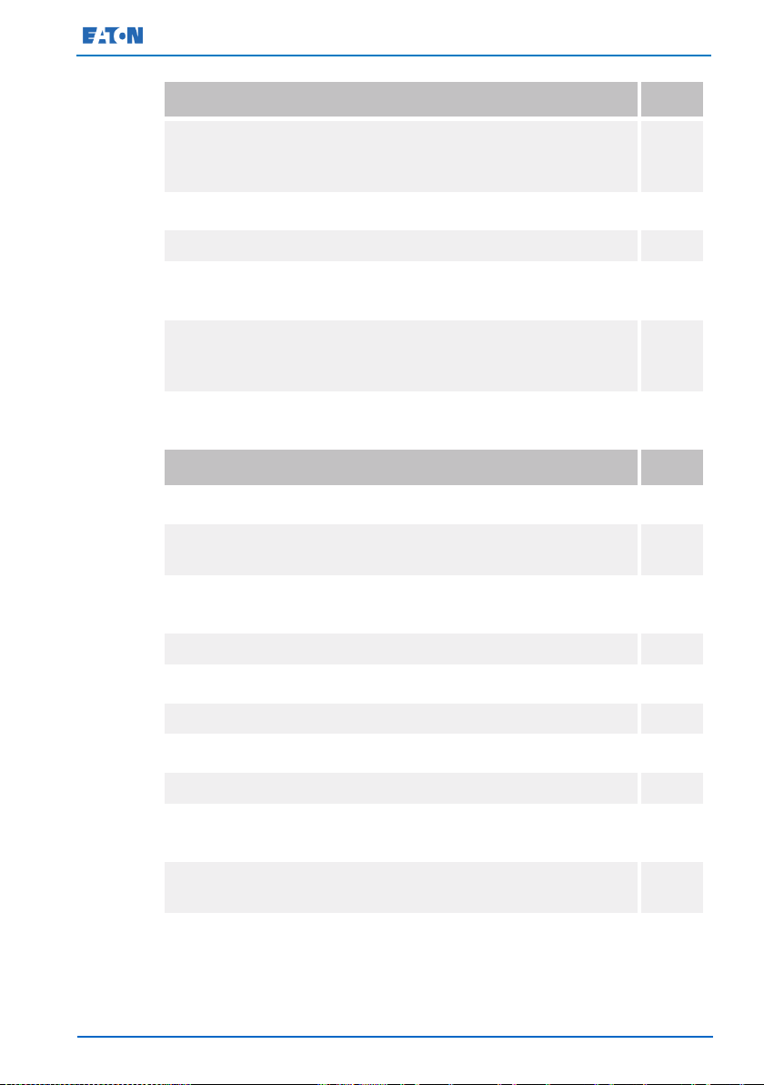
Action
Yes/No
All packing materials and restraints are removed from each cabinet.
The UPS cabinet is placed in its installed location.
All conduits and cables are properly routed to the UPS and any
A readily accessible disconnect device is installed between the UPS
All power cables are properly sized and terminated.
Neutral conductors are installed.
A ground conductor is properly installed.
(OPTIONAL) Signal inputs are wired appropriately.
(OPTIONAL) LAN drops are installed.
(OPTIONAL) LAN connections have been completed.
(OPTIONAL) The remote EPO device is mounted in its installed
(OPTIONAL) If a normally-closed remote EPO switch is used, a jumper
All terminal cover plates are installed.
(OPTIONAL) Accessories are mounted in their installed locations and
Air conditioning equipment is installed and operating correctly.
4.1 Creating an installation plan
Before you install the UPS system, read and understand how these
instructions apply to the system that you are going to install. Use the
procedures and illustrations in Section 4.3 and Chapter 5 to create a
logical plan for installing the system.
4.2 Installation checklist
ancillary cabinets.
input and utility power.
location and its cabling is terminated inside the UPS cabinet.
wire is connected between pins 3 and 4 on the remote EPO terminal
block.
their cabling is terminated inside the UPS cabinet.
© Eaton Corporation plc 2015. All rights reserved. Revision: 001
Document ID: 614-01975-00
25 (133)
Eaton 93E UPS 15-80 kVA (380/400/415 V) Installation and Operation Manual
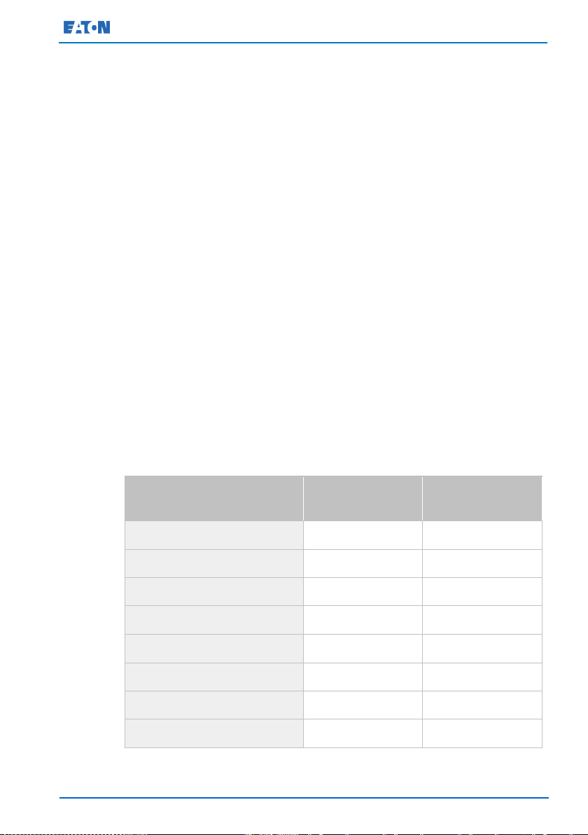
Action
Yes/No
The area around the installed UPS system is clean and dust-free (it is
There is adequate workspace around the UPS and other cabinets.
Adequate lighting is provided around all the UPS equipment.
A 230 VAC service outlet is located within 7.5 meters of the UPS
Startup and operational checks are performed by an authorized Eaton
Action
Yes/No
Each cabinet in the parallel system is placed in its installed location.
All conduits and cables are properly routed to the UPSs and to the
A readily accessible disconnect device is installed between the UPS
All power cables are properly sized and terminated.
Neutral conductors are installed between the cabinets as required.
Ground conductors are properly installed.
CAN wiring between the UPSs is properly installed.
Pull chain wiring between the UPSs is properly installed.
There is adequate workspace around the UPSs, parallel tie cabinet,
UPS outputs are separated by MOBs with dual auxiliary contacts for
Startup and operational checks are performed by an authorized Eaton
recommended that the UPS is installed on a level floor suitable for
computer or electronic equipment).
equipment.
Customer Service Engineer or by a qualified service personnel
authorized by Eaton.
4.2.1 Parallel system installation checklist
parallel tie cabinet.
input and utility power.
and other cabinets.
the control of the system.
Customer Service Engineer or by a qualified service personnel
authorized by Eaton.
© Eaton Corporation plc 2015. All rights reserved. Revision: 001
Document ID: 614-01975-00
26 (133)
Eaton 93E UPS 15-80 kVA (380/400/415 V) Installation and Operation Manual
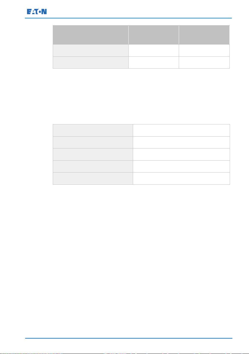
Mark
With package
kg (lb.)
Without package
kg (lb.)
Eaton 93E-15UI-N-64×9Ah-MBS
307 (677)
288 (635)
Eaton 93E-15UI-N-0-MBS
145 (320)
126 (278)
Eaton 93E-20I-N-64×9Ah-MBS
307 (677)
288 (635)
Eaton 93E-20I-N-0-MBS
145 (320)
126 (278)
Eaton 93E-30I-N-96×9Ah-MBS
405 (893)
386 (851)
Eaton 93E-30I-N-0-MBS
174 (384)
155 (342)
Eaton 93E-40I-N-128×9Ah-MBS
533 (1 175)
508 (1 120)
Eaton 93E-40I-N-0-MBS
216 (476)
194 (428)
4.3 Site preparations
For the UPS system to operate at peak efficiency, the installation site
must meet the environmental parameters outlined in these instructions.
If the UPS needs to be operated at an altitude higher than 1 000 m
(3 300 ft) contact your service representative for important information
about high altitude operation. The operating environment must meet the
height, clearance, and environmental requirements specified.
4.3.1 Environmental and installation considerations
The UPS system installation must meet the following guidelines:
• The system shall be installed indoors on a level floor suitable for
computer or electronic equipment.
• The system shall be installed in a temperature and humidity
controlled area in which the dew point cannot be reached and that
is free of conductive contaminants.
Failure to follow guidelines may void your warranty.
The UPS equipment operating environment must meet the weight
requirements shown in Table 1, and the size requirements shown in
Figure 2 through Figure 6. Dimensions are in millimeters (inches).
Table 1. UPS cabinet weights
© Eaton Corporation plc 2015. All rights reserved. Revision: 001
Document ID: 614-01975-00
27 (133)
Eaton 93E UPS 15-80 kVA (380/400/415 V) Installation and Operation Manual
Mark
With package
kg (lb.)
Without package
kg (lb.)
Eaton 93E-60-N-MBS
246 (542)
207 (456)
Eaton 93E-80-N-MBS
290 (639)
250 (551)
At the top of the cabinet
300 mm (12") working space
At the front of the cabinet
900 mm (36") working space
At the back of the cabinet
See Table 3.
At the right side of the cabinet
See Table 3.
At the left side of the cabinet
See Table 3.
The UPS cabinet uses forced air cooling to regulate internal component
temperature. Air inlets are in the front of the cabinet and outlets are at
the rear of the cabinet. Allow clearance in front of and behind the cabinet
for proper air circulation. The clearances required around the UPS
cabinet are shown in Table 2.
Table 2. UPS cabinet clearances
The basic environmental requirements for the operation of the UPS are
as follows:
• Ambient temperature range: from +0 to +40 °C (32–104 °F)
• Recommended operating range: from +20 to +25 °C (68–77 °F)
• Maximum relative humidity: 95%, non-condensing
© Eaton Corporation plc 2015. All rights reserved. Revision: 001
Document ID: 614-01975-00
28 (133)

Eaton 93E UPS 15-80 kVA (380/400/415 V) Installation and Operation Manual
15kVA/20kVA/30kVA/40kVA
60kVA/80kVA
Ambient
D1 (mm)
D2 (mm)
D1 (mm)
D2 (mm)
25oC
30oC
35oC
40oC
Table 3. Eaton 93E required clearance for paralleled adjacent UPS's or UPS and
adjacent PDU
≥120
≤50
≥150 ≥200
≥150
≤50
Notes:
• D1- clearance to the rear wall.
• D2- Eaton 93E required clearance for paralleled adjacent UPS's or
UPS and adjacent PDU. Parallel UPS should be as close as possible.
• Some models that feature rear connections also require additional
rear clearance to enable installation and connection.
CAUTION
If battery systems are located in the same room as the UPS, follow the
battery manufacturer's environmental requirements if they are more
stringent than the UPS requirements. Operating temperatures above
the recommended range result in decreased battery life and
performance, and may reduce or void the battery warranty.
It is required that ventilation of the UPS room is arranged. Sufficient
amount of air cooling is needed to keep the maximum room temperature
rise at the desired level:
• Temperature rise of +5 °C maximum requires the airflow of 600
• Temperature rise of +10 °C maximum requires the airflow of
An ambient temperature from +20 °C to +25 °C is recommended to
achieve a long life of the UPS and batteries. The cooling air that enters
the UPS must not exceed +40 °C. Avoid high ambient temperature,
© Eaton Corporation plc 2015. All rights reserved. Revision: 001
moisture, and humidity.
m³/h per 1 kW of losses.
300 m³/h per 1 kW of losses.
Document ID: 614-01975-00
29 (133)
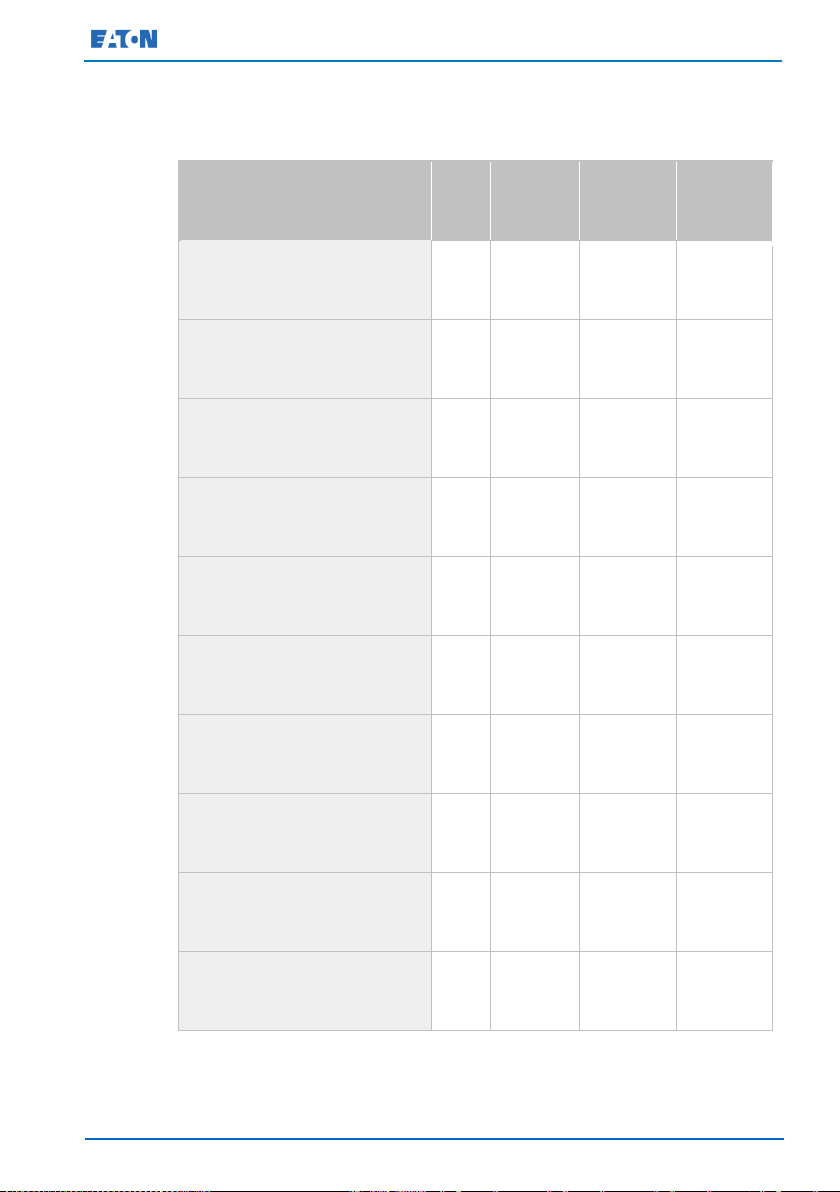
Eaton 93E UPS 15-80 kVA (380/400/415 V) Installation and Operation Manual
Model
kVA
Input /
output
voltage
Heat
rejection
(kW)
Heat
rejection
(BTU/hr)
Eaton 93E-15UI-N-64×9Ah-MBS
15
380/380
0.84
2 853
Eaton 93E-15UI-N-0-MBS
15
380/380
0.84
2 853
Eaton 93E-20I-N-64×9Ah-MBS
20
380/380
1.33
4 527
Eaton 93E-20I-N-0-MBS
20
380/380
1.33
4 527
Eaton 93E-30I-N-96×9Ah-MBS
30
380/380
1.84
6 293
Eaton 93E-30I-N-0-MBS
30
380/380
1.84
6 293
Eaton 93E-40I-N-128×9Ah-MBS
40
380/380
2.49
8 513
Eaton 93E-40I-N-0-MBS
40
380/380
2.49
8 513
Eaton 93E-60-N-MBS
60
380/380
3.57
12 181
Eaton 93E-80-N-MBS
80
380/380
4.57
15 593
The UPS ventilation requirements are shown in Table 4.
Table 4. Air conditioning or ventilation requirements during full load operation
400/400
415/415
400/400
415/415
400/400
415/415
400/400
415/415
400/400
415/415
© Eaton Corporation plc 2015. All rights reserved. Revision: 001
400/400
415/415
400/400
415/415
400/400
415/415
400/400
415/415
400/400
415/415
Document ID: 614-01975-00
30 (133)
Eaton 93E UPS 15-80 kVA (380/400/415 V) Installation and Operation Manual
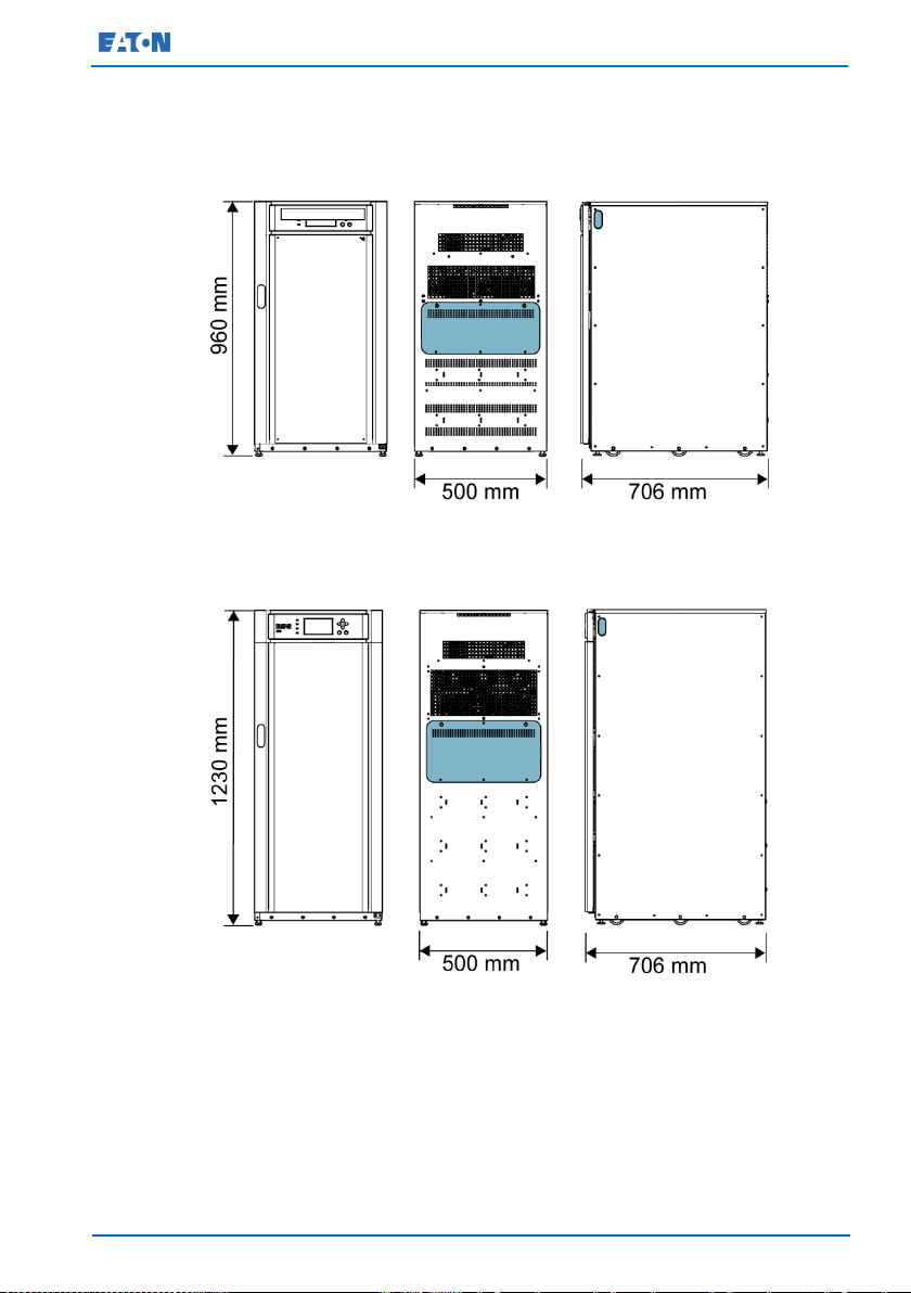
Figure 2, Figure 3, Figure 4, Figure 5 and Figure 6 illustrate the UPS
cabinet dimensions. The dimensions are in millimeters. Cable conduit
inlets are illustrated with highlight.
Figure 2. UPS cabinet dimensions (Eaton 93E 15-20 kVA front, rear and right side
views)
Figure 3. UPS cabinet dimensions (Eaton 93E 30 kVA front, rear and right side
views)
© Eaton Corporation plc 2015. All rights reserved. Revision: 001
Document ID: 614-01975-00
31 (133)
 Loading...