

Eaton 9395P-600/600, 9395P-600/550, 9395P-600/400, 9395P-600/500, 9395P-600/450 Installation And Operation Manual
...
Eaton PowerXpert 9395 High Performance (9395P-600) UPS
®
®
Installation and Operation Manual
For use with 380V, 400V, 415V, and 480V Single UPM (200–300 kVA),
Two UPM (400–550 kVA), and Plus 1 (400–600 kVA) UPS Models
Also for use with 600V Single UPM (200–275 kVA), Two UPM (300–550 kVA),
and Plus 1 (300 kW-550 kW)

IMPORTANT SAFETY INSTRUCTIONS
SAVE THESE INSTRUCTIONS
This manual contains important instructions that you should follow during installation and maintenance of the UPS and batteries. Please
read all instructions before operating the equipment and save this manual for future reference.
CONSIGNES DE SÉCURITÉ IMPORTANTES
CONSERVER CES INSTRUCTIONS
Ce manuel comporte des instructions importantes que vous êtes invité à suivre lors de toute procédure d'installation et de maintenance
des batteries et de l'onduleur. Veuillez consulter entièrement ces instructions avant de faire fonctionner l'équipement et conserver ce
manuel afin de pouvoir vous y reporter ultérieurement.
W A R N I N G
This is a product for restricted sales distribution to informed partners (EN/IEC 62040-2). Installation restrictions or additional measures
may be needed to prevent electromagnetic disturbances.
AVERTISSMENT
Les ventes et la distribution de ce produit sont limitées aux partenaires avisés (EN/CEI 62040-2). Des restrictions en matière d’installation
ou des mesures supplémentaires sont parfois nécessaires pour éviter les perturbations électromagnétiques.
Eaton and Power Xpert are registered trademarks and PredictPulse is a trademark of Eaton or its subsidiaries and affiliates. CA
Technologies is a registered trademark of CA, Inc. IBM and AS/400 are registered trademarks of International Business
Machines Corporation. Modbus is a registered trademark of Schneider Electric. National Electrical Code and NEC are registered
trademarks of National Fire Protection Association, Inc. All other trademarks are property of their respective companies.
ECopyright 2017 Eaton, Raleigh, NC, USA. All rights reserved. No part of this document may be reproduced in any way without
the express written approval of Eaton.

Table of Contents
1 Introduction 1-1............................................................................
1.1 Single UPM and Two UPM Configurations 1-2....................................................................
1.2 Single UPM Plus 1 and Two UPM Plus 1 Configurations 1-4..........................................................
1.3 UPS Standard Features 1-6.................................................................................
1.3.1 Installation Features 1-6..............................................................................
1.3.2 Control Panel 1-6....................................................................................
1.3.3 Customer Interface 1-6...............................................................................
1.3.4 Advanced Battery Management 1-6......................................................................
1.3.5 Power Management Software 1-6.......................................................................
1.4 Options and Accessories 1-7................................................................................
1.4.1 Integrated Battery Cabinets 1-7.........................................................................
1.4.2 Field Installed UPM 1-7...............................................................................
1.4.3 Sync Control 1-7....................................................................................
1.4.4 Single-Feed Kit 1-7..................................................................................
1.4.5 Distributed Bypass System 1-7..........................................................................
1.4.6 Input Output Module Configuration 1-8....................................................................
1.4.7 Continuous Static Switch 1-8...........................................................................
1.4.8 Inherent Redundancy 1-8..............................................................................
1.4.9 Energy Saver and High Alert Modes 1-8...................................................................
1.4.10 Variable Module Management System and High Alert Modes 1-9.................................................
1.4.11 Monitoring and Communication 1-9......................................................................
1.5 Battery System 1-10.......................................................................................
1.6 Using This Manual 1-11....................................................................................
1.7 Conventions Used in This Manual 1-11..........................................................................
1.8 Symbols, Controls, and Indicators 1-12..........................................................................
1.9 For More Information 1-13...................................................................................
1.10 Getting Help 1-13.........................................................................................
2 Safety Warnings 2-1........................................................................
Section I – Installation
3 UPS Installation Plan and Unpacking 3-1........................................................
3.1 Creating an Installation Plan 3-1.............................................................................
3.2 Preparing the Site 3-1.....................................................................................
3.2.1 Environmental Considerations 3-1........................................................................
3.2.2 Installation Considerations 3-2..........................................................................
3.2.3 Standard 380V, 400V, 415V, and 480V Model Configurations 3-5..................................................
3.2.4 600V Model Configurations 3-14.........................................................................
3.2.5 UPS System Power Wiring Preparation 3-19.................................................................
3.2.6 UPS System Interface Wiring Preparation 3-42................................................................
3.2.7 Distributed Bypass Power Wiring Preparation 3-44.............................................................
3.3 Inspecting and Unpacking the UPS Cabinets 3-44..................................................................
4 UPS System Installation 4-1..................................................................
4.1 Preliminary Installation Information 4-1........................................................................
4.2 Unloading the UPS Sections from the Pallet 4-1...................................................................
Eaton Power Xpert 9395P-600 (380V-600V) UPS Installation and Operation Manual S P-164000710 Rev 1 www.eaton.com/powerquality
i

TABLE OF CONTENTS
4.3 Mechanically Joining the Sections 4-5.........................................................................
4.4 Electrically Connecting the Sections (600V Models Only) 4-8..........................................................
4.4.1 Connecting the Ground Braid Cable 4-8....................................................................
4.4.2 Connecting Intercabinet CAN Cables and Connectors 4-10.......................................................
4.5 Field Installed UPM Installation 4-13...........................................................................
4.6 Battery System Installation 4-13..............................................................................
4.7 Distributed Bypass Tie Cabinet Installation 4-13...................................................................
4.8 Installing UPS External and Battery Power Wiring 4-14..............................................................
4.8.1 2-Hole Barrel Lug Terminations for Transformer Bus Bar Installation 4-14.............................................
4.8.2 External Power Wiring Installation 4-15.....................................................................
4.8.3 Battery Power Wiring 4-22..............................................................................
4.9 Installing Interface Connections 4-23...........................................................................
4.9.1 TB1, TB2, and TB3 Connections (Other than TB1 Battery Interface Connections) 4-24.....................................
4.9.2 TB1 Battery Interface Connections 4-29.....................................................................
4.9.3 X-Slot Connections 4-31...............................................................................
4.10 Installing a REPO Switch 4-32................................................................................
4.11 Installing Options, Accessories, and Distributed Bypass Control Wiring 4-36...............................................
4.12 Initial Startup 4-36........................................................................................
4.13 Completing the Installation Checklist 4-36.......................................................................
5 Installing Options and Accessories 5-1.........................................................
5.1 Installing an Optional Hot Sync CAN Bridge Card 5-2...............................................................
5.2 Installing Distributed Bypass Control Wiring 5-4..................................................................
5.3 Installing an Optional Remote Monitor Panel II 5-9.................................................................
5.4 Installing an Optional Relay Interface Module II 5-11................................................................
5.5 Installing an Optional Supervisory Contact Module II 5-13............................................................
5.6 Accessory Mounting Dimensions 5-15..........................................................................
Section II – Operation
6 Understanding UPS Operation 6-1.............................................................
6.1 UPS System Overview 6-1..................................................................................
6.2 Single UPS 6-2..........................................................................................
6.2.1 Modes 6-2........................................................................................
6.2.2 Online Mode 6-2....................................................................................
6.2.3 Energy Saver System (ESS) Mode 6-4.....................................................................
6.2.4 Variable Module Management System 6-4.................................................................
6.2.5 Bypass Mode 6-5...................................................................................
6.2.6 Battery Mode 6-6...................................................................................
6.3 Single UPS Unit System Oneline Configurations 6-8................................................................
6.4 Multiple UPS Distributed Bypass System 6-22.....................................................................
6.4.1 Multiple UPS Parallel System Modes 6-22...................................................................
6.4.2 Online Mode – Distributed Bypass 6-23....................................................................
6.4.3 Bypass Mode – Distributed Bypass 6-24....................................................................
6.4.4 Battery Mode – Distributed Bypass 6-26....................................................................
6.5 Multiple UPS Distributed Bypass System Oneline Configurations 6-27....................................................
7 UPS Operating Instructions 7-1................................................................
7.1 UPS Controls and Indicators 7-1..............................................................................
7.1.1 Control Panel 7-1....................................................................................
7.1.2 Circuit Breakers 7-2..................................................................................
7.2 Color Touchscreen Control Panel 7-2..........................................................................
ii
Eaton Power Xpert 9395P-600 (380V-600V) UPS Installation and Operation Manual S P-164000710 Rev 1 www.eaton.com/powerquality

TABLE OF CONTENTS
7.3 Using the Color Touchscreen Control Panel 7-2...................................................................
7.3.1 Status Indicators 7-3.................................................................................
7.3.2 Using the Touch Screen 7-3............................................................................
7.3.3 Using the Main Menu Buttons 7-6.......................................................................
7.3.4 Power Maps Screen (Online Mode) 7-7....................................................................
7.3.5 Power Maps Screen (Bypass Mode) 7-9....................................................................
7.3.6 Command Confirmation Pop-Up 7-9.......................................................................
7.3.7 Meters Summary Screen 7-10...........................................................................
7.3.8 Input Meters Screen 7-11..............................................................................
7.3.9 Input Meters Detail Screen 7-13..........................................................................
7.3.10 Battery Meters Screens 7-14............................................................................
7.3.11 System Events Main Screen 7-16.........................................................................
7.3.12 User Log 7-16.......................................................................................
7.3.13 System Status Screen and Controls 7-18....................................................................
7.3.14 Settings Screen 7-20..................................................................................
7.3.15 Configuration Options Screen 7-21........................................................................
7.3.16 Energy Advantage Architecture (EAA) Screen 7-21.............................................................
7.3.17 Statistics Basic Screen 7-23.............................................................................
7.3.18 ESS Comparison Screen 7-24............................................................................
7.3.19 UPS Module Map Screen 7-24...........................................................................
7.3.20 System Overview Screen 7-25...........................................................................
7.4 UPS Operation using the Color Touchscreen Control Panel 7-26........................................................
7.4.1 Starting the UPS in Online Mode 7-26......................................................................
7.4.2 Using the Remote Emergency Power-off Switch 7-27...........................................................
7.5 Multiple UPS Distributed Bypass Operation 7-29...................................................................
7.5.1 Starting the Distributed Bypass System in Online Mode 7-29.....................................................
7.5.2 Starting the Distributed Bypass System in Bypass Mode 7-30.....................................................
7.5.3 Starting a Single UPM 7-31.............................................................................
7.5.4 Single UPM Shutdown 7-32.............................................................................
7.5.5 Single UPM Restart 7-32...............................................................................
7.5.6 Single UPS Shutdown using Load Off 7-33...................................................................
7.5.7 Single UPS Shutdown using UPM Shutdown 7-33.............................................................
7.5.8 Single UPS Restart 7-35................................................................................
7.5.9 UPS and Critical Load Shutdown 7-36......................................................................
7.5.10 Charger Control 7-36
7.5.11
Using the UPS LOAD OFF Pushbutton 7-37...................................................................
..................................................................................
7.5.12 Using the UPS LOAD OFF Command 7-38....................................................................
7.5.13 Using the Remote Emergency Power-off Switch 7-39...........................................................
8 Communication 8-1.........................................................................
8.1 X-Slot Cards 8-1.........................................................................................
8.2 PredictPulse 8-2.........................................................................................
8.2.1 PredictPulse Features 8-2..............................................................................
8.2.2 Installing PredictPulse 8-3.............................................................................
8.3 Power Management Software 8-3............................................................................
8.4 Building Alarm Monitoring 8-4...............................................................................
8.5 General Purpose Relay Contact 8-4............................................................................
8.6 Remote Monitor Panel II 8-5................................................................................
8.7 Relay Interface Module II 8-7................................................................................
8.8 Supervisory Contact Module II 8-8............................................................................
Eaton Power Xpert 9395P-600 (380V-600V) UPS Installation and Operation Manual S P-164000710 Rev 1 www.eaton.com/powerquality
iii

TABLE OF CONTENTS
9 UPS Maintenance 9-1.......................................................................
9.1 Important Safety Instructions 9-1.............................................................................
9.2 Performing Preventive Maintenance 9-2........................................................................
9.2.1 DAILY Maintenance 9-2...............................................................................
9.2.2 MONTHLY Maintenance 9-2............................................................................
9.2.3 PERIODIC Maintenance 9-6............................................................................
9.2.4 ANNUAL Maintenance 9-6.............................................................................
9.2.5 BATTERY Maintenance 9-6............................................................................
9.3 Installing Batteries 9-7....................................................................................
9.4 Recycling the Used Battery or UPS 9-7.........................................................................
9.5 Maintenance Training 9-8..................................................................................
10 Product Specifications 10-1...................................................................
10.1 Model Numbers 10-1......................................................................................
10.2 Specifications 10-1........................................................................................
10.2.1 UPS Input 10-1......................................................................................
10.2.2 UPS Output 10-2.....................................................................................
10.2.3 UPS Environmental 10-2...............................................................................
Warranty W-1 .................................................................................
iv
Eaton Power Xpert 9395P-600 (380V-600V) UPS Installation and Operation Manual S P-164000710 Rev 1 www.eaton.com/powerquality

TABLE OF CONTENTS
List of Figures
Figure 1‐1. Standard Single UPM and Two UPM UPS Configurations (all except the 600V model) 1-2............................
Figure 1‐2. 600V Single UPM and Two UPM UPS Configurations (600V model only) 1-3.....................................
Figure 1‐3. Standard Single UPM and Two UPM, Plus 1 FI-UPM UPS Configurations (all except the 600V model) 1-4.................
Figure 1‐4. 600V Single UPM and Two UPM, Plus 1 FI-UPM UPS Configurations (600V only) 1-5...............................
Figure 3‐1. Standard Single UPM Configuration (Dimensions) 3-6.....................................................
Figure 3‐2. Standard Single UPM Configuration (Center of Gravity) 3-7..................................................
Figure 3‐3. Standard Single UPM Configuration, Plus 1 FI-UPM (Dimensions) 3-8..........................................
Figure 3‐4. Standard Single UPM Configuration, Plus 1 FI-UPM (Center of Gravity) 3-9.......................................
Figure 3‐5. Standard Two UPM Configuration (Dimensions) 3-10.......................................................
Figure 3‐6. Standard Two UPM Configuration (Center of Gravity) 3-11...................................................
Figure 3‐7. Standard Two UPM Configuration, Plus 1 FI-UPM (Dimensions) 3-12............................................
Figure 3‐8. Standard Two UPM Configuration, Plus 1 FI-UPM (Center of Gravity) 3-13........................................
Figure 3‐9. 600V Single UPM Configuration (Dimensions) 3-14........................................................
Figure 3‐10. 600V Single UPM Configuration, Plus 1 FI-UPM (Dimensions) 3-15............................................
Figure 3‐11. 600V Two UPM Configuration (Dimensions) 3-16.........................................................
Figure 3‐12. 600V Two UPM Configuration, Plus 1 FI-UPM (Dimensions) 3-17..............................................
Figure 3‐13. Side View Dimensions and Center of Gravity Measurements 3-18............................................
Figure 3‐14. Two UPM Configuration as Shipped on Pallet 3-47........................................................
Figure 4‐1. Removing the ISBM Section Left Side Shipping Bracket 4-3.................................................
Figure 4‐2. Removing the ISBM Section Right-Side Shipping Bracket 4-4................................................
Figure 4‐3. Section Joining 4-5..............................................................................
Figure 4‐4. ISBM and UPM Sections Joined 4-6..................................................................
Figure 4‐5. ISBM Section to UPM Section Joining Brackets 4-7.......................................................
Figure 4‐6. UPS Intercabinet Interface Harness Locations 4-10........................................................
Figure 4‐7. ISBM Section Intercabinet DC Power Terminal Locations 4-11................................................
Figure 4‐8. Pl1 Interface Board Location 4-12.....................................................................
Figure 4‐9. J39 Location on Pl1 Interface Board 4-12...............................................................
Figure 4‐10. Typical Bus Bar Barrel Lug Mounting – Hardware Assembly Sequence 4-14......................................
Figure 4‐11. ISBM and 2 UPM Section Debris Shields 4-15..........................................................
Figure 4‐12. ISBM Section Conduit and Wire Entry Locations 4-16......................................................
Figure 4‐13. Distributed Bypass Wire Length 4-18.................................................................
Figure 4‐14. ISBM Section Power Terminal Locations (380V, 400V, 415V, and 480V Models) 4-19...............................
Figure 4‐15. ISBM Section Power Terminal Locations (600V Models) 4-20................................................
Figure 4‐16. ISBM Section Power Terminal Detail - Section AA 4-21....................................................
Figure 4‐17. ISBM Section Power Terminal Detail BB – Common Battery 4-23.............................................
Figure 4‐18. ISBM Section Interface Terminal Locations 4-25.........................................................
Figure 4‐19. Interface Terminal Detail 4-27......................................................................
Figure 4‐20. Typical Alarm Relay Connection 4-27.................................................................
Figure 4‐21. Terminal Blocks TB1, TB2, and TB3 Connector Assignments 4-28.............................................
Figure 4‐22. Typical Battery Interface Connection – Common Battery System 4-30..........................................
Figure 4‐23. Typical Battery Interface Connection – Separate Battery System 4-30..........................................
Figure 4‐24. X-Slot Communication Bays 4-31....................................................................
Figure 4‐25. Remote EPO Switch Dimensions 4-32.................................................................
Figure 4‐26. REPO Switch 4-33...............................................................................
Figure 4‐27. Normally-Open REPO Switch Wiring 4-34..............................................................
Figure 4‐28. Normally‐Closed REPO Switch Wiring 4-35.............................................................
Figure 4‐29. Normally‐Closed and Normally‐Open REPO Switch Wiring
4-35...............................................
Eaton Power Xpert 9395P-600 (380V-600V) UPS Installation and Operation Manual S P-164000710 Rev 1 www.eaton.com/powerquality
v

TABLE OF CONTENTS
Figure 5‐1. Hot Sync CAN Bridge Card 5-2......................................................................
Figure 5‐2. Hot Sync CAN Bridge Card Connections 5-3............................................................
Figure 5‐3. Distributed Bypass System CAN and Pull-Chain Simplified Interface Wiring 5-5...................................
Figure 5‐4. Distributed Bypass System UPS CAN Wiring without MOBs 5-5..............................................
Figure 5‐5. Distributed Bypass Pull-Chain Wiring without MOBs 5-6...................................................
Figure 5‐6. Distributed Bypass Pull-Chain Wiring with MOBs 5-7......................................................
Figure 5‐7. Remote Monitor Panel II and Relay Interface Module II Terminal Locations 5-10....................................
Figure 5‐8. Remote Monitor Panel II, Relay Interface Module II, or Supervisory Contact Module II Wiring 5-10......................
Figure 5‐9. J1, J2, J3, and J4 15-Pin D-Sub Connectors 5-12..........................................................
Figure 5‐10. Supervisory Contact Module II Terminal Location 5-13.....................................................
Figure 5‐11. Supervisory Contact Module II TB2 5-14...............................................................
Figure 5‐12. Remote Monitor Panel II Dimensions 5-15..............................................................
Figure 5‐13. Relay Interface Module II Dimensions 5-16.............................................................
Figure 5‐14. Supervisory Contact Module II Dimensions 5-17.........................................................
Figure 6‐1. Main Elements of the UPS System 6-1................................................................
Figure 6‐2. Path of Current Through the UPS in Online Mode 6-3......................................................
Figure 6‐3. Path of Current Through the UPS in Bypass Mode 6-6......................................................
Figure 6‐4. Path of Current Through the UPS in Battery Mode 6-7.....................................................
Figure 6‐5. One UPM, Rectifier Feed, Battery System, Dual‐Feed Configuration, Continuous Static Switch 6-10......................
Figure 6‐6. One UPM, Common Rectifier Feed, Common Battery, Dual‐Feed Configuration, Continuous Static Switch, FI-UPM 6-11........
Figure 6‐7. One UPM, Common Rectifier Feed, Separate Battery, Dual‐Feed Configuration, Continuous Static Switch, FI-UPM 6-12........
Figure 6‐8. Two UPM, Common Rectifier Feed, Common Battery, Dual‐Feed Configuration, Continuous Static Switch 6-13..............
Figure 6‐9. Two UPM, Common Rectifier Feed, Separate Battery, Dual‐Feed Configuration, Continuous Static Switch 6-14..............
Figure 6‐10. Two UPM, Common Rectifier Feed, Common Battery, Dual‐Feed Configuration, Continuous Static Switch, FI-UPM 6-15.......
Figure 6‐11. Two UPM, Common Rectifier Feed, Separate Battery, Dual‐Feed Configuration, Continuous Static Switch, FI-UPM 6-16......
Figure 6‐12. Two UPM, Common Rectifier Feed, Common Battery, IOM Configuration 6-17....................................
Figure 6‐13. Two UPM, Common Rectifier Feed, Separate Battery, IOM Configuration 6-18....................................
Figure 6‐14. Three UPM Common Rectifier Feed, Common Battery, IOM Configuration 6-19....................................
Figure 6‐15. Three UPM Common Rectifier Feed, Separate Battery, IOM Configuration 6-20...................................
Figure 6‐16. Simplified Dual-Feed UPS with Maintenance Bypass Panel 6-21..............................................
Figure 6‐17. Path of Current through the UPSs in Online Mode – Distributed Bypass 6-24.....................................
Figure 6‐18. Path of Current through the UPSs in Bypass Mode – Distributed Bypass 6-25.....................................
Figure 6‐19. Path of Current through the UPSs in Battery Mode – Distributed Bypass 6-26.....................................
Figure 6‐20. Typical Distributed Bypass System – Continuous Static Switch, 1+1 and 2+0 Configurations 6-28......................
Figure 6‐21. Typical Distributed Bypass System – Continuous Static Switch, 2+1 and 3+0 Configurations 6-29......................
Figure 6‐22. Typical Distributed Bypass System – Continuous Static Switch, 3+1 and 4+0 Configurations 6-30......................
Figure 7‐1. 600 kW/kVA UPS Controls 7-1......................................................................
Figure 7‐2. UPS Color Touchscreen Control Panel (Typical) 7-2........................................................
Figure 7‐3. Parts of the Touch Screen 7-4......................................................................
Figure 7‐4. Sign In or Password Request Screen 7-5...............................................................
Figure 7‐5. Home Screen 7-6...............................................................................
Figure 7‐6. Main Menu and Power Maps Screen (Online Mode) 7-7....................................................
Figure 7‐7. Output kVA Screen from Home Screen 7-7.............................................................
Figure 7‐8. Average Efficiency Screen from Home Screen 7-8........................................................
Figure 7‐9. Consumption Screen from Home Screen 7-8............................................................
Figure 7‐10. Bypass Screen 7-9.............................................................................
Figure 7‐11. Typical Command Confirmation Screen (Charger Off)
Figure 7‐12. Meters Summary Screen 7-10......................................................................
Figure 7‐13. Input Meters Screen 7-11.........................................................................
Figure 7‐14. Bypass Meters Screen 7-11........................................................................
Figure 7‐15. Output Meters Screen 7-12........................................................................
7-9..................................................
vi
Eaton Power Xpert 9395P-600 (380V-600V) UPS Installation and Operation Manual S P-164000710 Rev 1 www.eaton.com/powerquality

TABLE OF CONTENTS
Figure 7‐16. Input Meters Detail Screen 7-13....................................................................
Figure 7‐17. Select Source Screen 7-13.........................................................................
Figure 7‐18. Battery Meters Screen 7-14........................................................................
Figure 7‐19. Battery Log Screen 7-14..........................................................................
Figure 7‐20. Battery Log Detail 7-15...........................................................................
Figure 7‐21. Battery Log Summary Screen 7-15...................................................................
Figure 7‐22. System Events Screen 7-16........................................................................
Figure 7‐23. User Log Screen 7-17............................................................................
Figure 7‐24. User Log Detail Screen 7-17.......................................................................
Figure 7‐25. System Status Screen 7-18........................................................................
Figure 7‐26. Module Controls Screen 7-18......................................................................
Figure 7‐27. Module Control Detail Screen 7-19...................................................................
Figure 7‐28. Online Mode Metering Method Option Screen 7-19.......................................................
Figure 7‐29. Bypass Mode Metering Method Option Screen 7-20......................................................
Figure 7‐30. Settings Screen 7-20.............................................................................
Figure 7‐31. Configuration Options Screen 7-21...................................................................
Figure 7‐32. Energy Advantage Architecture (EAA) Screen 7-21........................................................
Figure 7‐33. Disable ESS Screen 7-22..........................................................................
Figure 7‐34. High Alert Timer Screen 7-22.......................................................................
Figure 7‐35. Statistics Basic Screen 7-23........................................................................
Figure 7‐36. Statistics Data Detail Screen 7-23...................................................................
Figure 7‐37. ESS Comparison Screen 7-24.......................................................................
Figure 7‐38. UPS Module Map Screen 7-24......................................................................
Figure 7‐39. System Overview Screen 7-25......................................................................
Figure 7‐40. REPO Operation 7-28.............................................................................
Figure 8‐1. Optional X-Slot Cards 8-1.........................................................................
Figure 8‐2. Remote Monitor Panel II 8-5.......................................................................
Figure 8‐3. Relay Interface Module II 8-7.......................................................................
Figure 8‐4. Supervisory Contact Module II 8-8...................................................................
Figure 9‐1. ISBM Section Air Filter Locations – Continuous Static Switch 9-4.............................................
Figure 9‐2. FI-UPM Section Air Filter Locations 9-5................................................................
Eaton Power Xpert 9395P-600 (380V-600V) UPS Installation and Operation Manual S P-164000710 Rev 1 www.eaton.com/powerquality
vii

TABLE OF CONTENTS
This page intentionally left blank.
viii
Eaton Power Xpert 9395P-600 (380V-600V) UPS Installation and Operation Manual S P-164000710 Rev 1 www.eaton.com/powerquality

Chapter 1 Introduction
Figure
The Eaton® Power Xpert
®
9395P-600 uninterruptible power supply (UPS) is a true
online, continuous-duty, transformerless, double-conversion, solid-state, three-phase
system, providing conditioned and uninterruptible AC power to protect the
customer's load from power failures.
The 9395P-600 online power protection system is used to prevent loss of valuable
electronic information, minimize equipment downtime, and minimize the adverse
effect on production equipment due to unexpected power problems.
The 9395P-600 UPS continually monitors incoming electrical power and removes the
surges, spikes, sags, and other irregularities that are inherent in commercial utility
power. Working with a building's electrical system, the UPS system supplies clean,
consistent power that sensitive electronic equipment requires for reliable operation.
During brownouts, blackouts, and other power interruptions, batteries provide
emergency power to safeguard operation.
The UPS is available as a single unit or an optional multiple unit distributed bypass
system (see paragraph 1.4.5). The UPS is housed in free‐standing cabinets.
Four 9395P-600 UPS system configurations are available for 480V, 415V, 400V, and
380V models:
S two standard UPM configurations with one or two UPMs (see Figure 1‐1).
S two optional configurations with a field installed UPM (FI-UPM) added to the left of
a standard configuration (see Figure 1‐3).
NOTE The FI-UPM is not supplied as standard, but is available as an option to provide upgradability to a
maximum of 600 kVA. Adding the FI-UPM can also provide N+1 redundancy if the power requirements are
less than the single UPM rating. The FI-UPM matches the UPS in style and color.
Four 9395P-600 UPS system configurations are available for 600V models:
S two 600V UPM configurations with one or two UPMs (see Figure 1‐2).
S two optional 600V configurations with a field installed UPM (FI-UPM) added to the
left of a 600V configuration (see Figure 1‐4).
Eaton Power Xpert 9395P-600 (380V-600V) UPS Installation and Operation Manual S P-164000710 Rev 1 www.eaton.com/powerquality
1-1
INTRODUCTION
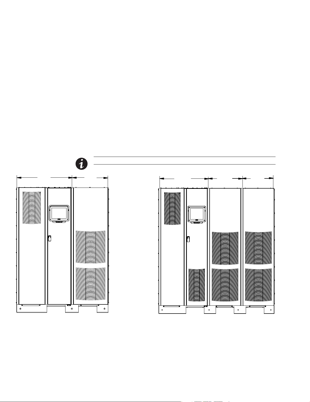
1.1 Single UPM and Two UPM Configurations
The Single UPM UPS 9395P-600 configuration has two sections:
S an ISBM section configured either as an integrated system bypass module (ISBM)
or an input output module (IOM) rated for a maximum of 600 kVA
S a UPM section with one UPM
The Two UPM UPS 9395P-600 configuration has two sections:
S an ISBM section configured either as an integrated system bypass module (ISBM)
or an input output module (IOM) rated for a maximum of 600 kVA
S a UPM section with two UPMs
For all models except the 600V, the two sections are shipped as a joined unit on the
same pallet (see Figure 1‐1).
For the 600V Single and Two UPM configurations, the ISBM section and the UPM
section are shipped separately on different pallets (see Figure 1‐2).
ISBM
NOTE Note that the ISBM section for the 600V models differs from the ISBM section for the other models.
UPM
ISBM
UPM
UPM
1-2
Standard ISBM and 1 x UPM
(380V, 400V, 415V, and 480V models)
Standard ISBM and 2 x UPM
(380V, 400V, 415V, and 480V models)
Figure 1‐1. Standard Single UPM and Two UPM UPS Configurations (all except the 600V model)
Eaton Power Xpert 9395P-600 (380V-600V) UPS Installation and Operation Manual S P-164000710 Rev 1 www.eaton.com/powerquality

INTRODUCTION
600V ISBM
600V ISBM and 1 x UPM
(600V models only)
UPM
600V ISBM
UPM
600V ISBM and 2 x UPM
(600V models)
Figure 1‐2. 600V Single UPM and Two UPM UPS Configurations (600V model only)
UPM
Eaton Power Xpert 9395P-600 (380V-600V) UPS Installation and Operation Manual S P-164000710 Rev 1 www.eaton.com/powerquality
1-3
INTRODUCTION
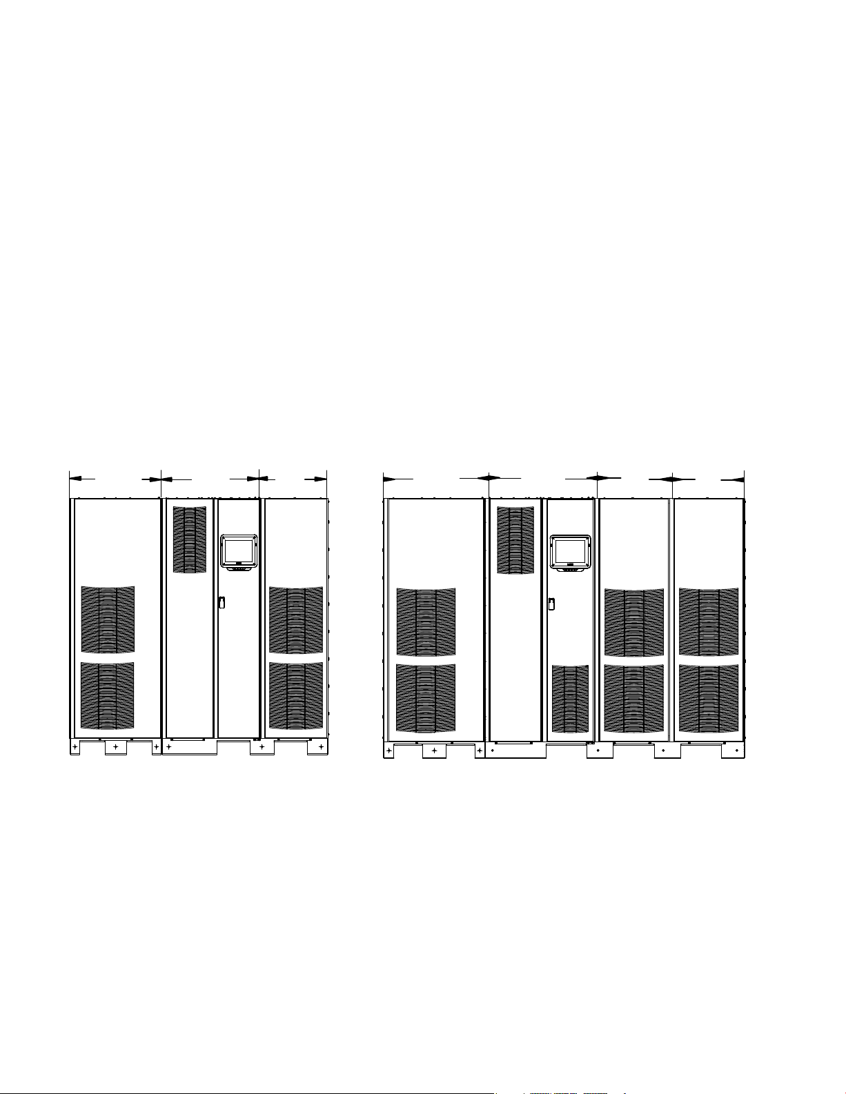
1.2 Single UPM Plus 1 and Two UPM Plus 1 Configurations
The optional Single UPM Plus 1 9395P-600 UPS configuration has three sections:
S an ISBM section configured either as an integrated system bypass module (ISBM)
or an input output module (IOM) rated for a maximum of 600 kVA
S a UPM section with one UPM
S one field-installed UPM (FI-UPM), which is field upgraded and provides N+1
redundancy for the basic configuration
The optional Two UPM UPS 9395P-600 configuration has three sections:
S an ISBM section configured either as an integrated system bypass module (ISBM)
or an input output module (IOM) rated for a maximum of 900 kVA
S a UPM section with two UPMs
S one field-installed UPM (FI-UPM), which is field upgraded and provides N+1
redundancy for the basic configuration
For Plus 1 field upgrades to all models, the FI-UPM is shipped separately and is added
later to the left of the existing configuration (see Figure 1‐3 and Figure 1‐4).
FI-UPM
Standard ISBM and 1 x UPM Section, Upgraded with
Plus 1 Field Installed FI-UPM
(380V, 400V, 415V, and 480V)
ISBM
UPM
Figure 1‐3. Standard Single UPM and Two UPM, Plus 1 FI-UPM UPS Configurations (all except the 600V model)
FI-UPM
Standard ISBM and 2 x UPM Section, Upgraded with
Plus 1 Field Installed FI-UPM
(380V, 400V, 415V, and 480V)
ISBM
UPM
UPM
1-4
Eaton Power Xpert 9395P-600 (380V-600V) UPS Installation and Operation Manual S P-164000710 Rev 1 www.eaton.com/powerquality
INTRODUCTION
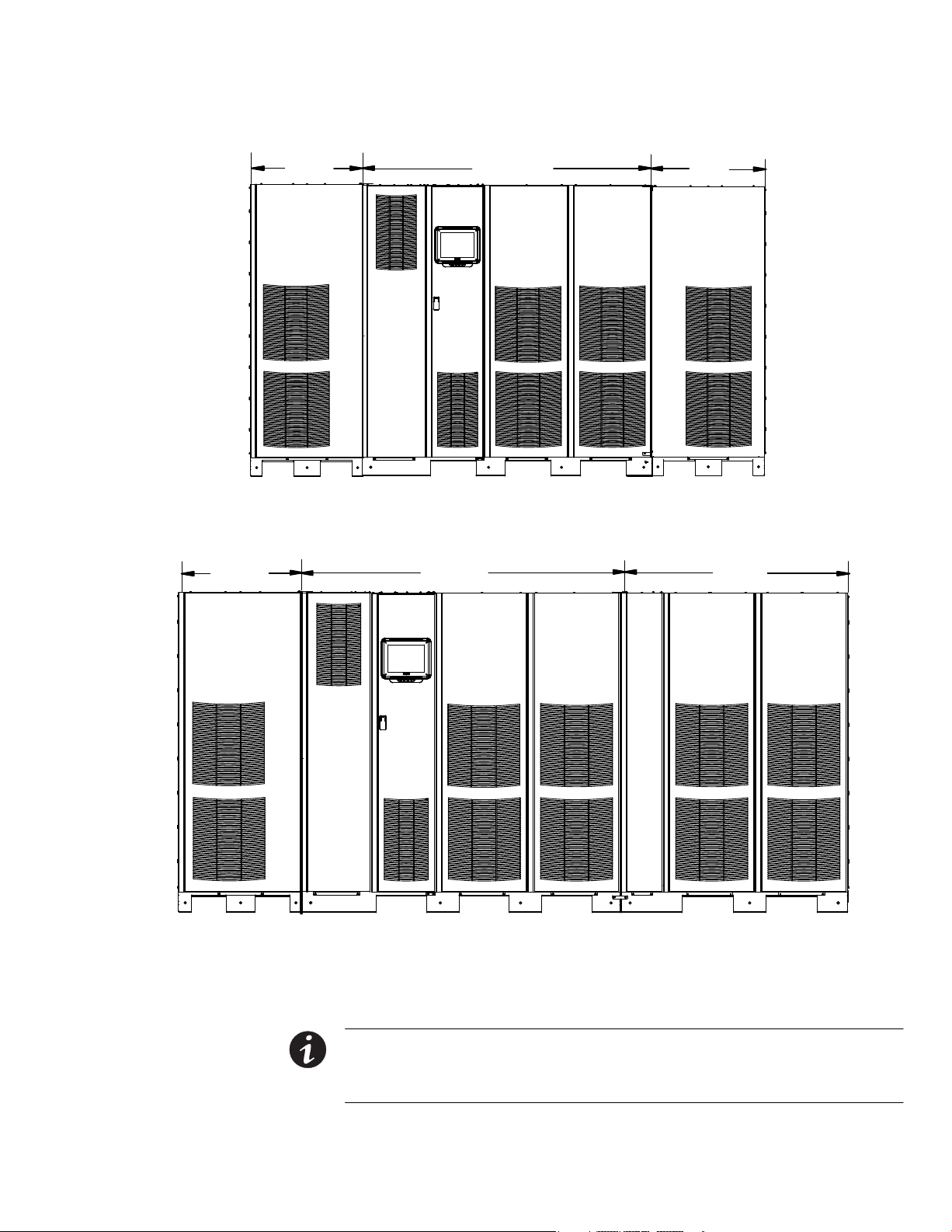
FI-UPM
FI-UPM
600V ISBM Section and 1 x UPM Section, Upgraded with Plus 1 Field Installed FI-UPM
(600V only)
600V ISBM
600V ISBM
UPM
UPMs
600V ISBM Section and 2 x UPM Section, Upgraded with Plus 1 Field Installed FI-UPM
(600V only)
Figure 1‐4. 600V Single UPM and Two UPM, Plus 1 FI-UPM UPS Configurations (600V only)
NOTE Startup and operational checks must be performed by an authorized Eaton Customer Service
Engineer, or the warranty terms specified on page W-1 become void. This service is offered as part of the
sales contract for the UPS. Contact an Eaton service representative in advance (usually a two-week notice is
required) to reserve a preferred startup date.
Eaton Power Xpert 9395P-600 (380V-600V) UPS Installation and Operation Manual S P-164000710 Rev 1 www.eaton.com/powerquality
1-5

INTRODUCTION
1.3 UPS Standard Features
The UPS has many standard features that provide cost‐effective and consistently
reliable power protection. The descriptions in this section provide a brief overview of
the UPS standard features.
1.3.1 Installation Features
Each UPS section is shipped separately. The sections are mechanically and electrically
joined at the installation site, and can be permanently bolted to the floor.
Power wiring can be routed through the top or bottom of the cabinet with
connections made to easily accessible terminals. Control wiring is routed through the
top of the cabinet and must be installed in accordance with Class 1 wiring methods.
1.3.2 Control Panel
The control panel, located on the front of the UPS is a 10-inch color touchscreen to
control the operation of the UPS and to display the status of the UPS system. See
Chapter 7, “UPS Operating Instructions,” for additional information.
1.3.3 Customer Interface
S Building Alarm Monitoring – Up to five inputs in the UPS are available to connect the
facility's alarm system contacts. Some system configurations may limit the
number of inputs available. The UPS uses these inputs to monitor the building
alarms in addition to the UPS status. See Chapter 8, “Communication,” for
additional information.
S Alarm Contact – One alarm contact is provided for connection to equipment at the
facility, such as a light, an audible alarm, or a computer terminal. The equipment
connected to this contact alerts you to a UPS alarm. See Chapter 8,
“Communication,” for additional information.
S X-Slot Communication Bays – Four communication bays are standard equipment.
One to four optional X-Slot
at any time. X-Slot cards are quickly installed at the front of the UPS and are
hot-pluggable. See Chapter 8, “Communication,” for additional information.
®
connectivity cards can be installed in the UPS module
1.3.4 Advanced Battery Management
A three-stage charging system increases battery service life by optimizing recharge
time, and protects batteries from damage due to high current charging and inverter
ripple currents. Charging at high currents can overheat and damage batteries.
1.3.5 Power Management Software
Intelligent Power Management and Intelligent Power Protector software are available
through Eaton support. See Chapter 8, “Communication,” for additional information.
1-6
Eaton Power Xpert 9395P-600 (380V-600V) UPS Installation and Operation Manual S P-164000710 Rev 1 www.eaton.com/powerquality

1.4 Options and Accessories
Contact an Eaton sales representative for information about the following options.
1.4.1 Integrated Battery Cabinets
Battery backup protection can be provided by equipping the UPS system with
9395P-600 battery cabinets containing sealed lead‐acid, maintenance‐free batteries.
The cabinets are designed for standalone installation and may be installed adjacent to
the UPS or in a separate location. The recommended installation location for adjacent
battery cabinets is on the right side of the UPS cabinet to allow for future expansion
using an external module.
Consult the .Eaton Power Xpert 9395 Integrated Battery Cabinet (Model 1085 and
1085HR) Installation Manual (P-164000580) for specifics on battery cabinet usage
with the 9395P-600.
1.4.2 Field Installed UPM
A Field Installed UPM (FI-UPM) provides redundancy for the 9395P-600. The FI-UPM
may be installed at any time in the future. The module cabinet is installed on the left
side of the ISBM section and is wired directly to the UPS. No input or output wiring
changes are needed for adding redundancy. Operation remains the same as the
original UPS.
INTRODUCTION
Refer to the Eaton Power Xpert 9395P UPS Field Installed UPM Mechanical
Installation Manual (P-164000503) for specifics on the FI-UPM usage with the
9395P-600.
1.4.3 Sync Control
An optional 9395P-600 Sync Control maintains the critical load outputs of two
separate single module 9395P-600 UPS systems in synchronization. This option
facilitates the uninterrupted transfer of the load from one load bus to another by
means of transfer switches. The Sync Control is housed in a wall‐mounted panel that
can be located between the UPS units for easy wiring.
Refer to the Eaton Power Xpert 9395P Sync Control Installation and Operation Manual
(P164000502) for specifics on sync control usage with the 9395P-600.
1.4.4 Single-Feed Kit
An optional kit is available for converting the dual-feed rectifier and bypass inputs to a
single-feed configuration. The kit consists of jumpers and bus bar extensions for each
phase, and the hardware required for installation.
Refer to the Eaton 9395/9395P UPS (1000-1200 kVA) Single-Feed Kit Installation
Instructions (P-164000610) manual for installation instructions.
1.4.5 Distributed Bypass System
There are two types of redundancy: UPS based (based on the number of UPSs) and
UPM based (based on the number of UPMs).
NOTE All UPSs in the distributed bypass system must contain the same number of UPMs. Mixed UPS kVA
ratings are not permitted.
Eaton Power Xpert 9395P-600 (380V-600V) UPS Installation and Operation Manual S P-164000710 Rev 1 www.eaton.com/powerquality
1-7

INTRODUCTION
A distributed bypass UPS system can be installed to provide a capacity and/or
redundant system. This load sharing system provides more capacity than a single
UPS, and can provide backup, depending on the load and configuration. In addition,
when one UPM is taken out of service for maintenance or is not operating properly, a
redundant UPM continues to supply uninterrupted power to the critical load. A Hot
Sync Controller Area Network (CAN) Bridge Card provides connectivity and
operational mode control.
The tie cabinet is provided by the customer and must contain Module Output
Breakers (MOBs) with dual auxiliary contacts for control of the system. Without dual
auxiliary MOBs, UPMs are not allowed to go to bypass individually during servicing.
All UPMs will go to bypass instead of just the UPM needing service, decreasing
critical load protection. With dual auxiliary MOBs, one UPM can be bypassed while
the remaining UPMs support the load as long as the remaining UPMs have the
capacity to do so.
1.4.6 Input Output Module Configuration
The UPS can be supplied in an Input Output Module (IOM) configuration without the
bypass input connections, the static switch, and the backfeed protection contactor.
This configuration is primarily used in multiple UPS parallel systems that do not need
a bypass for each UPS and use a separate System Bypass Module (SBM) to provide
system bypass capabilities.
1.4.7 Continuous Static Switch
A continuous static switch is used to provide transfer of the load from the inverter to
the bypass source in the event the inverter become unavailable.
1.4.8 Inherent Redundancy
To deliver greater reliability, the 9395P-600 UPS can be configured by an authorized
Eaton Customer Service Engineer for inherent redundancy. When configured, the
UPS automatically becomes redundant if the load is at or below the capacity of the
UPMs minus the capacity of one UPM. Under normal conditions the UPMs in the
UPS share the load equally. If one or more UPMs becomes unavailable and the load is
at or below the capacity of remaining UPMs, the remaining UPMs supply the load
instead of transferring to bypass.
If the capacity of the UPMs falls below the redundancy level or the load increases
above redundancy level, but is still able to maintain the load, a loss of redundancy
alarm is sounded. If the load exceeds the capacity of remaining UPMs, the UPS
transfers to bypass.
1.4.9 Energy Saver and High Alert Modes
NOTE Energy Saver System mode requires the UPS to be factory built with a Continuous Static Switch
(CSS).
NOTE The Variable Module Management System and Energy Saver System modes are mutually exclusive.
1-8
As a subset of Normal mode, Energy Saver mode maximizes efficiency by eliminating
unnecessary power conversion when the commercial power source is within
acceptable voltage and frequency limits. In this mode, the UPS is actively monitoring
the critical bus and instantly and seamlessly transitions to double-conversion mode
(inverter online) if a commercial electrical power brownout, blackout, overvoltage,
undervoltage, or out‐of‐tolerance frequency condition occurs.
Eaton Power Xpert 9395P-600 (380V-600V) UPS Installation and Operation Manual S P-164000710 Rev 1 www.eaton.com/powerquality

INTRODUCTION
In High Alert mode the unit transfers from Energy Saver mode to double-conversion
mode or if in double-conversion mode remains in double-conversion mode for a
default time period of one hour. High Alert mode allows the user to place the unit in
double-conversion mode when outside conditions could cause a power disturbance.
At the completion of the time period, the unit defaults back to Energy Saver mode. If
the High Alert command is received during the time period, the timer will be
restarted.
1.4.10 Variable Module Management System and High Alert Modes
NOTE Variable Module Management System and Energy Saver modes are mutually exclusive.
Variable Module Management (VMMS) maintains UPM redundancy and achieves
higher efficiencies by intelligently controlling the UPM’s load level. The efficiency
rating for each UPM is highest when loads are greater than 50% of the system rating.
Therefore, shifting the load to fewer UPMs can achieve higher efficiencies when the
UPS load is lighter.
In VMMS mode, the UPS is actively monitoring the critical bus and UPMs are
available to assume load in less then 2 ms to respond to load changes.
The VMMS feature has three configurable modes of operation: Online mode, Online
mode with VMMS, and High Alert mode. All modes are selectable from the front
panel.
VMMS mode supports both distributed bypass and SBM parallel configurations.
In High Alert mode, all idle UPMs go online for one hour. At the completion of the
hour, the UPS defaults back to VMMS mode. If the high alert command is received
during the one hour, the one hour timer will be restarted.
1.4.11 Monitoring and Communication
The UPS system can be further enhanced by adding optional accessories such as a
Remote Emergency Power-off (REPO) control, RMP II, SCM II, RIM II, or X-Slot
communication cards. See Chapter 5 , “Options,” for additional information.
Eaton Power Xpert 9395P-600 (380V-600V) UPS Installation and Operation Manual S P-164000710 Rev 1 www.eaton.com/powerquality
1-9

INTRODUCTION
S Remote Monitor Panel II (RMP II) – An optional RMP II contains backlit status
indicators and a local horn, allowing monitoring of the operational status and alarm
condition of the UPS from virtually any location within the facility.
S Relay Interface Module II (RIM II) – An optional RIM II uses relay contact closures to
indicate the UPS operating status and alarm condition.
S Supervisory Contact Module II (SCM II) – An optional SCM II establishes an interface
between the UPS system equipment and the customer's monitor.
S X-Slot Card – Optional X-Slot cards support several protocols, such as SNMP, HTTP,
®
IBM
AS/400®, and Modbus®.
S PredictPulset Remote Monitoring and Management Service – PredictPulse is a
subscription monitoring and management service from Eaton that collects and
analyzes data from connected power infrastructure devices, providing us with the
insight needed to make recommendations and take action on your behalf. It’s also
powered by CA Technologies, bringing together the best in hardware and
software. Like a second set of eyes on your power infrastructure, PredictPulse
provides 24/7 remote monitoring of alarms and system performance (load,
temperature/humidity, battery health, energy savings and service level) to reduce
downtime risk and expedite repairs. PredictPulse also shares real-time status and
trend information via an online dashboard and smartphone mobile app (Apple and
Android), giving subscribers insights about past and current performance, a list of
all active alarms, and asset management data (i.e., battery date codes, last and
next scheduled service dates, firmware versions). The service notifies customers
of critical alarms, supports remote diagnostics, and facilitates smart dispatch of
technicians. PredictPulse requires a Power Xpert Gateway UPS (PXGX)
connectivity card in an X-Slot communication bay and an Environmental Monitoring
Probe (EMP) for battery temperature/humidity monitoring.
1.5 Battery System
See Chapter 8, “Communication,” for additional information on monitoring and
communication features.
Although not provided with the UPS, a battery system is required to provide
emergency short-term backup power to safeguard operation during brownouts,
blackouts, and other power interruptions. The battery system should be equipped
with lead‐acid batteries. An external battery disconnect switch must be used.
The UPMs may be powered with either a common or separate battery system. In a
common battery system, single and multiple UPMs are powered from one common
battery source. In a separate battery system, multiple UPMs are each powered from
separate battery sources.
UPSs in distributed bypass and parallel systems must use a separate battery system.
Consult the Eaton Power Xpert 9395 Integrated Battery Cabinet (Model 1085 and
1085HR) Installation Manual (P-164000580) for specifics on battery cabinet usage
with the 9395P-600.
A supplemental 48 Vdc shunt trip signal for the battery disconnect device is provided
by the UPS, but is not required for normal operation.
NOTE The 9395P-600 system can trip a maximum of six battery cabinets total. This applies to both the
1085 standard and High Rate series batteries. If more than six battery cabinets in total are needed in a
separate UPM battery configuration, DO NOT hook up the shunt trips.
1-10
Eaton Power Xpert 9395P-600 (380V-600V) UPS Installation and Operation Manual S P-164000710 Rev 1 www.eaton.com/powerquality

1.6 Using This Manual
This manual describes how to install and operate the Eaton 9395P-600/450 UPS.
Read and understand the procedures described in this manual to ensure trouble-free
installation and operation. In particular, be thoroughly familiar with the REPO
procedure (see paragraph 7.4.2).
The information in this manual is divided into sections and chapters. The system,
options, and accessories being installed dictate which parts of this manual should be
read. At a minimum, Chapters 1 through 4 and Chapter 7 should be examined.
Read through each procedure before beginning the procedure. Perform only those
procedures that apply to the UPS system being installed or operated.
1.7 Conventions Used in This Manual
This manual uses these type conventions:
S Bold type highlights important concepts in discussions, key terms in procedures,
and menu options, or represents a command or option that you type or enter at a
prompt.
S Italic type highlights notes and new terms where they are defined.
S Screen type represents information that appears on the screen or LCD.
INTRODUCTION
Icon Description
Information notes call attention to important features or instructions.
[Keys] Brackets are used when referring to a specific key, such as [Enter] or [Ctrl].
In this manual, the term UPS refers only to the UPS cabinet and its internal elements.
The term UPS system refers to the entire power protection system – the UPS
cabinet, the battery system, and options or accessories installed.
Eaton Power Xpert 9395P-600 (380V-600V) UPS Installation and Operation Manual S P-164000710 Rev 1 www.eaton.com/powerquality
1-11
INTRODUCTION
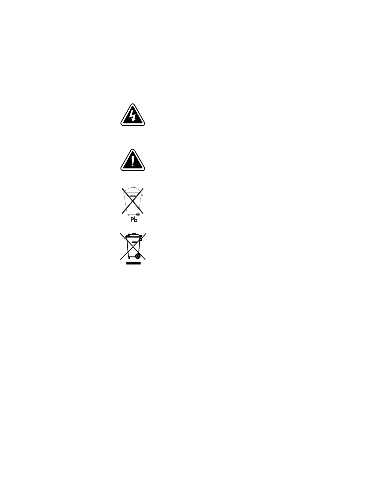
1.8 Symbols, Controls, and Indicators
The following are examples of symbols used on the UPS or accessories to alert you
to important information:
RISK OF ELECTRIC SHOCK - Observe the warning associated with the risk of electric
shock symbol.
CAUTION: REFER TO OPERATOR'S MANUAL - Refer to your operator's manual for
additional information, such as important operating and maintenance instructions.
This symbol indicates that you should not discard the UPS or the UPS batteries in the
trash. This product contains sealed, lead‐acid batteries and must be disposed of
properly. For more information, contact your local recycling/reuse or hazardous waste
center.
This symbol indicates that you should not discard waste electrical or electronic
equipment (WEEE) in the trash. For proper disposal, contact your local recycling/reuse
or hazardous waste center.
1-12
Eaton Power Xpert 9395P-600 (380V-600V) UPS Installation and Operation Manual S P-164000710 Rev 1 www.eaton.com/powerquality

1.9 For More Information
INTRODUCTION
Refer to the Eaton Power Xpert 9395 Integrated Battery Cabinet (Model 1085 and
1085HR) Installation Manual (P-164000580) for the following additional information:
S Integrated Battery Cabinet (IBC) installation instructions, including site preparation,
planning for installation, wiring, and safety information.
S Detailed illustrations of the cabinet, including dimension and connection point
drawings.
Refer to the Eaton Power Xpert 9395P Sync Control Installation and Operation Manual
(P164000502) for the following additional information:
S Installation instructions, including site preparation, planning for installation, and
wiring and safety information. Detailed illustrations of the cabinet with dimensional
and connection point drawings are provided.
S Operation, including controls, functions of the standard and optional features,
procedures for using with the UPS, and information about maintenance.
Refer to the Eaton Power Xpert 9395P UPS Field Installed UPM Mechanical
Installation Manual (P-164000503) for the following additional information:
1.10 Getting Help
S Mechanical installation instructions, including site preparation, planning for
mechanical installation, and safety information.
S Detailed illustrations of the cabinet, including dimension and pallet removal
drawings.
Visit www.eaton.com/powerquality or contact an Eaton service representative for
information on how to obtain copies of these manuals.
If help is needed with any of the following:
S Scheduling initial startup
S Regional locations and telephone numbers
S A question about any of the information in this manual
S A technical question this manual does not answer
Please call the Eaton Help Desk at:
United States:
Canada: 1-800-461-9166 ext 260
All other countries: Call your local service representative
Please use the following e-mail for manual comments, suggestions, or to report a
technical error in this manual.
1-800-843-9433 or 1-919-870-3028
E-ESSDocumentation@eaton.com
Eaton Power Xpert 9395P-600 (380V-600V) UPS Installation and Operation Manual S P-164000710 Rev 1 www.eaton.com/powerquality
1-13

INTRODUCTION
This page intentionally left blank.
1-14
Eaton Power Xpert 9395P-600 (380V-600V) UPS Installation and Operation Manual S P-164000710 Rev 1 www.eaton.com/powerquality

Chapter 2 Safety Warnings
Figure
IMPORTANT SAFETY INSTRUCTIONS
SAVE THESE INSTRUCTIONS
This manual contains important instructions that should be followed during installation and maintenance of
the UPS and batteries. Read all instructions before operating the equipment and save this manual for future
reference.
The UPS is designed for industrial or computer room applications, and contains safety shields behind the
door and front panels. However, the UPS is a sophisticated power system and should be handled with
appropriate care.
This UPS contains LETHAL VOLTAGES. All repairs and service should be performed by AUTHORIZED
SERVICE PERSONNEL ONLY. There are NO USER SERVICEABLE PARTS inside the UPS.
Cet onduleur peut générer des TENSIONS MORTELLES. L’installation et l’entretien ne doivent être
effectués que par le PERSONNEL AUTORISÉ. Ne contient AUCUNE PIÈCE REMPLAÇABLE.
D A N G E R
D A N G E R !
W A R N I N G
S The UPS is powered by its own energy source (batteries). The output terminals may carry live voltage
even when the UPS is disconnected from an AC source.
S To reduce the risk of fire or electric shock, install this UPS in a temperature and humidity controlled,
indoor environment, free of conductive contaminants. Ambient temperature must not exceed 40C
(104F) [35C 300 kW, 600 kW model]. Do not operate near water or excessive humidity (95% maximum).
The system is not intended for outdoor use.
S Ensure all power is disconnected before performing installation or service.
S Batteries can present a risk of electrical shock or burn from high short‐circuit current. The following
precautions should be observed: 1) Remove watches, rings, or other metal objects; 2) Use tools with
insulated handles; 3) Do not lay tools or metal parts on top of batteries; 4) Wear rubber gloves and boots.
S ELECTRIC ENERGY HAZARD. Do not attempt to alter any UPS or battery wiring or connectors. Attempting
to alter wiring can cause injury.
S As a result of the connected loads high leakage current is possible. Connection to earth ground is
required for safety and proper product operation. Do not check UPS operation by any action that includes
removal of the earth (ground) connection with loads attached.
S Do not open or mutilate batteries. Released electrolyte is harmful to the skin and eyes. It may be toxic.
A V E R T I S S E M E N T !
S L’onduleur est alimenté par sa propre source d’énergie (batteries). Les bornes de sortie peuvent être sous
tension, même lorsque l’onduleur est débranché d’une source de courant alternatif.
S Pour réduire les risques d’incendie et de décharge électrique, installer l’onduleur à l’intérieur, dans un
endroit exempt d’éléments conducteurs et où la température et l’humidité sont régulées. La température
ambiante ne doit pas dépasser 40 C (104 F) [35 C modèle 300 kW, 600 kW]. Ne pas faire fonctionner
près d’une source d’eau ou dans un endroit très humide (95 % maximum). Le système n’est pas conçu
pour une utilisation extérieure.
S Toutes les sources d’alimentation doivent être débranchées avant de procéder à l’installation et à
l’entretien.
Eaton Power Xpert 9395P-600 (380V-600V) UPS Installation and Operation Manual S P-164000710 Rev 1 www.eaton.com/powerquality
2-1

SAFETY WARNINGS
S Les batteries peuvent présenter un risque de décharge électrique ou de brûlure en raison du courant de
court-circuit élevé. Les précautions de base suivantes doivent être suivies : 1) retirer les montres, bagues
et autres objets métalliques; 2) utiliser des outils munis d’une poignée isolée; 3) ne pas déposer les outils
ou des pièces de métal sur les batteries; 4) porter des gants et des bottes en caoutchouc.
S DANGERS ÉLECTRIQUES. Ne pas tenter de modifier le câblage et les connecteurs de l’onduleur ou des
batteries. Toute tentative de modification peut provoquer des blessures.
S Les charges raccordées pourraient provoquer un courant de fuite élevé. La mise à la terre est donc
obligatoire pour garantir la sécurité et le bon fonctionnement du produit. Lors de la vérification du
fonctionnement de l’UPS, ne pas enlever la mise à la terre si des charges y sont raccordées.
S Ne pas ouvrir ni abîmer les batteries. L’électrolyte qu’elles contiennent est dangereux pour la peau et les
yeux. Il peut être toxique.
C A U T I O N
S Installation or servicing should be performed by qualified service personnel knowledgeable of UPS and
battery systems, and required precautions. Keep unauthorized personnel away from equipment. Consider
all warnings, cautions, and notes before installing or servicing equipment. DO NOT DISCONNECT the
batteries while the UPS is in Battery mode.
S Replace batteries with the same number and type of batteries as originally installed with the UPS.
S Disconnect the charging source prior to connecting or disconnecting terminals.
S Determine if the battery is inadvertently grounded. If it is, remove the source of the ground. Contacting
any part of a grounded battery can cause a risk of electric shock. An electric shock is less likely if you
disconnect the grounding connection before you work on the batteries.
S Proper disposal of batteries is required. Refer to local codes for disposal requirements.
S Do not dispose of batteries in a fire. Batteries may explode when exposed to flame.
S Keep the UPS door closed and front panels installed to ensure proper cooling airflow and to protect
personnel from dangerous voltages inside the unit.
S Do not install or operate the UPS system close to gas or electric heat sources.
S The operating environment should be maintained within the parameters stated in this manual.
S Keep surroundings uncluttered, clean, and free from excess moisture.
S Observe all DANGER, CAUTION, and WARNING notices affixed to the inside and outside of the
equipment.
2-2
MISE EN GARDE!
S L’installation et l’entretien doivent être effectués par du personnel qualifié en matière d’onduleurs et de
batteries, il doit connaître les précautions qui s’imposent. Le personnel non autorisé doit être tenu à
l’écart de l’équipement. Il est important de prendre connaissance des avertissements, des mises en
garde et des avis avant de procéder à l’installation ou à l’entretien de l’équipement. NE PAS
DÉBRANCHER les batteries lorsque l’onduleur est en mode Batterie..
S Ne jamais jeter les batteries au feu. L'exposition aux flammes risque de les faire exploser.
S Déconnecter la source d’alimentation avant de brancher ou débrancher les bornes.
S Vérifier que la batterie n’est pas, par inadvertance, reliée à la terre. Si c’est le cas, couper la source de
mise à la terre. Les contacts avec une batterie reliée à la terre peuvent provoquer des risques de
décharge électrique. Ces risques sont atténués si la mise à la terre est annulée avant le début des
travaux sur les batteries.
S L’élimination appropriée des batteries est requise. Se reporter aux codes locaux pour connaître les
exigences liées à l’élimination
S Ne pas jeter les batteries au feu. Les batteries peuvent exploser lorsqu’elles sont exposées à des
flammes.
S Garder les portes de l’onduleur fermées et les panneaux avant en place pour garantir une circulation
adéquate de l’air de refroidissement et pour protéger le personnel des tensions dangereuses dans
l’unité.
S Ne pas installer ni faire fonctionner l’onduleur près d’une source de chaleur au gaz ou à l’électricité.
Eaton Power Xpert 9395P-600 (380V-600V) UPS Installation and Operation Manual S P-164000710 Rev 1 www.eaton.com/powerquality

SAFETY WARNINGS
S Le milieu de fonctionnement doit toujours correspondre aux paramètres établis dans ce manuel.
S Maintenir les lieux rangés, propres et exempts d’une humidité excessive.
S Respecter les étiquettes DANGER, MISE EN GARDE et AVERTISSEMENT se trouvant à l’intérieur et à
l’extérieur de l’équipement.
C A U T I O N
To prevent damage to the wiring channel and wiring in the UPS cabinet base when lifting or moving the
cabinet:
S Lift and move the cabinet using only the front or rear forklift slots.
S Verify that the forklift forks are in a horizontal position before inserting them into the forklift slots.
DO NOT angle fork tips upward.
S Insert the forks all the way through the base. DO NOT insert forks partially into the base to move the
cabinet.
S Forks may be partially inserted into the front or rear forklift slots for minor positioning if the forks are
kept in a horizontal position with no upward angling.
S DO NOT use the forklift slots on the end of the cabinet to move the cabinet.
S End forklift slots may be used for minor positioning if the forks are kept in a horizontal position with no
upward angling.
If these instructions are not followed, damage to the wiring channel and wiring will occur.
MISE EN GARDE!
Pour éviter d’endommager le câblage et son canal à la base de l’armoire de l’onduleur lorsque l’armoire est
soulevée ou déplacée :
S Soulever ou déplacer l’armoire en n’utilisant que les passages de fourche à l’avant ou à l’arrière.
S Vérifier que les fourches du chariot élévateur sont en position horizontale avant de les insérer dans les
passages de fourche. NE PAS orienter les pointes de fourche vers le haut.
S Insérer complètement les fourches dans les passages de fourche de la base. NE PAS insérer
partiellement les fourches dans les passages pour déplacer l’armoire.
S Il est possible d’insérer partiellement les fourches dans les passages avant et arrière pour les petits
déplacements, et ce, si les fourches sont en position horizontale sans pointer vers le haut.
S NE PAS utiliser les passages de fourche à l’extrémité de l’armoire pour la déplacer.
S Les passages de fourche à l’extrémité de l’armoire peuvent servir lors des petits déplacements, et ce, si
les fourches sont en position horizontale sans pointer vers le haut.
Si ces instructions ne sont pas suivies, des dommages au câblage et à son canal surviendront.
Eaton Power Xpert 9395P-600 (380V-600V) UPS Installation and Operation Manual S P-164000710 Rev 1 www.eaton.com/powerquality
2-3

SAFETY WARNINGS
This page intentionally left blank.
2-4
Eaton Power Xpert 9395P-600 (380V-600V) UPS Installation and Operation Manual S P-164000710 Rev 1 www.eaton.com/powerquality
 Loading...