

Page 1
9376
MTL Trunk Surge Module
DRAFT - 28 July 2014
January 2017
INS9376 Rev 2
Instruction sheet
MTL fieldbus networks
1
Eaton Electric Limited,
Great Marlings, Butterfield, Luton
Beds, LU2 8DL, UK.
Tel: + 44 (0)1582 723633 Fax: + 44 (0)1582 422283
E-mail: mtlenquiry@eaton.com
www.mtl-inst.com
© 2017 Eaton
All Rights Reserved
Publication No. INS9376 Rev 2
January 2017
Introduction
T
he 9376-SP Trunk Surge module is designed to protect the 9370FB range of Fieldbus Barrier System from voltage and current
surges that could occur on the trunk wiring, and must be used only
with this equipment.
See the 9 376- SP technic al datash eet for full product details.
It is a 4- pin module that pl ugs into the upper end fa ce of the Trunk
Terminator A ssembl y (T TA) and is provided wi th pin conn ectors
that will p revent an ignition spa rk when the m odule is installed o r
removed.
The 9376-SP modul e may be in stal led or r emoved
with out is olati ng the t runk po wer.
READ SAFETY INFORMATION OVERLEAF
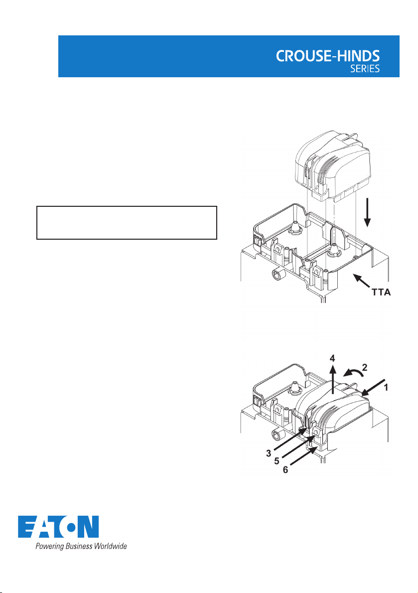
Inst alli ng a module
Remove the m odule fro m any packa ging provi ded.
Do not use, o r attempt to re pair, a module that has any of the pins
on its und erside bent or dama ged, bec ause this m ight affect its
safety and invalidate the certification.
Orient ate the modu le so that the smaller front clip is fa cing the
user, then:
• lower the module so th at the safet y retainin g clip (5) on the
TTA hous ing fits into the loop ( 6) on the mo dule,
• locate the terminal pins into thei r contac t sockets on t he
TTA hous ing, and push the mod ule home unt il front and re ar
retainin g clips are en gaged.
Remov ing a mod ule
Removal i s a two- step pro cess that f irst breaks the electrical
connec tion, foll owed by the ph ysical rem oval of the mo dule from
the TTA.
• Press the c lip at the rea r of the modu le (1) and lift th e rear of
the module (2) until the clip disengages.
• Press the f ront clip ( 3) and withdraw the mo dule from i ts
socket (4 ) until it is sto pped by the safety ret aining cli p (5).
• Press ag ainst the s afety clip enough to rel ease it and p ull the
module s traight ou t from the T TA body wi thout rot ating it.
Page 2

DRAFT - 28 July 2014
The given dat a is only intended as a prod uct
descriptio n and should not be regard ed as a legal
warranty of pr operties or guara ntee. In the interest
of further technical developments, we reserve the
right to make desig n changes.
2
MTL trunk surge module
January 2017
Eaton Electric Limited,
Great Marlings, Butterfield, Luton
Beds, LU2 8DL, UK.
Tel: + 44 (0)1582 723633 Fax: + 44 (0)1582 422283
E-mail: mtlenquiry@eaton.com
www.mtl-inst.com
© 2017 Eaton
All Rights Reserved
Publication No. INS9376 Rev 2 170117
January 2017
EUROPE (EMEA):
+44 (0)1582 723633
mtlenquiry@eaton.com
THE AMERICA
S:
+1 800 835 7075
mtl-us-info@eaton.com
ASIA-PACIFIC:
+65 6 645 9888
sales.mtlsing@eaton.com
ATEX and IECEx Safety Instructions for 9376-SP Trunk Surge
Module
The following infor mation is in accordance with t he
Essential Health and Safety Requirements (Annex II) of the
EU Direct ive 2014/34/EU [the ATEX D irective - safet y of apparatu s]
and is provided for tho se locat ions where such requirements are
applicable.
General
a) This module must on ly be installed, op erated an d
maintained by competent personnel. Such personnel shall
have unde rgone training, which included instruction on t he
various types of p rotectio n and insta llation practice s, the
relevant rules and regulations, and on the general principles
of area cla ssification. Appropri ate refresher training shall be
given on a re gular bas is. [See clause 4. 2 of EN 60 079 -17].
b) This module has be en design ed to provid e protection
against all the relevant additional hazards referred to in
Annex II of t he directive, such as those in clau se 1.2.7.
c) This module has been de signed to meet the requi rements of
EN 60 079 -0, E N 600 79-1, EN 6 0079-7, EN 60 079 -18.
Installation
d) The install ation must comply w ith the app ropriate Eu ropean,
national and local regulations, which may include referenc e
to the IEC co de of prac tice IEC 6 007 9-14. In addition ,
parti cular ind ustries o r end users m ay have spec ific
requirements relating to the safety of their installations and
these req uirements s hould als o be met. For t he majori ty of
install ations the Directi ve 1999 /92 /EC [the ATEX Directive safety of i nstalla tions] is als o applic able.
e) This module can be mounted in a Safe are a or a Zone 2 or
Zone 1 haz ardous are a. When mo unted in a Zon e 2 or Zone
1 locati on the mod ule must be p rovided w ith an encl osure,
which of fers an add itional d egree of protection ap propri ate
to the area classification.
f) Unless al ready protected by de sign, this m odule mus t be
protecte d by a suitab le enclos ure agains t:
i) mechanical and thermal stresses
in excess of th ose noted in t he certi fication docume ntation
and the product specification.
ii) aggressive substances, excessive dust, moisture and other
contaminants.
Read also the Schedule of Limitations (below) for any additional or
more specific information.
Schedule of Limitations
1) The 93 76- SP Trunk Surg e Protector must be housed in an
approp riately certifi ed Ex e enclosure.
2) The 93 76- SP Trunk Surg e Protecto r must plug in to
equipm ent that use s the socket part of the c onnector
covered by c ertificate TU V09 ATEX5 553 54U.
3) Due to the pre sence of tr ansient protection c omponents
between the fieldbus and earth connections, the
9376 -SP Trunk Surge Prote ctor will n ot withst and a 50 0V
a.c. dielectric s trength te st. This mu st be taken into account
during installation.
4) The ambient temper ature must not exeed +75°C.
5) The 93 76- SP Trunk Surg e Protecto r shall only be powered
from supp lies confo rming to IEC 61158.
6) The 93 76- SP Trunk Surg e Protecto r shall only be connec ted
into equip ment that c auses the se condary latching
connec tor to limit movement befor e the live -dem ateable
connec tor plug and socket meta l parts s eparate by over
1.9 mm.
Inspection and maintenance
Inspection and maintenance should be carried out in accordance
with European, nat ional and l ocal regulations w hich may refe r to
the IEC st andard IE C 600 79-17. In addit ion spec ific industries or
end users m ay have spe cific requirements w hich shou ld also be
met.
Repair
This module cannot be repaired by the user and must be
replaced with an equivalent certified product.
Marking
Each module is marked in compliance with the above
Directive and CE marked with the Notified Body
Identification Number.
This information applies to modules manufactured during or after
the year 2010.
 Loading...