

Eaton 9355 Series User Manual

Eaton®®9355 Parallel UPS
10/15 kVA
User's Guide
p/n: 164201601
Revision E0

Class A EMC Statements
!
FCC Part 15
NOTE This equipment has been tested and found to comply with the limits for a Class
ICES-003
This Class A Interference Causing Equipment meets all requirements of the Canadian Interference
Causing Equipment Regulations ICES-003.
Cet appareil numerique de la classe A respecte toutes les exigences du Reglement sur le materiel
brouilleur du Canada.
IEC 62040-2
Some configurations are classified under IEC 62040-2 as “C2 UPS for Unrestricted Sales
Distribution.”
A digital device, pursuant to part 15 of the FCC Rules. These limits are designed
to provide reasonable protection against harmful interference when the
equipment is operated in a commercial environment. This equipment
generates, uses, and can radiate radio frequency energy and, if not installed and
used in accordance with the instruction manual, may cause harmful
interference to radio communications. Operation of this equipment in a
residential area is likely to cause harmful interference in which case the user
will be required to correct the interference at his own expense.
IMPORTANT
To ensure you have the most up-to-date content and information for this product, please review the
latest manual revision on our website, www.eaton.com/9355.
Eaton reserves the right to change specifications without prior notice. Modbus is a registered trademark of Schneider Automation, Inc.
MOXA is a registered trademark and MGate is a trademark of MOXA, Inc. Spiralock is a registered trademark of Spiralock Corporation.
KIRK is a registered trademark of Kirk Key Interlock company, LLC, a subsidiary of Halma plc. National Electrical Code and NEC are
registered trademarks of National Fire Protection Association, Inc. ERIFLEX and FLEXIBAR are registered trademark of Erico International
Corporation. All other trademarks are property of their respective companies.
©Copyright 2005-2019 Eaton, Raleigh, NC, USA. All rights reserved. No part of this document may be reproduced in any way without the
express written approval of Eaton.

EATON
END-USER LICENSE AGREEMENT
IMPORTANT, READ CAREFULLY. THIS END USER LICENSE AGREEMENT (THE
“AGREEMENT”) IS A BINDING CONTRACT BETWEEN YOU, THE END-USER (THE
“LICENSEE”) AND EATON INTELLIGENT POWER LIMITED, IRELAND, OR ONE OF ITS
AFFILIATES (“EATON” OR “LICENSOR”). BY OPERATING THIS UNINTERRUPTIBLE
POWER SUPPLY (UPS) PRODUCT INCLUDING SOFTWARE EMBEDDED IN IT
(FIRMWARE), YOU, THE LICENSEE, ARE AGREEING TO BE BOUND BY THE TERMS,
CONDITIONS, AND LIMITATIONS OF THIS AGREEMENT. READ THE TERMS AND
CONDITIONS OF THIS AGREEMENT CAREFULL Y BEFORE, INST ALLING OR OPERATING
THE PRODUCT. IF YOU DO NOT AGREE TO THE TERMS OF THIS AGREEMENT,
PROMPTLY RETURN THE UNUSED PRODUCT TO EATON.
1.0 DEFINITIONS
1.1 Documentation. “Documentation” means the user guides and manuals for the installation
and use of the UPS, whether made available over the internet, provided in CD-ROM, DVD,
hard copy or other form.
1.2 Firmware. “Firmware” means software programs that are embedded in the product for
which Licensee is granted a license hereunder, the Documentation therefore and, to the extent
available, Updates thereto. The Firmware is licensed hereunder in object code (machinereadable) form only except that certain software programs may include limited portions in
source code (human-readable) form.
1.3 Update. “Update” means a subsequent release of the Firmware, if and when developed by
Eaton. An Update does not include any release, new version, option, or future product, which
Eaton licenses separately.
2.0 FIRMWARE LICENSE
2.1 Ownership. Eaton or its third party licensors retains all title, copyright and other proprietary
rights in, and ownership of the Firmware regardless of the media upon which the original or any
copy may be recorded or xed.
2.2 License Grant. Eaton grants to Licensee a limited, revocable, non-exclusive, non-assignable
license to use the Firmware in conjunction with the operation of the product to which the Firmware
pertains or other products as described by Eaton in the Documentation. Licensee does not
acquire any rights, express or implied, other than those expressly granted in this Agreement.
2.3 Restrictions and Requirements. Licensee will not, nor will it permit others to, modify,
adapt, translate, reverse engineer, decompile, or disassemble the Firmware or any component
thereof (including the Documentation), or create derivative works based on the Firmware
(including the Documentation), except to the extent such foregoing restriction is prohibited by
applicable law or applicable open source license to, and only to, any open source software
component that is incorporated into the Firmware (if any). Copyright laws and international
treaties protect the Firmware, including the Documentation. Unauthorized copying of the
Firmware, the Documentation or any part thereof, is expressly prohibited. For avoidance of
doubt, Eaton does not grant Licensee a license to any of Eaton’s brands, logos, designs, trade
dress, service marks, trademarks, domain names or trade names, in whole or in part.
Licensee agrees to install or allow installation of all corrections of substantial defects, security
patches, minor bug xes and updates, including any enhancements, for the Firmware in
accordance with the instructions and as directed by Eaton.
2.4 Transfer and Assignment Restrictions. Licensee will not sell, resell, assign, lease,
sublicense, encumber, or otherwise transfer its interest in this Agreement or in the Firmware,
or the Documentation in whole or in part, or allow any other person or entity, including any
parent or subsidiary of Licensee or other subsidiary of Licensee’s parent, to copy, distribute,
or otherwise transfer the Firmware without the prior written consent of Eaton. Licensee may
transfer the Firmware directly to a third party only in connection with the sale of the Eaton
product in which it is installed.
3.0 TERMINATION
3.1 Termination. This Agreement and the license granted hereunder automatically terminates
if Licensee breaches any provision of this Agreement. Eaton may terminate this license at any
time with or without cause.
3.2 Effect of Termination. Immediately upon termination of this Agreement or the license
granted hereunder, Licensee will cease using the product. The parties’ rights and obligations
under the following sections of this Agreement will survive termination of this Agreement: Article
1.0, Section 2.1, Section 2.3, Section 2.4, Article 3.0, Article 4.0 and Article 5.0.
4.0 INFRINGEMENT AND WARRANTIES
4.1 Infringement. If Licensee learns of a threat, demand, allegation, or indication that the
UPS with its rmware infringes or misappropriates any third party intellectual property rights
(including but not limited to any patent, copyright, trademark, trade dress, or trade secret)
(“Intellectual Property Claim”), Licensee will notify Eaton promptly of such claim. Eaton may, in
its sole discretion, elect to assume sole control of the defense and settlement of said Intellectual
Property Claim and Licensee will provide reasonable information and assistance to Eaton for
the defense of such claim.
4.2 Disclaimer of Warranties. THE FIRMWARE IS PROVIDED “AS IS” WITHOUT
WARRANTY OF ANY KIND, . EATON DOES NOT WARRANT THAT THE FIRMWARE
WILL BE ERROR-FREE OR SECURE FROM UNAUTHORIZED ACCESS. THE LICENSEE
EXPRESSLY ACKNOWLEDGES THAT TO THE EXTENT PERMITTED BY APPLICABLE
LAW, THE USE OF THE PRODUCT IS AT LICENSEE’S SOLE RISK.
5.0 GENERAL PROVISIONS
5.1 Update Policy. Eaton may from time to time, but has no obligation to, create Updates of
the Firmware or components thereof.
5.2 Limitation on Liability. NOTWITHSTANDING ANY PROVISION OF THIS AGREEMENT
TO THE CONTRARY, LICENSEE EXPRESSLY UNDERSTANDS AND AGREES THAT
EATON, ITS AFFILIATES, AND ITS LICENSORS, WILL NOT BE LIABLE FOR: (A) ANY
DIRECT, INDIRECT, INCIDENTAL, SPECIAL, CONSEQUENTIAL OR EXEMPLARY
DAMAGES WHICH MAY BE INCURRED BY LICENSEE OR ANY THIRD PARTY,
HOWEVER CAUSED AND UNDER ANY THEORY OF LIABILITY. THIS WILL INCLUDE,
BUT NOT BE LIMITED TO, ANY LOSS OF PROFIT (WHETHER INCURRED DIRECTLY OR
INDIRECTLY), ANY LOSS OF GOODWILL OR BUSINESS REPUTATION, ANY LOSS OF
DATA SUFFERED, COST OF PROCUREMENT OF SUBSTITUTE GOODS OR SERVICES,
OR OTHER INTANGIBLE LOSS; (B) ANY LOSS OR DAMAGE WHICH MAY BE INCURRED
BY LICENSEE OR ANY THIRD PARTY. THESE LIMITATIONS ON EATON’S LIABILITY WILL
APPLY WHETHER OR NOT EATON HAS BEEN ADVISED OF OR SHOULD HAVE BEEN
AWARE OF THE POSSIBILITY OF ANY SUCH LOSSES ARISING.
TO THE EXTENT PERMITTED BY LAW , THE TOT AL LIABILITY OF EA TON, ITS AFFILIA TES,
AND ITS LICENSORS, FOR ANY CLAIMS UNDER THESE TERMS, INCLUDING FOR ANY
IMPLIED WARRANTIES, IS LIMITED TO THE AMOUNT PAID FOR THE UPS.
THIS SECTION 5.2 STATES EATON’S ENTIRE LIABILITY AND LICENSEE’S SOLE AND
EXCLUSIVE REMEDY UNDER THIS AGREEMENT, AND IS SUBJECT TO ALL LIMITATIONS
STATED IN SECTION 4.2.
5.3 Notices. All notices required to be sent hereunder will be in writing and will be deemed to
have been given when mailed by rst class mail to the address shown below:
LICENSE NOTICES:
Eaton Intelligent Power Limited
Eaton House,
30 Pembroke Road,
Dublin 4,
D04 Y0C2,
Ireland
5.4 Severability. If any provision of this Agreement is held to be invalid or unenforceable, the
remaining provisions of this Agreement will remain in full force.
5.5 Waiver. The waiver by either party of any default or breach of this Agreement will not
constitute a waiver of any other or subsequent default or breach. Failure to enforce or delay in
enforcing any provision of this Agreement will not constitute a waiver of any rights under any
provisions of this Agreement.
5.6 Entire Agreement. This Agreement constitutes the complete agreement between the
parties and supersedes all prior or contemporaneous agreements or representations, written
or oral, concerning the subject matter of this Agreement. This Agreement may not be modied
or amended except in a writing specically referencing this Agreement and signed by a duly
authorized representative of each party. No other act, document, usage or custom will be
deemed to amend or modify this Agreement. The Firmware, or portions thereof, may also
be subject to additional paper or electronic license agreements. In such cases, the terms of
this Agreement will be supplemental to those in the additional agreements, to the extent not
inconsistent with the additional agreements. If a copy of this Agreement in a language other
than English is included with the Firmware or Documentation, it is included for convenience and
the English language version of this Agreement will control.
5.7 Heirs, Successors, and Assigns. Each and all of the covenants, terms, provisions
and agreements herein contained will be binding upon and inure to the benet of the parties
hereto and, to the extent expressly permitted by this Agreement, their respective heirs, legal
representatives, successors and assigns.
5.8 Export Restrictions. Licensee agrees to comply fully with all relevant export laws and
regulations of the United States and all other countries in the world (the “Export Laws”) to
assure that neither the Firmware nor any direct product thereof are (I) exported, directly or
indirectly, in violation of Export Laws; or (ii) are intended to be used for any purposes prohibited
by the Export Laws. Without limiting the foregoing, Licensee will not export or re-export the
Firmware: (i) to any country to which the U.S. has embargoed or restricted the export of
goods or services (see http://www.treasury.gov/resource-center/sanctions/Programs/Pages/
Programs.aspx), or to any national of any such country, wherever located, who intends to
transmit or transport the Firmware back to such country; (ii) to any end user who Licensee
knows or has reason to know will utilize the Firmware in the design, development or production
of nuclear, chemical or biological weapons; or (iii) to any end-user who has been prohibited
from participating in U.S. export transactions by any federal agency of the U.S. government.
5.9 U.S. Government Restricted Rights. The Firmware is a “commercial item” as that term
is dened at 48 C.F.R. § 2.101, consisting of “commercial computer software” and “commercial
computer software documentation”, as such terms are used in 48 C.F.R. § 12.212, and is
provided to the U.S. Government only as a commercial end item. Consistent with 48 C.F.R.
§ 12.212 and 48 C.F.R. §§ 227.7202-1 through 227.7202-4, all U.S. Government End Users
acquire the Firmware with only those rights set forth herein. Contractor/manufacturer is Eaton
Corporation, 1000 Eaton Boulevard, Cleveland, Ohio 44122.
5.10 Third Party Intellectual Property Rights. The Firmware may contain components
(including open source software components) that are owned by third parties (“Third Party
Licensors”) and are provided with, incorporated into, or embedded in, the Firmware pursuant to
license arrangements between Eaton and such third parties. Third Party Licensor components
in the Firmware are not licensed or warranted under the terms of this document, but are instead
subject to the Third Party Licensors’ license agreements. Licensee will not modify, delete, or
obfuscate any copyright or other proprietary rights notices of Third Party Licensors contained
in the Firmware.
5.11 Indemnity. Licensee shall defend, indemnify and hold Eaton and its ofcers, directors,
employees, and agents harmless from and against all losses, damages, liabilities, claims,
actions, and associated costs and expenses (including reasonable attorneys’ fees and expenses)
by reason of injury or death to any person or damage to any tangible or intangible property arising
or resulting from the negligence or willful misconduct of the Licensee, its employees, contractors,
or agents, in connection with Licensee’s use of Firmware and Documentation.
Licensee shall be responsible for any breach of this Agreement by its ofcers, directors,
employees, contractors, or agents. Licensee shall defend, indemnify, and hold Eaton and
its ofcers, directors, employees, and agents harmless from and against any and all losses,
damages, liabilities, claims, actions, and associated costs and expenses (including reasonable
attorneys’ fees and expenses) arising out of or in connection with any breach of this Agreement.
5.12 Open Source Software. The Firmware may contain certain components owned by
Eaton that are provided with, incorporated into, linked to, or embedded in the Firmware that are
subject to third party open source licenses (“Eaton Open Source Components”). Eaton Open
Source Components are subject to the open source licenses corresponding to the particular
software component. To the extent there are any conicts between the terms of this Agreement
and any open source license corresponding to Eaton Open Source Components or additional
obligations by such open sources license that are not set forth in this Agreement, the terms of
the open source license will control.
5.13 Condentiality. Licensee acknowledges that condential aspects of the Firmware
(including any proprietary source code) are a trade secret of Eaton, the disclosure of which
would cause substantial harm to Eaton that could not be remedied by the payment of damages
alone and such condential aspects of the Firmware shall not be disclosed to third parties
without the prior written consent of Eaton. Accordingly, Eaton will be entitled to preliminary and
permanent injunctive and other equitable relief for any breach of this Section 5.13.
5.14 Note on JAV A Support. The Firmware may contain support for programs written in JAVA.
JAVA technology is not fault tolerant and is not designed, manufactured, or intended for use or
resale as online control equipment in hazardous environments requiring fail-safe performance,
such as in the operation of nuclear facilities, aircraft navigation or communications systems, air
trafc control, direct life support machines, or weapons systems, in which the failure of JAVA
technology could lead directly to death, personal injury, or severe physical or environmental
damage. EATON DISCLAIMS ALL DAMAGES INCLUDING DIRECT, INDIRECT AND
CONSEQUENTIAL DAMAGES RELATING TO THE FAILURE OF ANY SOFTWARE
INCLUDING JAVA PROGRAMS AND/OR JAVA TECHNOLOGY.
5.15 Governing Law. This Agreement will be interpreted and enforced in accordance with the
laws of Ireland, without regard to choice of law principles. Any claim or suit with respect to this
Agreement shall be brought in the Courts of Ireland, unless mandatory law imposes otherwise.
Eaton EULA
P-110000654-001 Revised: December 21st, 2018


TTaabbllee ooff CCoonntteennttss
11 IInnttrroodduuccttiioonn....................................................................................................................................................................................................................................................................................................11
1.1 Using This Manual ......................................................................................................................................2
1.2 Conventions Used in This Manual .................................................................................................................. 2
1.3 Symbols, Controls, and Indicators .................................................................................................................. 3
1.4 For More Information ..................................................................................................................................3
1.5 Getting Help..............................................................................................................................................4
1.6 Equipment Registration ............................................................................................................................... 4
22 SSaaffeettyy WWaarrnniinnggss........................................................................................................................................................................................................................................................................................55
2.1 Consignes de Sécurité ................................................................................................................................. 6
2.1.1 CONSIGNES DE SÉCURITÉ IMPORTANTES CONSERVER CES INSTRUCTIONS CE MANUEL CONTIENT DES
CONSIGNES DE SÉCURITÉ IMPORTANTES............................................................................................................6
2.2 Advertencias de Seguridad ...........................................................................................................................7
2.2.1 INSTRUCCIONES DE SEGURIDAD IMPORTANTES GUARDE ESTAS INSTRUCCIONES ESTE MANUAL
CONTIENE INSTRUCCIONES DE SEGURIDAD IMPORTANTES................................................................................... 7
33 UUPPSS IInnssttaallllaattiioonn PPllaann aanndd UUnnppaacckkiinngg ............................................................................................................................................................................................................................99
3.1 Creating an Installation Plan .......................................................................................................................... 9
3.2 Preparing the Site .......................................................................................................................................9
3.2.1 Environmental and Installation Considerations ............................................................................................9
3.3 Parallel UPS System Power Wiring Preparation ............................................................................................... 11
3.4 Inspecting the Equipment........................................................................................................................... 12
44 UUPPSS SSyysstteemm IInnssttaallllaattiioonn.............................................................................................................................................................................................................................................................. 1133
4.1 Preliminary Installation Information............................................................................................................... 13
4.2 Unloading the UPS Cabinet from the Pallet..................................................................................................... 13
4.2.1 Three-High Cabinets or Two-High EBMs.................................................................................................. 13
4.2.2 Two-High UPS Cabinets ....................................................................................................................... 16
4.3 External AC Power Wiring Installation ........................................................................................................... 19
4.3.1 Version 1 Tie Cabinet Parallel Installation ................................................................................................. 19
4.3.2 Version 2 Tie Cabinet Parallel Installation ................................................................................................. 25
4.3.3 Installing Options................................................................................................................................ 34
4.3.3.1 Powerware Hot Sync CAN Bridge Card............................................................................................ 35
4.3.4 Stabilizing the Cabinet.......................................................................................................................... 39
4.4 Extended Battery Module Installation............................................................................................................ 41
55 UUPPSS WWiirriinngg DDiiaaggrraamm SScchheemmaattiiccss.................................................................................................................................................................................................................................... 4455
66 OOppeerraattiioonn........................................................................................................................................................................................................................................................................................................ 4499
6.1 Control Panel Functions ............................................................................................................................. 49
6.1.1 Changing the Language........................................................................................................................ 49
6.1.2 Display Functions ............................................................................................................................... 49
6.1.3 User Settings..................................................................................................................................... 50
Eaton 9355 Parallel UPS (10/15 kVA) User's Guide 164201601—Rev E0 v

Table of Contents
6.2 Initial Startup ........................................................................................................................................... 52
6.2.1 Parallel UPS Startup ............................................................................................................................ 53
6.3 Configuring the UPS for EBMs .................................................................................................................... 54
6.4 Parallel System Shutdown .......................................................................................................................... 55
6.5 Individual UPS Shutdown ........................................................................................................................... 55
6.6 Restarting the Parallel System..................................................................................................................... 56
6.7 Parallel Bypass Operation ........................................................................................................................... 56
77 TTrroouubblleesshhoooottiinngg.................................................................................................................................................................................................................................................................................... 5599
7.1 Typical Alarms and Conditions..................................................................................................................... 59
7.2 Silencing the Alarm ................................................................................................................................... 60
88 WWaarrrraannttyy ...................................................................................................................................................................................................................................................................................................... 6611
vi Eaton 9355 Parallel UPS (10/15 kVA) User's Guide 164201601—Rev E0

LLiisstt ooff FFiigguurreess
Figure 1. The Eaton 9355 UPS and EBM (3-High Cabinets Shown) ........................................................................ 1
Figure 2. Removing the Stabilizing Bracket Bolts ............................................................................................. 14
Figure 3. Removing the Brackets and Shipping Pad.......................................................................................... 15
Figure 4. Unloading the Cabinet................................................................................................................... 16
Figure 5. Removing the Pallet...................................................................................................................... 16
Figure 6. Removing the Vertical Bracket ........................................................................................................ 17
Figure 7. Reinstalling the M4 Screws and Remove Pallet Brackets...................................................................... 17
Figure 8. Removing the Front Shipping Bracket and Shipping Pad ....................................................................... 18
Figure 9. Unloading the Cabinet................................................................................................................... 19
Figure 10. Removing the Pallet...................................................................................................................... 19
Figure 11. Version 1 Parallel Tie Cabinet Front Cover.......................................................................................... 20
Figure 12. Version 1 Internal Cover................................................................................................................. 21
Figure 13. Version 1 Parallel Bypass Breaker .................................................................................................... 21
Figure 14. UPS Rear View (3-High Shown)....................................................................................................... 22
Figure 15. UPS Terminal Block (3-High Shown)................................................................................................. 23
Figure 16. Version 1 UPS Output to Parallel Tie Cabinet Wiring ............................................................................ 23
Figure 17. Version 1 Load Connections ........................................................................................................... 24
Figure 18. Version 1 Bypass AC Input Wiring.................................................................................................... 25
Figure 19. Version 2 Parallel Tie Cabinet Front Door and Cover............................................................................. 26
Figure 20. Version 2 Parallel Tie Cabinet Front Cover Open.................................................................................. 27
Figure 21. Version 2 Parallel Tie Cabinet Internal Cover....................................................................................... 28
Figure 22. Version 2 Parallel Tie Cabinet Bypass Breaker .................................................................................... 29
Figure 23. UPS Rear View (3-High Shown)....................................................................................................... 30
Figure 24. UPS Terminal Block (3-High Shown)................................................................................................. 31
Figure 25. Version 2 Tie Cabinet UPS Output to Parallel Tie Wiring........................................................................ 32
Figure 26. Version 2 Tie Cabinet Load Connections............................................................................................ 33
Figure 27. Version 2 Tie Cabinet Bypass AC Input Wiring .................................................................................... 34
Figure 28. Communication Options and Control Terminals .................................................................................. 35
Figure 29. Powerware Hot Sync CAN Bridge Card............................................................................................. 35
Figure 30. Removing the Front Covers ............................................................................................................ 36
Figure 31. CAN Bridge Card Wiring ................................................................................................................ 37
Figure 32. Removing Knockout Tabs .............................................................................................................. 38
Figure 33. Reinstalling the Front Covers .......................................................................................................... 38
Figure 34. Lowering the Leveling Feet ............................................................................................................ 39
Figure 35. Stabilizing Bracket with One Cabinet ................................................................................................ 40
Figure 36. Stabilizing Bracket with Two Cabinets .............................................................................................. 40
Figure 37. Stabilizing Bracket with Three Cabinets............................................................................................. 41
Figure 38. Typical EBM Installation (2-High Cabinets Shown) ............................................................................... 42
Figure 39. Front Ground Strap Installation (2-High Cabinets Shown) ...................................................................... 43
Eaton 9355 Parallel UPS (10/15 kVA) User's Guide 164201601—Rev E0 vii

List of Figures
Figure 40. Version 1 Tie Cabinet Parallel Wiring Diagram..................................................................................... 45
Figure 41. Version 1 Tie Cabinet Parallel UPS Schematic..................................................................................... 46
Figure 42. Version 2 Tie Cabinet Parallel Wiring Diagram – without Maintenance Isolation Switch (MIS)........................ 47
Figure 43. Version 2 Bypass Cabinet Bypass Wiring Diagram – with MIS................................................................ 47
Figure 44. Version 2 Tie Cabinet Parallel UPS Schematic..................................................................................... 48
Figure 45. Eaton 9355 UPS Control Panel ........................................................................................................ 49
viii Eaton 9355 Parallel UPS (10/15 kVA) User's Guide 164201601—Rev E0

LLiisstt ooff TTaabblleess
Table 1. Air Conditioning or Ventilation Requirements During Full Load Operation................................................... 10
Table 2. UPS Cabinet Weights ..................................................................................................................... 10
Table 3. UPS Cabinet Clearances ................................................................................................................. 11
Table 4. Eaton 9355 10–15 kVA Parallel UPS: Recommended Terminal Block Wiring .............................................. 12
Table 5. Menu Map for Display Functions ...................................................................................................... 50
Table 6. User Settings................................................................................................................................ 51
Eaton 9355 Parallel UPS (10/15 kVA) User's Guide 164201601—Rev E0 ix

List of Tables
x Eaton 9355 Parallel UPS (10/15 kVA) User's Guide 164201601—Rev E0
CChhaapptteerr 11 IInnttrroodduuccttiioonn
!
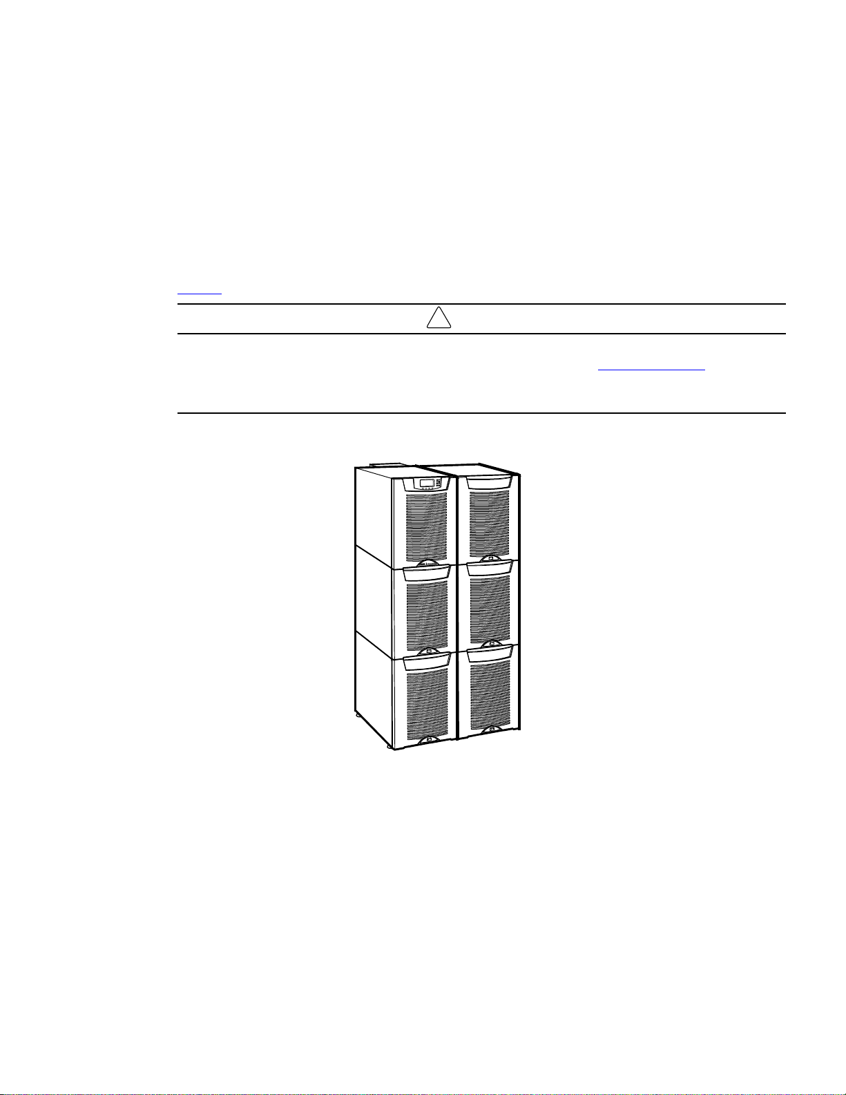
A parallel system with up to four uninterruptible power supplies (UPSs) can be installed to provide a parallel
capacity and/or redundant system. This load sharing system provides more capacity than a single UPS and can
provide backup, depending on the load and configuration. In addition, when one UPS is taken out of service for
maintenance or is not operating properly, a redundant UPS continues to supply uninterrupted power to the
critical load. A parallel Powerware Hot Sync
operational mode control. The parallel system consists of two to four UPSs, each with a parallel CAN Bridge
Card and a parallel cabinet.
Figure 1 shows the Eaton 9355 UPS and an optional Extended Battery Module (EBM).
Startup and operational checks must be performed by an authorized Eaton Customer Service Engineer, or the
warranty terms specified on the product's resources page become void. See Chapter 8 Warranty for details.
This service is offered as part of the sales contract for the UPS. Contact an Eaton service representative in
advance (a minimum two-week notice is required) to reserve a preferred startup date.
Figure 1. The Eaton 9355 UPS and EBM (3-High Cabinets Shown)
®
CAN Bridge Card provides connectivity for system metering and
IMPORTANT
Providing outstanding performance and reliability, the Eaton 9355 UPS's unique benefits including the
following:
• Online UPS design with pure sine wave output. The UPS filters and regulates incoming AC power and
provides consistent power to your equipment without draining the battery.
• More wattage in less space with a 0.9 power factor–protecting more equipment and leaving more room
for expansion.
• Support for Powerware Hot Sync paralleling of multiple modules for redundancy or extra capacity.
• Input current total harmonic distortion (THD) of less than five percent, using active input power factor
correction.
Eaton 9355 Parallel UPS (10/15 kVA) User's Guide 164201601—Rev E0 1

Introduction
• ABM®technology that uses advanced battery management to increase battery service life, optimize
recharge time, and provide a warning before the end of useful battery life.
• Up to three hours of extended runtime with added EBMs.
• Advanced power management with the Software Suite CD for graceful shutdowns and power monitoring.
• Emergency shutdown control through the remote emergency power-off (REPO) port.
• Start-on-battery capability for powering up the UPS even if utility power is not available.
• Standard communication options with a DB-9 serial port, relay output contacts, and programmable signal
inputs.
• Optional X-Slot
control.
For further details on available options, see Eaton 9355 UPS 10/15 kVA User’s Guide.
11..11 UUssiinngg TThhiiss MMaannuuaall
This manual describes how to install and operate the Eaton 9355 UPS. Read and understand the procedures
described in this manual to ensure trouble-free installation and operation. In particular, be thoroughly familiar
with the REPO procedure or the LOAD OFF procedure, see Chapter 6 UPS Operating Instructions.
®
cards with enhanced communication capabilities for increased power protection and
The information in this manual is divided into sections and chapters. The system, options, and accessories
being installed dictate which parts of this manual should be read. At a minimum, Chapter 1 Introduction
through Chapter 4 UPS System Installation and Chapter 6 UPS Operating Instructions should be
examined.
Read through each procedure before beginning the work. Perform only those procedures that apply to the UPS
system being installed or operated.
11..22 CCoonnvveennttiioonnss UUsseedd iinn TThhiiss MMaannuuaall
This manual uses these type conventions:
• Bold type highlights important concepts in discussions, key terms in procedures, and menu options, or
represents a command or option that you type or enter at a prompt.
• Italic type highlights notes and new terms where they are defined.
• Screen type represents information that appears on the screen or LCD.
Icon
Note Information notes call attention to important features or instructions.
[Keys] Brackets are used when referring to a specific key, such as [Enter] or [Ctrl].
In this manual, the term UPS refers only to the UPS cabinet and its internal elements. The term UPS system
refers to the entire power protection system – the UPS cabinet, an external battery system, and options or
accessories installed.
Description
The term line-up-and-match refers to accessory cabinets that are physically located adjacent to the UPS. The
term standalone refers to accessory cabinets that are located separate from the UPS.
Left and right side notations are referenced standing in front of the cabinet.
2 Eaton 9355 Parallel UPS (10/15 kVA) User's Guide 164201601—Rev E0
11..33 SSyymmbboollss,, CCoonnttrroollss,, aanndd IInnddiiccaattoorrss
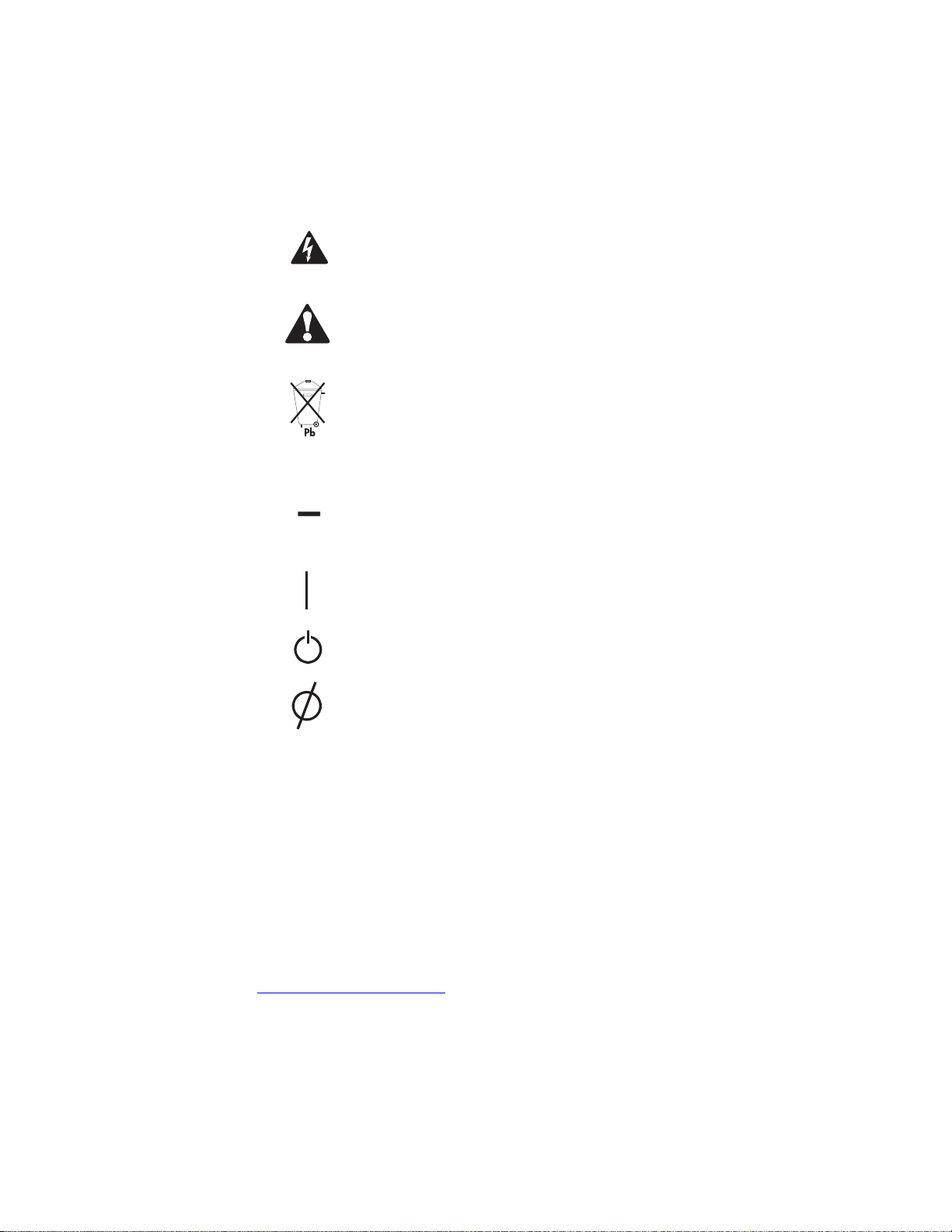
The following are examples of symbols used on the product to alert you to important information:
Introduction
RISK OF ELECTRIC SHOCK - Observe the warning associated with the risk of electric
shock symbol.
CAUTION: REFER TO OPERATOR'S MANUAL - Refer to your operator's manual for
additional information, such as important operating and maintenance instructions.
This symbol indicates that you should not discard the product in the trash. This product
must be disposed of properly. For more information, contact your local recycling/reuse or
hazardous waste center.
This symbol indicates that you should not discard waste electrical or electronic
equipment (WEEE) in the trash. For proper disposal, contact your local recycling/reuse or
hazardous waste center.
11..44 FFoorr MMoorree IInnffoorrmmaattiioonn
Refer to the Eaton 9355 UPS 10/15 kVA User’s Guide for the following additional information:
• Installation instructions, including site preparation, planning for installation, wiring and safety information,
and detailed illustrations of cabinets with dimensional and connection point drawings
• Operation, including breakers, standard features and optional accessories, procedures for using the bypass
functions, and information about maintenance
Refer to the Eaton Remote Monitoring Device (RMD) Installation and Operation Manual for additional
installation and operating instructions.
• Visit www.eaton.com/powerquality or contact an Eaton service representative for information on how to
obtain copies of these manuals.
ON - Indicates that the switch is in the ON position.
OFF - Indicates that the switch is in the OFF position.
PHASE - The word “phase.”
Eaton 9355 Parallel UPS (10/15 kVA) User's Guide 164201601—Rev E0 3

Introduction
11..55 GGeettttiinngg HHeellpp
If help is needed with any of the following:
• Scheduling initial startup
• Regional locations and telephone numbers
• A question about any of the information in this manual
• A question this manual does not answer
Please call the Customer Reliability Center at:
United States:
Canada:
All other countries: Call your local service representative
Please have the following information ready when you call for service:
• Model number
• Serial number
• Firmware version number
• Date of failure or problem
• Symptoms of failure or problem
• Customer return address and contact information
Please use the following e-mail address for manual comments, suggestions, or to report an error in this
manual:
E-ESSDocumentation@eaton.com
11..66 EEqquuiippmmeenntt RReeggiissttrraattiioonn
Please visit www.eaton.com/pq/register to register your new Eaton UPS / Eaton UPS Accessory.
Model Number:
1-800-843-9433
1-800-461-9166 ext 260
Serial Number:
4 Eaton 9355 Parallel UPS (10/15 kVA) User's Guide 164201601—Rev E0

CChhaapptteerr 22 SSaaffeettyy WWaarrnniinnggss
IMPORTANT SAFETY INSTRUCTIONS SAVE THESE INSTRUCTIONS
This manual contains important instructions that you should follow during installation and maintenance of the
UPS and batteries. Please read all instructions before operating the equipment and save this manual for future
reference.
This UPS contains LETHAL VOLTAGES. All repairs and service should be performed by AUTHORIZED
SERVICE PERSONNEL ONLY. There are NO USER SERVICEABLE PARTS inside the UPS.
• This UPS contains its own energy source (batteries). The UPS output may carry live voltage even when the
UPS is not connected to an AC supply.
• To reduce the risk of fire or electric shock, install this UPS in a temperature and humidity controlled, indoor
environment, free of conductive contaminants. Ambient temperature must not exceed 40°C (104°F). Do
not operate near water or excessive humidity (95% maximum).
• To reduce the risk of fire, connect only to a circuit provided with 100 amperes maximum branch circuit
overcurrent protection in accordance with the National Electrical Code
• Output overcurrent protection and disconnect switch must be provided by others.
DANGER
WARNING
®
(NEC®), ANSI/NFPA 70.
CAUTION
• Batteries can present a risk of electrical shock or burn from high short circuit current. Observe proper
precautions. Servicing should be performed by qualified service personnel knowledgeable of batteries and
required precautions. Keep unauthorized personnel away from batteries.
• Proper disposal of batteries is required. Refer to your local codes for disposal requirements.
• Never dispose of batteries in a fire. Batteries may explode when exposed to flame.
Eaton 9355 Parallel UPS (10/15 kVA) User's Guide 164201601—Rev E0 5

Safety Warnings
22..11 CCoonnssiiggnneess ddee SSééccuurriittéé
22..11..11 CCOONNSSIIGGNNEESS DDEE SSÉÉCCUURRIITTÉÉ IIMMPPOORRTTAANNTTEESS CCOONNSSEERRVVEERR CCEESS IINNSSTTRRUUCCTTIIOONNSS CCEE MMAANNUUEELL
CCOONNTTIIEENNTT DDEESS CCOONNSSIIGGNNEESS DDEE SSÉÉCCUURRIITTÉÉ IIMMPPOORRTTAANNTTEESS
Cet onduleur contient des TENSIONS MORTELLES. Toute opération d'entretien et de réparation doit être
EXCLUSIVEMENT CONFIÉE A UN PERSONNEL QUALIFIÉ AGRÉÉ. AUCUNE PIÈCE RÉPARABLE PAR
L'UTILISATEUR ne se trouve dans l'onduleur.
• Cet onduleur renferme sa propre source d'énergie (batteries). Les prises de sortie peuvent être sous
tension même lorsque l'onduleur n'est pas branché sur le secteur.
• Pour réduire les risques d'incendie et de décharge électrique, installer l'onduleur uniquement à l'intérieur,
dans un lieu dépourvu de matériaux conducteurs, où la température et l'humidité ambiantes sont
contrôlées. La température ambiante ne doit pas dépasser 40 °C. Ne pas utiliser à proximité d'eau ou dans
une atmosphère excessivement humide (95 % maximum).
• La protection contre une surintensité pour le(s) circuit(s) de sortie de courant alternatif doit être fournie par
un autre fournisseur.
• Les interrupteurs de déconnexion convenables pour le(s) circuit(s) de sortie de courant alternatif doivent
être fournie par un autre fournisseur.
DANGER!
AVERTISSEMENT!
ATTENTION!
• Les batteries peuvent présenter un risque de décharge électrique ou de brûlure par des courts-circuits de
haute intensité. Prendre les précautions nécessaires.
• Une mise au rebut réglementaire des batteries est obligatoire. Consulter les règlements en vigueur dans
votre localité.
• Ne jamais jeter les batteries au feu. L'exposition aux flammes risque de les faire exploser.
6 Eaton 9355 Parallel UPS (10/15 kVA) User's Guide 164201601—Rev E0

22..22 AAddvveerrtteenncciiaass ddee SSeegguurriiddaadd
22..22..11 IINNSSTTRRUUCCCCIIOONNEESS DDEE SSEEGGUURRIIDDAADD IIMMPPOORRTTAANNTTEESS GGUUAARRDDEE EESSTTAASS IINNSSTTRRUUCCCCIIOONNEESS EESSTTEE
MMAANNUUAALL CCOONNTTIIEENNEE IINNSSTTRRUUCCCCIIOONNEESS DDEE SSEEGGUURRIIDDAADD IIMMPPOORRTTAANNTTEESS
PELIGRO
Este SIE contiene VOLTAJES MORTALES. Todas las reparaciones y el servicio técnico deben ser efectuados
SOLAMENTE POR PERSONAL DE SERVICIO TÉCNICO AUTORIZADO. No hay NINGUNA PARTE QUE EL
USUARIO PUEDA REPARAR dentro del SIE.
ADVERTENCIA
• Este SIE contiene su propia fuente de energía (las baterías). Los receptáculos de salida pueden transmitir
corriente eléctrica aun cuando el SIE no esté conectado a un suministro de corriente alterna (c.a.).
• Para reducir el riesgo de incendio o de choque eléctrico, instale este SIE en un lugar cubierto, con
temperatura y humedad controladas, libre de contaminantes conductores. La temperatura ambiente no
debe exceder los 40°C. No trabaje cerca del agua o con humedad excesiva (95% máximo).
• La protección contra exceso de corriente para el/los circuito(s) de CA de salida será suministrada por
terceros.
• Los interruptores de desconexión debidamente clasificados para el/los circuito(s) de CA de salida serán
suministrados por terceros.
Safety Warnings
PRECAUCIÓN
• Las baterías pueden presentar un riesgo de descargas eléctricas o de quemaduras debido a la alta
corriente de cortocircuito. Preste atención a las instrucciones correspondientes.
• Es necesario desechar las baterías de un modo adecuado. Consulte las normas locales para conocer los
requisitos pertinentes.
• Nunca deseche las baterías en el fuego. Las baterías pueden explotar si se las expone a la llama.
Eaton 9355 Parallel UPS (10/15 kVA) User's Guide 164201601—Rev E0 7

Safety Warnings
8 Eaton 9355 Parallel UPS (10/15 kVA) User's Guide 164201601—Rev E0

CChhaapptteerr 33 UUPPSS IInnssttaallllaattiioonn PPllaann aanndd UUnnppaacckkiinngg
Use the following basic sequence of steps to install the UPS:
1. Create an installation plan for the UPS system.
2. Prepare your site for the UPS system.
3. Inspect and unpack the UPS cabinet.
4. Unload and install the UPS cabinet, and wire the system.
5. Complete the Installation Checklist.
6. Have authorized service personnel perform preliminary operational checks and start up the system.
The instructions are intended for the chief operator/system supervisor, electrical consultants, and installation
electricians. Local regulations and electrical code must be followed during the UPS installation.
33..11 CCrreeaattiinngg aann IInnssttaallllaattiioonn PPllaann
Before installing the UPS system, read and understand how this manual applies to the system being installed.
Use this chapter’s procedures and illustrations and those in Chapter 4 UPS System Installation to create a
logical plan for installing the system.
33..22 PPrreeppaarriinngg tthhee SSiittee
For the UPS system to operate at peak efficiency, the installation site should meet the environmental
parameters outlined in this manual. The operating environment must meet the weight, clearance, and
environmental requirements specified.
33..22..11 EEnnvviirroonnmmeennttaall aanndd IInnssttaallllaattiioonn CCoonnssiiddeerraattiioonnss
The UPS system installation must meet the following guidelines:
• The system must be installed on a level floor suitable for computer or electronic equipment.
• The system must be operated at an altitude no higher than 1500m (5000 ft) without derating. For additional
assistance with high altitude operation, contact an Eaton service representative (see paragraph
1.5 Getting Help).
• The system must be installed in a temperature and humidity controlled indoor area free of conductive
contaminants.
CAUTION
Do not expose the UPS to overly aggressive environments, like salt mist or corrosive gases. High relative
humidity accelerates the effects of contaminants. The UPS should be installed in a G1 environment (based on
ANSI/ISA S-71.04 classifications). If the UPS is used in a more aggressive environment, it can cause reduced
product life and possibly early failure. If the installation location does not meet the recommended environment,
contact Eaton service representative for further information (see paragraph 1.5 Getting Help).
• The environmental requirements specified below are for the air at the intake ports of the 93PM UPS, and
are the maximum, not to exceed, ratings.
– There shall be at least a 1.8°F (1.0°C) difference between the dry bulb temperature and the wet bulb
temperature, at all times, to maintain a non-condensing environment.
– The maximum rate of temperature change shall be limited to 3°F over 5 minutes (36°F/hour), based on
the ASHRAE Standard 90.1-2013.
Eaton 9355 Parallel UPS (10/15 kVA) User's Guide 164201601—Rev E0 9
UPS Installation Plan and Unpacking
• The newer, more energy efficient data center cooling methods (such as air side economization) can create
much wider ranges of temperature and Relative Humidity (RH) in the UPS room and/or data center. There
are two aspects of this increased operating environment that can, if ignored, create issues.
– One is the creation of microclimates, which are persistent variations of temperature and/or RH within
a single room. For example one side of the room is always cooler than the other side, no matter the
actual temperature.
– The other aspect is the rate of change of temperature and/or RH, which can occur during transitions
within the cooling system. Examples: changing the mixture ratio of inside versus outside air, or
external changes in the outside air when going from night to day, and back to night.
– When ignored, either one of these aspects can create an undesirable microclimate at the UPS
location. If the environment created by this microclimate exceeds the UPS operating specification, the
UPS reliability, over time, will be reduced. These same environmental extremes will also create
reliability concerns for any servers that are exposed to them.
The basic environmental requirements for operation of the UPS are:
• Ambient Temperature Range: 5–40°C (41–104°F)
• Recommended Operating Range: 5–40°C (41–104°F)
• Maximum Relative Humidity: 5–95%, noncondensing
CAUTION
If battery systems are located in the same room as the UPS, the battery manufacturer's environmental
requirements should be followed if they are more stringent than the UPS requirements. Operating
temperatures above the recommended range will result in decreased battery life and performance, and may
reduce or void the battery warranty.
The UPS ventilation requirements are shown in Table 1. To allow for future power upgrades, Eaton
recommends using air conditioning or ventilation sized for the fully rated UPS kW frame size installed instead of
the derated kW ordered. Sizing the site cooling infrastructure to be capable of cooling the maximum kW frame
size will allow a full power rating upgrade without having to modify the infrastructure.
Table 1. Air Conditioning or Ventilation Requirements During Full Load Operation
Model UPS Rating Minimum Required Cooling Air Flow
Eaton 9355 UPS 8–15 kVA
The UPS equipment operating environment must meet the weight requirements shown in Table 2 and the size
requirements shown in Table 3.
Table 2. UPS Cabinet Weights
Standard Model Floor Loadings (2-High/3-High Cabinets)
Eaton 9355 UPS
Maximum Weight
104 liter/sec (220 cfm)
Point Loading
2
lb/in
(kg/cm2)
2-High UPS 381 lb (173 kg) 95 (6.7)
3-High UPS-32 587 lb (266 kg) 147 (10.3)
3-High UPS-64 619 lb (281 kg) 155 (10.9)
10 Eaton 9355 Parallel UPS (10/15 kVA) User's Guide 164201601—Rev E0
Table 2. UPS Cabinet Weights (Continued)
!
Standard Model Floor Loadings (2-High/3-High Cabinets)
Eaton 9355 UPS
Maximum Weight
UPS Installation Plan and Unpacking
Point Loading
2
(kg/cm2)
lb/in
2-High EBM
3-High EBM
The UPS cabinet uses forced air cooling to regulate internal component temperature. Allow clearance in front
of and in back of the cabinet for proper air circulation. The clearances required around the UPS cabinet are
shown in the following table.
Table 3. UPS Cabinet Clearances
From Front of Cabinet
From Back of Cabinet
From Right of Cabinet Refer to local codes for right side service access [minimum 36" (91.4 cm)]
For UPS cabinet and Extended Battery Module cabinet dimensions and center of gravity, see Eaton 9355 10/15
kVA UPS User’s Guide.
36" (91.4 cm) working space
6" (15.2 cm)
480 lb (218 kg) 120 (8.4)
710 lb (322 kg) 178 (12.5)
33..33 PPaarraalllleell UUPPSS SSyysstteemm PPoowweerr WWiirriinngg PPrreeppaarraattiioonn
Read and understand the following notes while planning and performing the installation:
As a result of the connected loads high leakage current is possible. Connection to earth ground is required for
safety and proper product operation. Do not check UPS operation by any action that includes removal of the
earth (ground) connection with loads attached.
WARNING
• Refer to national and local electrical codes for acceptable external wiring practices.
• For external wiring, use 90°C copper wire.
IMPORTANT
This product has been evaluated for use with copper wire only. For external wiring, use only 90°C copper wire.
Wire sizes listed in Table 4 are for copper wiring only. If wire is run in an ambient temperature greater than
40°C, larger size wire may be necessary. Wire sizes are based on using the specified breakers.
• Recommended wire sizes are based on NFPA National Electrical Code
C ampacity with 40°C ambient correction factors.
• Input neutral must be wired for proper operation. Failure to connect an input neutral will void the warranty.
If the optional input transformer is installed, an input neutral is not required.
• The Eaton 9355 UPS is a single-feed UPS only.
Eaton 9355 Parallel UPS (10/15 kVA) User's Guide 164201601—Rev E0 11
®
(NEC®)70 Table 310.15(B)(16) 90°

UPS Installation Plan and Unpacking
Table 4. Eaton 9355 10–15 kVA Parallel UPS: Recommended Terminal Block Wiring
Model
Voltage
Wire
Function
Feeder
Circuit
Breaker
Rating
L1, L2, L3,
N Wire
1
Size
Ground
Wire
Size
Tighten-
ing
1
Torque
Conduit Size
(Number of
Conduits)
2, 3
208 Input
45A 6 AWG
UPS
1.00" conduit
(1)
Eaton 9355 10
kVA
UPS System
Module,
220 45A 8 AWG
TB1
WYE / 4-
Wire
208
Output
10 AWG
120 lb in
(13.5 Nm)
UPS
1.00" conduit
(1)
220
Module,
TB1
6 AWG 10 AWG
120 lb in
(13.5 Nm)
WYE / 4-
Wire
208 Input
UPS
1.25" conduit
(1)
Eaton 9355 15
kVA
UPS System
220
208
Module,
TB1
WYE / 4-
Wire
Output
60A 4 AWG 10 AWG
120 lb in
(13.5 Nm)
UPS
1.00" conduit
(1)
220
Module,
TB1
6 AWG 10 AWG
120 lb in
(13.5 Nm)
WYE / 4-
Wire
1
Use only 90°C-rated copper wire. Minimum wire size is based on 120/208 full load ratings applied to National Electrical Code
(NEC) Table 310-104(A). Code may require a larger AWG size than shown in this table because of temperature, number of
conductors in the conduit, or long service runs. Follow local requirements.
2
Per NEC article 300 20(a) for Ferrous Metal Raceways, all three-phase conductors must be run in the same conduit. Neutral and
ground must be run in the same conduit as the phase conductors.
3
Conduit is sized to accommodate one neutral conductor the same size as the phase conductor and one #8 AWG ground conductor.
If two neutral conductors or an oversized neutral conductor are to be installed, check the size of the conduit needed to
accommodate the extra wire or size and use that conduit size in place of the conduit size listed. Conduit sizes were chosen from
NEC Table C1, type letters RHH, RHW, RHW 2, TW, THW, THHW, THW 2.
33..44 IInnssppeeccttiinngg tthhee EEqquuiippmmeenntt
If any equipment has been damaged during shipment, keep the shipping and packing materials for the carrier or
place of purchase and file a claim for shipping damage. If you discover damage after acceptance, file a claim for
concealed damage.
To file a claim for shipping damage or concealed damage: 1) File with the carrier within 15 days of receipt of the
equipment; 2) Send a copy of the damage claim within 15 days to your service representative.
NOTE Check the battery recharge date on the packaging label. If the date has expired and the
batteries were never recharged, do not use the UPS. Contact your service
representative.
12 Eaton 9355 Parallel UPS (10/15 kVA) User's Guide 164201601—Rev E0
 Loading...