

Eaton 9355-F47 Unirom User Manual

Eaton 9355-F47 Unirom UPS
®
10/15 kVA
User's Guide

Class A EMC Statements
FCC Part 15
NOTE This equipment has been tested and found to comply with the limits for a Class A digital device, pursuant to
part 15 of the FCC Rules. These limits are designed to provide reasonable protection against harmful interference
when the equipment is operated in a commercial environment. This equipment generates, uses, and can radiate
radio frequency energy and, if not installed and used in accordance with the instruction manual, may cause harmful
interference to radio communications. Operation of this equipment in a residential area is likely to cause harmful
interference in which case the user will be required to correct the interference at his own expense.
ICES-003
This Class A Interference Causing Equipment meets all requirements of the Canadian Interference Causing
Equipment Regulations ICES‐003.
Cet appareil numérique de la classe A respecte toutes les exigences du Reglement sur le matériel brouilleur du
Canada.
IEC 62040-2
Some configurations are classified under IEC 62040-2 as “C2 UPS for Unrestricted Sales Distribution.”
Eaton, ABM, and X-Slot are registered trademarks and ConnectUPS is a trademark of Eaton or its subsidiaries and
affiliates. Greenlee is a registered trademark of Greenlee Textron. Modbus is a registered trademark of Schneider
Automation. National Electrical Code and NEC are registered trademarks of National Fire Protection Association,
Inc. All other trademarks are property of their respective companies.
ECopyright 2006–2015 Eaton, Raleigh, NC, USA. All rights reserved. No part of this document may be reproduced
in any way without the express written approval of Eaton.
Special Symbols
The following are examples of symbols used on the UPS or accessories to alert you to important
information:
RISK OF ELECTRIC SHOCK - Observe the warning associated with the risk of
electrical shock symbol.
CAUTION: REFER TO OPERATOR'S MANUAL - Refer to your operator's manual for
additional information, such as important operating and maintenance
instructions.
This symbol indicates that you should not discard the UPS or the UPS batteries
in the trash. This product contains sealed, lead‐acid batteries and must be
disposed of properly. For more information, contact your local recycling/reuse or
hazardous waste center.
This symbol indicates that you should not discard waste electrical or electronic
equipment (WEEE) in the trash. For proper disposal, contact your local
recycling/reuse or hazardous waste center.
ON - Indicates that the switch is in the ON position.
OFF - Indicates that the switch is in the OFF position.
PHASE - The word “phase.”


Table of Contents
1 Introduction 1.........................................................
2 Safety Warnings 3.....................................................
3 Safety Overview 7.....................................................
Emergency Contacts 7...................................................................
Training Requirements 8.................................................................
Hazards Summary 8....................................................................
Hazardous Energy Isolation 9...........................................................
Electric Shock Hazards 9..............................................................
Toxic Material Hazard 9...............................................................
Falling Object Hazard 9...............................................................
Lifting and Tip Over Hazards 10..........................................................
Electrical Safety Features 11...............................................................
Lockout/Tagout Procedures 11..............................................................
Personal Protective Equipment 11...........................................................
Safety Labels 12.......................................................................
4 UPS Setup 15..........................................................
Inspecting the Equipment 15...............................................................
Floor Loading 16........................................................................
Clearances 16.........................................................................
Unloading the UPS 17....................................................................
5 UPS Installation 23......................................................
6 Stabilizing the UPS 31...................................................
7 Internal Battery Installation 33............................................
Safety Warnings 33.....................................................................
Installing the Internal Batteries 36...........................................................
8 Ultracapacitor Module Installation 45.......................................
Safety Warnings 46.....................................................................
Installing the Internal Ultracapacitor Module 49.................................................
9 Communication 55......................................................
Installing Communication Options and Control Terminals 56.........................................
Communication Options 59................................................................
Eaton 9355-F47 Unirom UPS (10/15 kVA) User's Guide S 164201642 Rev C www.eaton.com/powerquality
i

TABLE OF CONTENTS
DB-9 Communication Port 59............................................................
X-Slot Cards 60......................................................................
Remote Monitor Panel 62..............................................................
Industrial Relay Card 66................................................................
Power Management Software 67.........................................................
Control Terminals 68....................................................................
Remote Emergency Power-off 69.........................................................
Relay Output Contacts 70...............................................................
Programmable Signal Inputs 70..........................................................
10 Operation 73...........................................................
Control Panel Functions 73................................................................
Changing the Language 74..............................................................
Display Functions 74..................................................................
User Settings 76.....................................................................
Initial Startup 78.......................................................................
UPS Startup 78........................................................................
Unirom Setup and Operation 78.............................................................
Setup Instructions: 78.................................................................
Unirom UPS/PFU startup procedures 79.....................................................
UPS/PFU behavior with custom input/output connection box for Unirom 79............................
UPS Shutdown 80......................................................................
Emergency Machine Off 81................................................................
11 UPS Maintenance 83....................................................
UPS and Battery Care 83..................................................................
Storing the UPS and Batteries or Ultracapacitor Module 83.......................................
When to Replace Batteries 84..............................................................
Battery Type 84........................................................................
Replacing the Internal Batteries 85...........................................................
Recycling the Used Battery, Ultracapacitor Module or UPS 94........................................
12 Specifications 95.......................................................
13 Troubleshooting 101......................................................
Typical Alarms and Conditions 101............................................................
Silencing the Alarm 102...................................................................
Service and Support 103...................................................................
14 Warranty 105...........................................................
Limited Factory Warranty 105...............................................................
ii
Eaton 9355-F47 Unirom UPS (10/15 kVA) User's Guide S 164201642 Rev C www.eaton.com/powerquality
Chapter 1 Introduction
The Eaton® 9355-F47 Unirom uninterruptible power supply (UPS) is a
true online, double-conversion, three-phase system that can be used to
prevent loss of valuable electronic information and minimize equipment
downtime. It is ideal for protecting essential information technology and
electrical engineering infrastructure in corporate, telecom, health care,
banking, and industrial applications.
The Eaton 9355-F47 Unirom
UPS continually monitors incoming
electrical power and removes the surges, spikes, sags, and other
irregularities that are inherent in commercial utility power. Working with
a building's electrical system, the UPS supplies clean, consistent power
that sensitive electronic equipment requires for reliable operation.
During brownouts, blackouts, and other power interruptions, batteries
provide emergency power to safeguard operation.
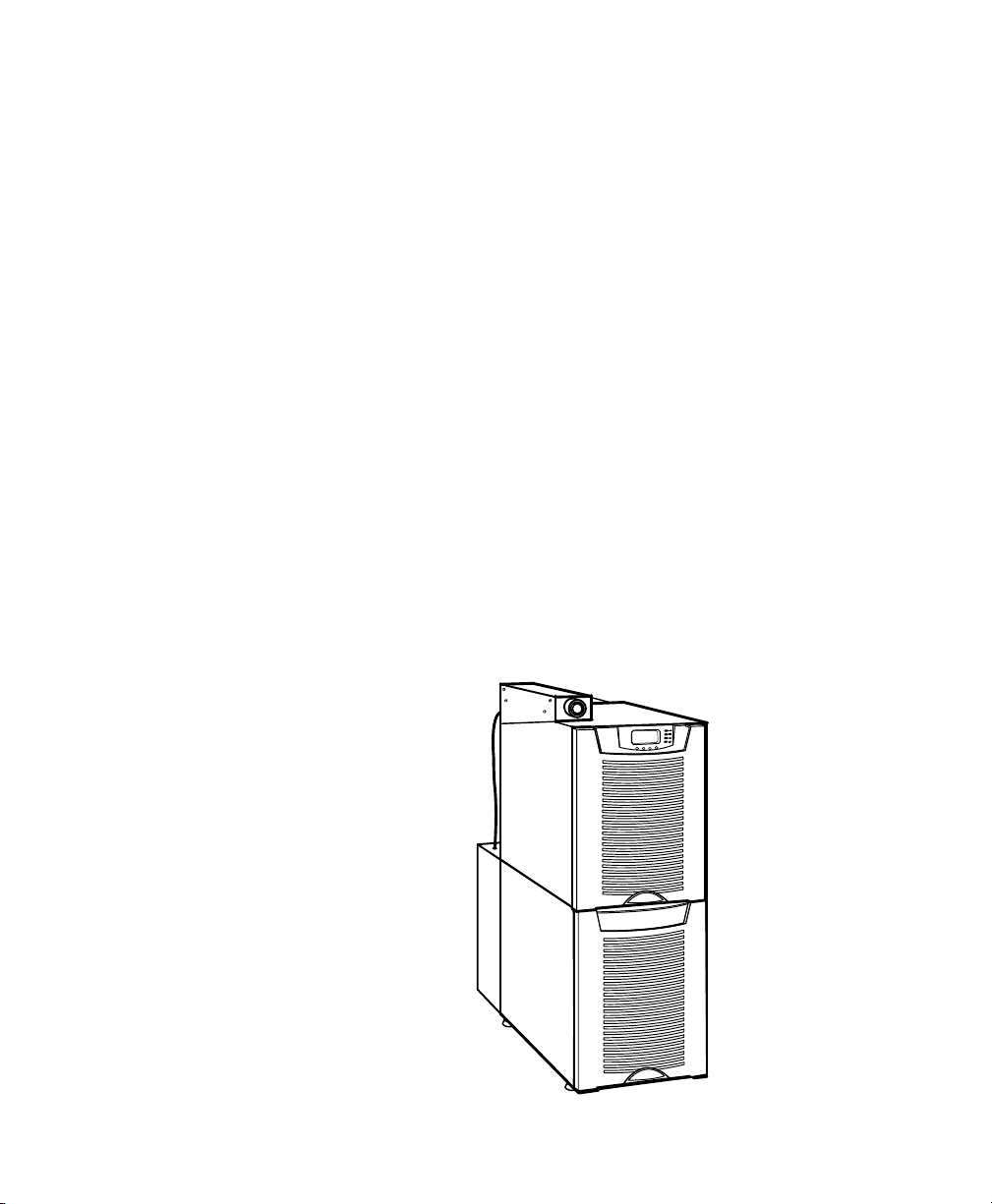
With the Eaton 9355-F47 Unirom UPS, you can safely eliminate the
effects of electrical line disturbances and guard the integrity of your
systems and equipment. Figure 1 shows the Eaton 9355-F47 Unirom
UPS.
Figure 1. The Eaton 9355-F47 Unirom UPS
Eaton 9355-F47 Unirom UPS (10/15 kVA) User's Guide S 164201642 Rev C www.eaton.com/powerquality
1

INTRODUCTION
Providing outstanding performance and reliability, the Eaton 9355-F47
Unirom UPS's unique benefits including the following:
S Online UPS design with pure sine wave output. The UPS filters and
regulates incoming AC power and provides consistent power to your
equipment without draining the battery.
S More wattage in less space with a 0.9 power factor—protecting more
equipment and leaving more room for expansion.
S Input current total harmonic distortion (THD) of less than five percent,
using active input power factor correction.
S ABM
®
technology that uses advanced battery management to
increase battery service life, optimize recharge time, and provide a
warning before the end of useful battery life.
S Advanced power management with the Software Suite CD for
controlled shutdowns and power monitoring.
S Emergency shutdown control through the remote emergency
power-off (REPO) port and emergency machine off (EMO) switch.
S Permanent lockout feature on the input and output breakers.
S Start-on-battery capability for powering up the UPS even if utility
power is not available (only when battery trays are installed).
S Standard communication options with a DB-9 serial port, relay output
contacts, and programmable signal inputs.
S Optional X-Slot
®
cards with enhanced communication capabilities for
increased power protection and control.
S Optional stabilizing bracket suitable for seismic applications.
The following options for the Eaton 9355-F47 Unirom UPS is available:
Remote Monitor Panel (RMP)
The optional RMP provides monitoring of the operational status and
alarm condition of the UPS from virtually any location within the facility.
You can install multiple RMPs at remote locations to increase your
monitoring capabilities.
Ultracapacitor Module
The optional ultracapacitor module provides momentary system backup
power for transient (0.1 to 3 second) power losses without the use of a
battery pack.
2
Eaton 9355-F47 Unirom UPS (10/15 kVA) User's Guide S 164201642 Rev C www.eaton.com/powerquality

Chapter 2 Safety Warnings
IMPORTANT SAFETY INSTRUCTIONS
SAVE THESE INSTRUCTIONS
This manual contains important instructions that you should follow during installation and
maintenance of the UPS and batteries or ultracapacitor. Please read all instructions before
operating the equipment and save this manual for future reference.
This UPS contains LETHAL VOLTAGES. All repairs and service should be performed by
AUTHORIZED SERVICE PERSONNEL ONLY. There are NO USER SERVICEABLE
PARTS inside the UPS.
S This UPS contains its own energy source (batteries or ultracapacitor). The UPS output
may carry live voltage even when the UPS is not connected to an AC supply.
S To reduce the risk of fire or electric shock, install this UPS in a temperature and humidity
controlled, indoor environment, free of conductive contaminants. Ambient temperature
must not exceed 40°C (104°F). Do not operate near water or excessive humidity (95%
maximum).
S To reduce the risk of fire, connect only to a circuit provided with 100 amperes maximum
branch circuit overcurrent protection in accordance with the National Electrical Code
(NEC®), ANSI/NFPA 70.
S Output overcurrent protection and disconnect switch must be provided by others.
D A N G E R
W A R N I N G
®
C A U T I O N
S The batteries or ultracapacitor can present a risk of electrical shock or burn from high
short-circuit current. Observe proper precautions. Servicing should be performed by
qualified service personnel knowledgeable of batteries and ultracapacitors and required
precautions. Keep unauthorized personnel away from batteries or ultracapacitors.
S Proper disposal of batteries or ultracapacitors is required. Refer to your local codes for
disposal requirements.
S Never dispose of batteries or ultracapacitors in a fire. Batteries or ultracapacitors may
explode when exposed to flame.
Eaton 9355-F47 Unirom UPS (10/15 kVA) User's Guide S 164201642 Rev C www.eaton.com/powerquality
3

SAFETY WARNINGS
Consignes de sécurité
Ce manuel comporte des instructions importantes que vous êtes invité à suivre lors de toute
procédure d'installation et de maintenance des batteries et de l'onduleur. Veuillez consulter
entièrement ces instructions avant de faire fonctionner l'équipement et conserver ce manuel
afin de pouvoir vous y reporter ultérieurement.
Cet onduleur contient des TENSIONS MORTELLES. Toute opération d'entretien et de
réparation doit être EXCLUSIVEMENT CONFIÉE A UN PERSONNEL QUALIFIÉ AGRÉÉ.
AUCUNE PIÈCE RÉPARABLE PAR L'UTILISATEUR ne se trouve dans l'onduleur.
S Cette onduleur possède sa propre source d'alimentation (batteries). Il est possible que les
S Pour réduire les risques d'incendie et de décharge électrique, installer l'onduleur
S Afin de réduire les risques d'incendie, ne raccordez qu'à un circuit muni d'une protection
S La protection de surintensité de sortie ainsi que le sectionneur doivent être fournis par
CONSIGNES DE SÉCURITÉ IMPORTANTES
CONSERVER CES INSTRUCTIONS
D A N G E R !
A V E R T I S S E M E N T !
prises de sortie soient sous tension même lorsque l'onduleur n'est pas connectée à une
alimentation CA.
uniquement à l'intérieur, dans un lieu dépourvu de matériaux conducteurs, où la
température et l'humidité ambiantes sont contrôlées. La température ambiante ne doit
pas dépasser 40 °C. Ne pas utiliser à proximité d'eau ou dans une atmosphère
excessivement humide (95 % maximum).
de surintensité du circuit de dérivation maximum de 100 ampères conformément au Code
Électrique National (National Electrical Code) des États-Unis, ANSI/NFPA 70.
des tiers.
A T T E N T I O N !
S Les batteries peuvent présenter un risque de choc électrique ou de brûlure provenant d'un
courant de court-circuit haute intensité. Observez les précautions appropriées. L'entretien
doit être réalisé par du personnel qualifié connaissant bien les batteries et les
précautions nécessaires. N'autorisez aucun personnel non qualifié à manipuler les
batteries.
S Une mise au rebut réglementaire des batteries est obligatoire. Consulter les règlements
en vigueur dans votre localité.
S Ne jamais jeter les batteries au feu. L'exposition aux flammes risque de les faire
exploser.
4
Eaton 9355-F47 Unirom UPS (10/15 kVA) User's Guide S 164201642 Rev C www.eaton.com/powerquality

Advertencias de Seguridad
INSTRUCCIONES DE SEGURIDAD IMPORTANTES
Este manual contiene instrucciones importantes que debe seguir durante la instalación y el
mantenimiento del SIE y de las baterías. Por favor, lea todas las instrucciones antes de poner
en funcionamiento el equipo y guarde este manual para referencia en el futuro.
Este SIE contiene VOLTAJES MORTALES. Todas las reparaciones y el servicio técnico deben
ser efectuados SOLAMENTE POR PERSONAL DE SERVICIO TÉCNICO AUTORIZADO. No hay
NINGUNA PARTE QUE EL USUARIO PUEDA REPARAR dentro del SIE.
S Este SIE contiene su propia fuente de energía (baterías). Los receptáculos de salida
pueden transportar voltaje activo aun cuando el SIE no esté conectado con una fuente
de CA.
S Para reducir el riesgo de incendio o de choque eléctrico, instale este SIE en un lugar
cubierto, con temperatura y humedad controladas, libre de contaminantes conductores.
La temperatura ambiente no debe exceder los 40°C. No trabaje cerca del agua o con
humedad excesiva (95% máximo).
S Para reducir el riesgo de incendio, realice la conexión únicamente hacia un circuito que
cuente con un máximo de 100 amperios de protección contra sobrecorriente de circuito
derivado, de acuerdo con el Código Eléctrico Nacional, ANSI/NFPA 70.
S La protección contra sobrecorriente de salida y el conmutador de desconexión debe
suministrarse por parte de terceros.
SAFETY WARNINGS
GUARDE ESTAS INSTRUCCIONES
P E L I G R O
A D V E R T E N C I A
P R E C A U C I Ó N
S Las baterías pueden constituir un riesgo de descarga eléctrica o quemaduras por
corriente alta de corto circuito. Adopte las precauciones debidas. Personal calificado de
servicio que conozca de baterías y esté al tanto de las precauciones requeridas debe
darle servicio al equipo. Mantenga al personal no autorizado alejado de las baterías.
S Es necesario desechar las baterías de un modo adecuado. Consulte las normas locales
para conocer los requisitos pertinentes.
S Nunca deseche las baterías en el fuego. Las baterías pueden explotar si se las expone a
la llama.
Eaton 9355-F47 Unirom UPS (10/15 kVA) User's Guide S 164201642 Rev C www.eaton.com/powerquality
5

SAFETY WARNINGS
6
Eaton 9355-F47 Unirom UPS (10/15 kVA) User's Guide S 164201642 Rev C www.eaton.com/powerquality

Chapter 3 Safety Overview
Review the Safety Warnings in the previous chapter and the safety
information in this chapter before working with the equipment.
Emergency Contacts
Fill in the following emergency contact information as soon as you install
the equipment at your site.
Safety Officer's Name:
Address
Phone (Home) (Work) (Pager)
Alternate Emergency Contact
Medical Officer's Name:
Address
Phone (Home) (Work) (Pager)
Alternate Emergency Contact
Personnel trained in
emergency medical
procedures:
Address
Phone (Home) (Work) (Pager)
Alternate Emergency Contact
Nearest Fire Extinguishers:
Nearest Fire Exits:
Further emergency contact information:
Unirom Electronics T-97246515015
# 52 Moshave Nahalal F-97246515793
P.O. Box 271 SUPPORT@UNIROM.CO.IL
ISRAEL ZIP 10600 AMIZUR@UNIROM.CO.IL
WWW.UNIROM.CO.IL
Eaton 9355-F47 Unirom UPS (10/15 kVA) User's Guide S 164201642 Rev C www.eaton.com/powerquality
7

SAFETY OVERVIEW
Training Requirements
Only trained personnel should service, maintain, or operate the
equipment. Training must include electrical safety guidelines.
Verify that personnel servicing, maintaining, and operating the
equipment have completed the following checklist before working with
the equipment:
1. Operator/engineer has read the user's guide.
2. Operator/engineer has received training and safety instructions,
including lockout/tagout procedures enforced at your site.
3. Operator/engineer knows emergency contact information.
4. Operator/engineer is aware of all potential hazards.
5. Operator/engineer can identify all relevant warning labels.
6. Operator/engineer knows location of all EMO/REPO buttons.
Hazards Summary
8
Eaton 9355-F47 Unirom UPS (10/15 kVA) User's Guide S 164201642 Rev C www.eaton.com/powerquality
Hazard alert labels and protective guards are used on potentially
hazardous areas of the equipment. These safeguards protect personnel
from potential exposure to hazards during normal operation and
maintenance. The user's guide provides procedures and information for
performing the required tasks safely.
Hazards associated with this equipment include:
S Hazardous energy isolation
S Electric shock hazards
S Toxic material hazard
S Falling object hazard
S Lifting and tip over hazards
The following sections describe each hazard.

Hazardous Energy Isolation
Table 1 lists the electrical hazardous energies present in the equipment.
Table 1. Hazardous Energy Isolation
Energy Type Isolation Point Danger Zone
SAFETY OVERVIEW
Method to Verify Absence of
Residual Energy
Electrical: 192 Vdc
Electrical: 208 Vac
CB2 battery circuit
breaker on upper rear
UPS housing
CB1 input circuit breaker
and CB3 output circuit
breaker
Interior of electronics module
(top section)
Interior of CB2 housing at rear
of UPS
Interior of electronics module
(top section)
UPS input/output terminal block
inside the lower circuit breaker
housing at the rear of the UPS
Measure CB2 secondary with a
DVM set for DC voltage.
Should read 0 volts.
Measure the secondary of both
CB1 and CB3 with a DVM set for
AC voltage.
Should read 0 volts.
Electric Shock Hazards
Hazardous electrical voltages up to 208 Vac are present inside the
equipment (see Table 1). There is no threat to personnel safety if the
equipment covers are in place and the safety features are not defeated.
The UPS includes batteries that should be replaced periodically. Always
handle batteries according to the procedures in the user's guide and in
accordance with the battery Safety Warnings in the user's guide.
Toxic Material Hazard
Do not open or mutilate the battery or batteries or ultracapacitor.
Released electrolyte is harmful to the skin and eyes. It may be toxic.
Dispose of used batteries or ultracapacitor according to your local codes.
Falling Object Hazard
Objects placed on top of the UPS could cause injury if they fall. Do not
place any object on top of the UPS.
Eaton 9355-F47 Unirom UPS (10/15 kVA) User's Guide S 164201642 Rev C www.eaton.com/powerquality
9
SAFETY OVERVIEW
EMO Pushbutton
35.2”
894 mm)
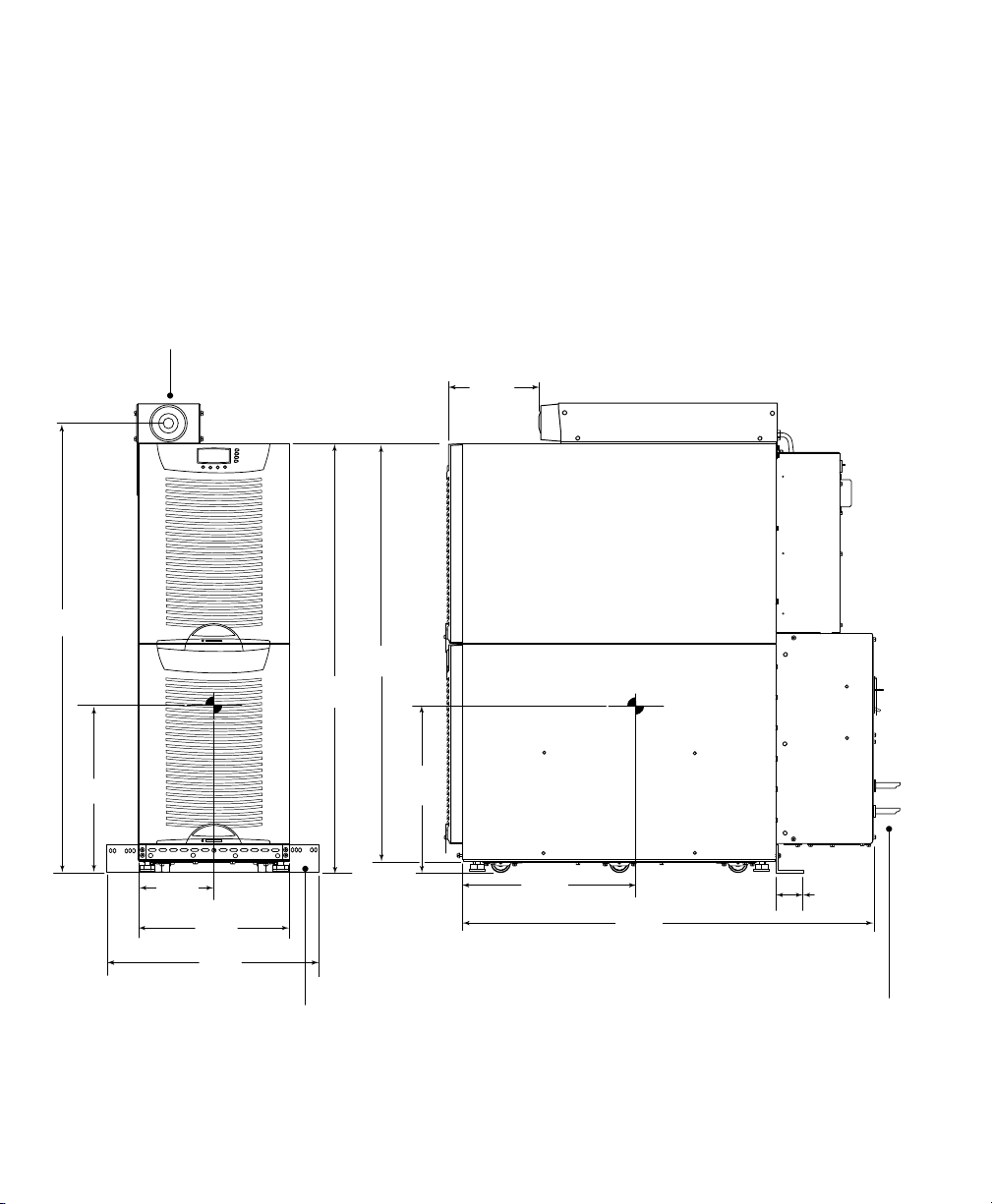
Lifting and Tip Over Hazards
The UPS is heavy (see Figure 2). Lifting may cause strain, and tip over
may cause severe injury or death. Use a forklift or pallet jack to lift or
move the UPS. Have at least two people present when lifting or moving
the UPS.
7.0”
(180 mm)
32.2”
(818 mm)
33.6”
(854 mm)
13.1”
(333 mm)
6.0”
(153 mm)
12.0”
(300 mm)
21.5”
(545 mm)
Stabilizing Bracket (on rear of UPS)
10
Eaton 9355-F47 Unirom UPS (10/15 kVA) User's Guide S 164201642 Rev C www.eaton.com/powerquality
13.1”
(333 mm)
13.6”
(345 mm)
33.5”
(850 mm)
Weight = 410 lb (186 kg)
Figure 2. Installed UPS Weight and Dimensions
2.0”
(50.8 mm)
Installed Conduit

Electrical Safety Features
The UPS is designed with safety features that protect personnel from
exposure to electrical hazards. Electrical safety features include:
S Coverings over all areas of hazardous voltage.
S Hazard alert labels on the exterior of any cover that shields areas of
hazardous voltage (see Figure 3).
S Wiring sizes, connections, and color codes that meet the
requirements of the NEC.
S Connectors have a ground that breaks last, makes first.
S Procedures in the user's guide include lockout/tagout steps for
personnel to follow while performing maintenance tasks.
Lockout/Tagout Procedures
Lockout/tagout devices and procedures help prevent an accidental
startup or a release of stored energy that could cause injury or
equipment damage.
SAFETY OVERVIEW
Follow all lockout/tagout procedures included in the user's guide and any
that are required at your site.
Modifying the equipment, overriding or defeating the devices, or failing
to follow the lockout/tagout procedures can cause injury or equipment
damage. Potentially lethal electrical voltages and currents are present in
the equipment and could cause shock, burn, or death.
Personal Protective Equipment
The UPS batteries require careful handling and the use of personal
protective equipment (PPE). Before handling batteries, put on rubber
gloves and boots, and remove watches, rings, or other metal objects.
Eaton 9355-F47 Unirom UPS (10/15 kVA) User's Guide S 164201642 Rev C www.eaton.com/powerquality
11
SAFETY OVERVIEW
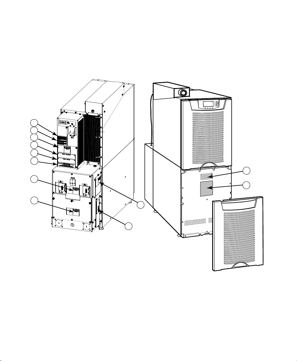
Safety Labels
1
2
3
4
5
6
7
Figure 3 and Table 2 describe the safety and other labels on the UPS.
11
12
12
8
10
9
Figure 3. UPS Label Locations
Eaton 9355-F47 Unirom UPS (10/15 kVA) User's Guide S 164201642 Rev C www.eaton.com/powerquality

Table 2. UPS Label Descriptions
Label in
Figure 3
Type of Label Description
1 Notice Equipment and class compliance notices
2 Hazard Alert Equipment and class compliance notices
3 Hazard Alert WARNING Hazardous Voltage Enclosed
4 Hazard Alert WARNING Hazardous Voltage Enclosed
5 Hazard Alert WARNING Hazardous Voltage Enclosed
6 Hazard Alert WARNING High Leakage Current
7 Hazard Alert WARNING Hazardous Voltage Enclosed
8 Hazard Alert WARNING Hazardous Voltage Enclosed
9 Hazard Alert WARNING Hazardous Voltage Enclosed
10 Hazard Alert WARNING Hazardous Voltage Enclosed
11 Hazard Alert CAUTION Battery caution, battery rating, battery model number
12 Hazard Alert WARNING Hazardous Voltage Enclosed
SAFETY OVERVIEW
Eaton 9355-F47 Unirom UPS (10/15 kVA) User's Guide S 164201642 Rev C www.eaton.com/powerquality
13

SAFETY OVERVIEW
14
Eaton 9355-F47 Unirom UPS (10/15 kVA) User's Guide S 164201642 Rev C www.eaton.com/powerquality

Chapter 4 UPS Setup
This chapter describes:
S Equipment inspection
S Floor loading and clearances
S Unloading the UPS
The instructions are intended for the chief operator/system supervisor,
electrical consultants, and installation electricians. Local regulations and
electrical code must be followed during the UPS installation.
Before beginning work, review Chapter 3, “Safety Overview,” and be
familiar with all equipment safety features and precautions.
Inspecting the Equipment
If any equipment has been damaged during shipment, keep the shipping
and packing materials for the carrier or place of purchase and file a claim
for shipping damage. If you discover damage after acceptance, file a
claim for concealed damage.
To file a claim for shipping damage or concealed damage: 1) File with
the carrier within 15 days of receipt of the equipment; 2) Send a copy of
the damage claim within 15 days to your service representative.
NOTE The UPS is normally shipped without batteries or ultracapacitor module installed.
NOTE Check the battery recharge date on the packaging label. If the date has expired and
the batteries were never recharged, do not use the UPS. Contact your service representative.
Eaton 9355-F47 Unirom UPS (10/15 kVA) User's Guide S 164201642 Rev C www.eaton.com/powerquality
15
UPS SETUP
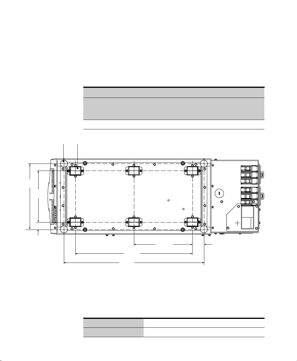
Floor Loading
When planning the installation, consider the UPS weight for floor
loading. The strength of the installation surface must be adequate for
point and distributed loadings. The approximate weights are shown in
the following table. Figure 4 shows the leveling feet and casters.
Standard Model Floor Loadings
Leveling Feet (4x)
10.43”
(265 mm)
8.15”
(207 mm)
1.14”
(29 mm)
Eaton 9355-F47
Unirom
Maximum Weight
(without Batteries or
Ultracapacitor)
Maximum Weight
(with Both Battery
Trays or Ultracapacitor)
UPS 190 lb (86.2 kg) 410 lb (186 kg) 103 (7.3)
Casters (6x)
9.31”
18.62”
(473 mm)
22.28”
(566 mm)
(236.5 mm)
(46.5 mm)
Figure 4. Leveling Feet and Casters
1.83”
Point Loading
2
lb/in
(kg/cm2)
Clearances
16
Eaton 9355-F47 Unirom UPS (10/15 kVA) User's Guide S 164201642 Rev C www.eaton.com/powerquality
The following clearances are recommended for the Eaton 9355-F47
Unirom UPS:
From Front of Cabinet 36” (91.4 cm) working space
From Back of Cabinet 6” (15.2 cm)
Unloading the UPS
UPS SETUP
NOTE Retain the front panel of the UPS packing crate to use as a ramp when unloading the
UPS from the pallet.
The following tools are required for unloading the UPS:
S Forklift or pallet jack
S 15 mm wrench or socket
S 7 mm nut driver or socket
C A U T I O N
The UPS is heavy (see page 16). Verify that the forklift or pallet jack is rated to handle the
weight of the UPS. Unloading the UPS requires at least two people to safely remove the UPS
from the pallet.
The UPS is shipped bolted to a wooden pallet and protected with outer
protective packaging material.
To unload the UPS:
1. Carefully inspect the outer packaging for evidence of damage
during transit.
2. Use a forklift or pallet jack to move the packaged UPS to the
installation site, or as close as possible, before unpacking. Insert
the forklift or pallet jack forks between the skids on the bottom of
the pallet.
3. Set the pallet on a firm, level, surface, allowing a minimum
clearance of 10 ft (3m) on each side for removing the UPS from the
pallet.
4. Remove the protective covering from the UPS.
5. Remove the packing material, and discard or recycle in a
responsible manner.
NOTE If installation is delayed, protect the unpacked UPS from moisture, dust, and other
harmful contaminants. Failure to store and protect the UPS properly may void your warranty.
Eaton 9355-F47 Unirom UPS (10/15 kVA) User's Guide S 164201642 Rev C www.eaton.com/powerquality
17
UPS SETUP
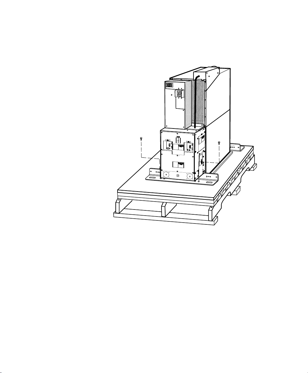
6. Remove the two M10 bolts securing the rear stabilizing bracket to
the pallet (see Figure 5).
M10 Bolt
M10 Bolt
Figure 5. Removing the Rear Stabilizing Bracket Bolts
18
Eaton 9355-F47 Unirom UPS (10/15 kVA) User's Guide S 164201642 Rev C www.eaton.com/powerquality
UPS SETUP
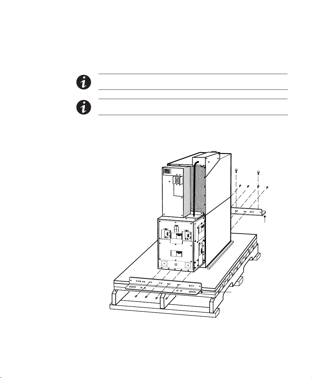
7. Remove the four M4 screws securing the rear stabilizing bracket to
the cabinet rear panel and remove the bracket (see Figure 6). Retain
the hardware for later use.
NOTE Be sure to retain the rear stabilizing bracket and hardware for later re-assembly onto
the UPS.
NOTE Hold the UPS so that the bolts can be removed easily without the UPS rolling
backward.
8. Remove the two M10 bolts securing the front shipping bracket to
the pallet. Remove the four M4 screws securing the bracket to the
cabinet front panel and remove the bracket. See Figure 6.
M10 Bolts
M4 Screws
(under CB box)
Rear Stabilizing Bracket
Figure 6. Removing the Brackets
Eaton 9355-F47 Unirom UPS (10/15 kVA) User's Guide S 164201642 Rev C www.eaton.com/powerquality
M4 Screws
Front
Shipping
Bracket
19

UPS SETUP
9. Place the front crate panel, retained from the UPS packing crate,
onto the skids at the back of the pallet. Verify that the flat side of
the crate panel is facing up, with the beveled edge pointing away
from the pallet.
Secure the crate panel to the skids with two bolts. See Figure 7.
20
Figure 7. Unloading the UPS
10. Slowly roll the UPS toward the rear of the pallet. If needed, adjust
the leveling feet so that the UPS will roll.
Eaton 9355-F47 Unirom UPS (10/15 kVA) User's Guide S 164201642 Rev C www.eaton.com/powerquality
UPS SETUP
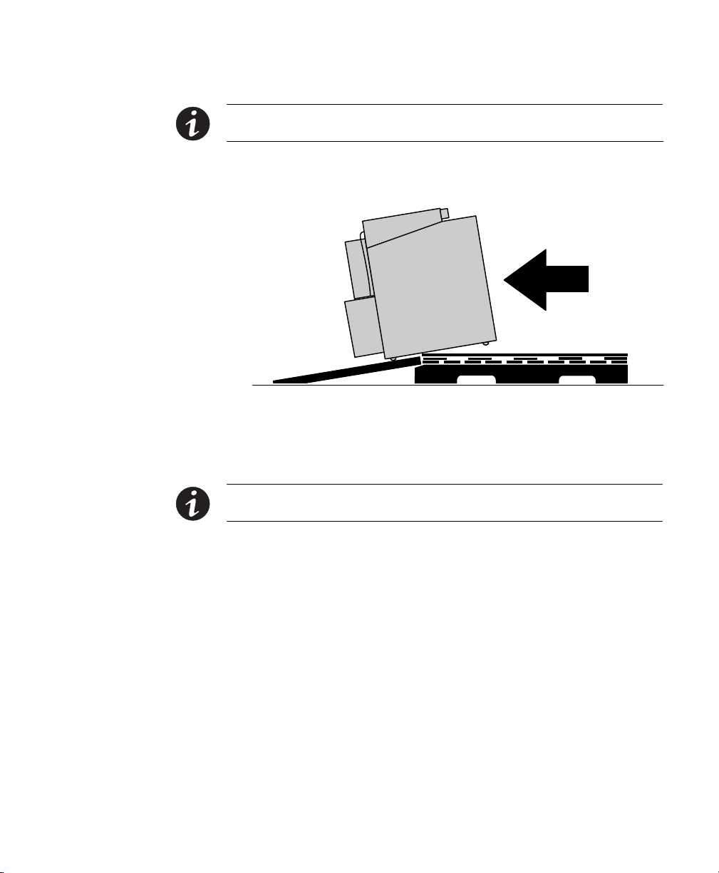
NOTE In the following step, the crate panel will act as a ramp. Be sure to support the front
and back of the UPS when rolling it off the pallet to prevent tipping.
11. With the UPS supported, slowly roll the UPS down the ramp until
the UPS is clear of the pallet and ramp (see Figure 8).
Figure 8. Clearing the Pallet and Ramp
12. Roll the UPS to the desired location.
13. Continue to the following chapter, “UPS Installation.”
NOTE If installation is delayed, protect the unpacked UPS from moisture, dust, and other
harmful contaminants. Failure to store and protect the UPS properly may void your warranty.
Eaton 9355-F47 Unirom UPS (10/15 kVA) User's Guide S 164201642 Rev C www.eaton.com/powerquality
21

UPS SETUP
22
Eaton 9355-F47 Unirom UPS (10/15 kVA) User's Guide S 164201642 Rev C www.eaton.com/powerquality
Chapter 5 UPS Installation
The Eaton 9355-F47 Unirom UPS has the following power connections:
S 3‐phase (L1, L2, and L3), neutral, and ground connection for
rectifier/bypass input
S 3‐phase (L1, L2, and L3), neutral, and ground connection for load
output
The nominal input/output voltages are 120/208 Vac.
Input and output overcurrent protection and disconnect switches must
be provided by others.
Figure 12 on page 29 shows the oneline diagram.
Only qualified service personnel (such as a licensed electrician) should perform the UPS
installation and initial startup. Risk of electrical shock.
To hardwire the UPS:
1. Verify that the electrical connections to the installation site have
been properly installed.
W A R N I N G
2. A wall-mounted, user‐supplied, readily‐accessible disconnection
device must be incorporated in the input wiring.
Compare the circuit breaker ratings to the specifications in Table 3
on page 25.
NOTE To accommodate the feature of easy system expandability, it is recommended that
initial installation of the Eaton 9355-F47 Unirom UPS contain wiring to support the maximum
capacity of the UPS.
3. Notify others working in the immediate area that the UPS is under
maintenance control.
4. Switch off utility power to the distribution point where the UPS will
be connected. Be absolutely sure there is no power.
Eaton 9355-F47 Unirom UPS (10/15 kVA) User's Guide S 164201642 Rev C www.eaton.com/powerquality
23
UPS INSTALLATION
5. Determine your equipment's grounding requirements according to
your local electrical code.
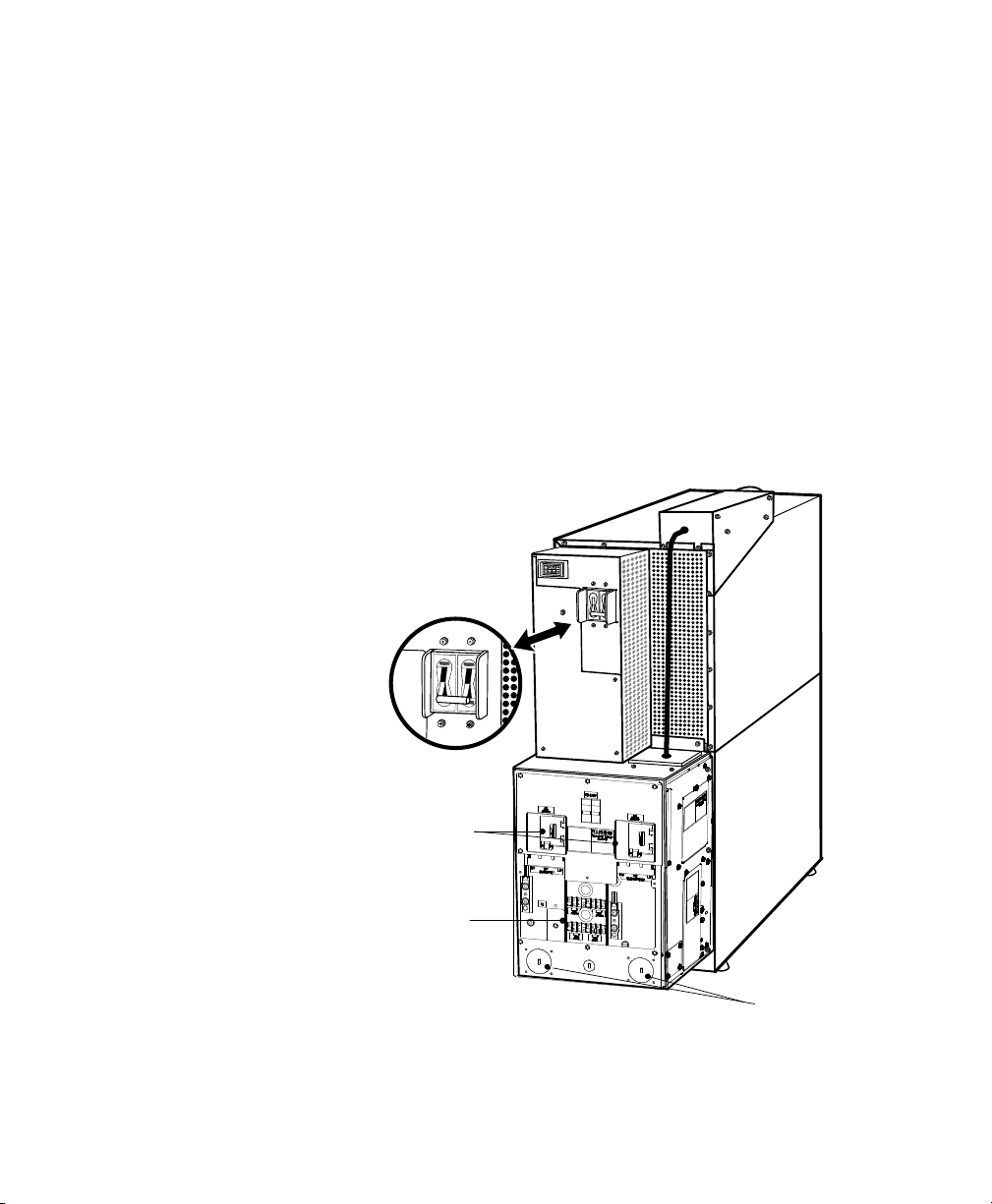
6. Verify that the UPS battery circuit breaker is in the OFF position
(see Figure 9).
7. Verify that the input and output circuit breakers are in the OFF
position (see Figure 9).
8. Using customer-provided locks, lock the input and output circuit
breakers in the OFF position. Display a DO NOT OPERATE tag,
completed with your name, the date, and the time of locking.
9. Verify the absence of hazardous energy according to Table 1 on
page 9.
Battery Circuit
Breaker
24
Input and Output
Circuit Breakers
Control Wiring
Terminal Board
Conduit
Knockouts
Figure 9. UPS Rear View
10. Remove the UPS wiring access cover and retain (see Figure 9).
Eaton 9355-F47 Unirom UPS (10/15 kVA) User's Guide S 164201642 Rev C www.eaton.com/powerquality
 Loading...