

Eaton 9315, 9390, 9395 Installation And Operation Manual

Eaton 9315/9390/9395
Fixed Master Sync Control
Fixed Master Sync Control
Installation and Operation Manual
Installation and Operation Manual
®

IMPORTANT SAFETY INSTRUCTIONS
SAVE THESE INSTRUCTIONS
This manual contains important instructions that you should follow during installation and maintenance of the UPS and batteries. Please
read all instructions before operating the equipment and save this manual for future reference.
CONSIGNES DE SÉCURITÉ IMPORTANTES
CONSERVER CES INSTRUCTIONS
Ce manuel comporte des instructions importantes que vous êtes invité à suivre lors de toute procédure d'installation et de maintenance
des batteries et de l'onduleur. Veuillez consulter entièrement ces instructions avant de faire fonctionner l'équipement et conserver ce
manuel afin de pouvoir vous y reporter ultérieurement.
Eaton and X-Slot are registered trademarks of Eaton Corporation or its subsidiaries and affiliates. National Electric Code and NEC are a
registered trademarks of National Fire Protection Association, Inc. All other trademarks are property of their respective companies.
ECopyright 2005–2011 Eaton Corporation, Raleigh, NC, USA. All rights reserved. No part of this document may be reproduced in any
way without the express written approval of Eaton Corporation.

Table of Contents
1 Introduction 1-1............................................................................
1.1 Conventions Used in This Manual 1-3..........................................................................
1.2 Safety Warnings 1-3......................................................................................
1.3 For More Information 1-4...................................................................................
1.4 Getting Help 1-4.........................................................................................
2 Installation Plan and Unpacking 2-1............................................................
2.1 Creating an Installation Plan 2-1.............................................................................
2.2 Preparing the Site 2-1.....................................................................................
2.2.1 Environmental and Installation Considerations 2-1............................................................
2.2.2 Eaton Fixed Master Sync Control and Master Interface Wiring Preparation 2-6........................................
2.3 Inspecting and Unpacking the Eaton Fixed Master Sync Control or Master Interface 2-6......................................
3 Installation 3-1.............................................................................
3.1 Installation 3-2..........................................................................................
3.2 Installation and Wiring with an Eaton 9315 UPS 3-5................................................................
3.3 Installation and Wiring with an Eaton 9390 UPS 3-15................................................................
3.4 Installation and Wiring with an Power Xpert 9395 UPS 3-19...........................................................
4 Operation 4-1..............................................................................
4.1 Startup for UPS Systems Equipped with an Eaton Fixed Master Sync Control 4-1...........................................
4.2 Understanding Eaton Fixed Master Sync Control Operation 4-1........................................................
4.3 Operation 4-3...........................................................................................
4.4 Maintenance Operations 4-4................................................................................
5 Warranty 5-1..............................................................................
Eaton 9315/9390/9395 Fixed Master Sync Control Installation and Operation Manual S P-164000023 Rev 1 www.eaton.com/powerquality
i

TABLE OF CONTENTS
List of Figures
Figure 1‐1. Eaton Fixed Master Sync Control 1-1.................................................................
Figure 1‐2. Eaton Fixed Master Sync Control with Door Open 1-2......................................................
Figure 1‐3. Eaton Sync Control Master Interface Panel 1-2..........................................................
Figure 2‐1. Eaton Fixed Master Sync Control Dimensions – Front View 2-2...............................................
Figure 2‐2. Eaton Fixed Master Sync Control Dimensions – Side Views 2-3...............................................
Figure 2‐3. Eaton Master Interface Enclosure Dimensions - Front View 2-4...............................................
Figure 2‐4. Eaton Master Interface Enclosure Dimensions - Side. Rear, and Bottom Views 2-5.................................
Figure 3‐1. Fixed Master Sync Control with Master Interface Enclosure Functional Diagram 3-1................................
Figure 3‐2. Typical Eaton Fixed Master Sync Control Control Wiring Termination Locations 3-2................................
Figure 3‐3. Eaton Fixed Master Sync Control TB1 Terminal Block Detail 3-3..............................................
Figure 3‐4. Typical Control Wiring Termination Locations for Eaton Master Interface Enclosure 3-4.............................
Figure 3‐5. TB6 Terminal Block Detail (All Systems) 3-10............................................................
Figure 3‐6. Fixed Master Sync Control Interface Location for 30-80 kVA Single Module 9315 UPS System 3-10......................
Figure 3‐7. Fixed Master Sync Control Interface Location for 100-160 kVA Single Module 9315 UPS System 3-11....................
Figure 3‐8. Fixed Master Sync Control Interface Locations for 200-300 kVA Single Module 9315 UPS System 3-12...................
Figure 3‐9. Fixed Master Sync Control Interface Location for 400-500 kVA Single Module 9315 UPS System 3-13....................
Figure 3‐10. Fixed Master Sync Control Interface Location for 750 kVA Single Module 9315 UPS System 3-14......................
Figure 3‐11. Eaton 9390 UPS (40–80 kVA) Interface Locations for Eaton Fixed Master Sync Control 3-17...........................
Figure 3‐12. Eaton 9390 UPS (100–160 kVA) Interface Locations for Eaton Fixed Master Sync Control 3-18.........................
Figure 3‐13. TB6 Terminal Block Detail 3-18.....................................................................
Figure 3‐14. TB6 Terminal Block Detail (All Systems) 3-21............................................................
Figure 3‐15. Power Xpert 9395 UPS (225–275 kVA) Interface Locations for Eaton Fixed Master Sync Control 3-21....................
Figure 3‐16. Power Xpert 9395 UPS and Plus 1 UPS (450–550 kVA) Interface Locations for Eaton Fixed Master Sync Control 3-22.........
Figure 3‐17. Power Xpert 9395 UPS and Plus 1 UPS (650–825 kVA) Interface Locations for Eaton Fixed Master Sync Control 3-23.........
Figure 3‐18. Power Xpert 9395 UPS (1000–1100 kVA) Interface Locations for Eaton Fixed Master Sync Control 3-24..................
Figure 3‐19. Relay Interface Card 3-25.........................................................................
Figure 3‐20. Relay Interface Card Terminals 3-25..................................................................
Figure 4‐1. Synchronization Reference Control 4-2................................................................
Figure 4‐2. Eaton Fixed Master Sync Control Controls and Indicators 4-3................................................
ii
Eaton 9315/9390/9395 Fixed Master Sync Control Installation and Operation Manual S P-164000023 Rev 1 www.eaton.com/powerquality

Chapter 1 Introduction
Figure
The Eaton® Sync Control maintains the critical load outputs of two separate single
UPS systems in synchronization. Use of the Eaton Fixed Master Sync Control
provides the uninterrupted transfer of the load from one load bus to another by
means of downstream, dual-source, solid-state, transfer switches. Without the load
sync option, the two system output (critical load) buses could become out of phase
with each other. This condition occurs when suitable bypass sources are not available
or when the bypass sources feeding each system are not in sync with each other.
Examples of this condition are two systems supplied by separate generator sets, or
the bypass sources for the two systems are lost.
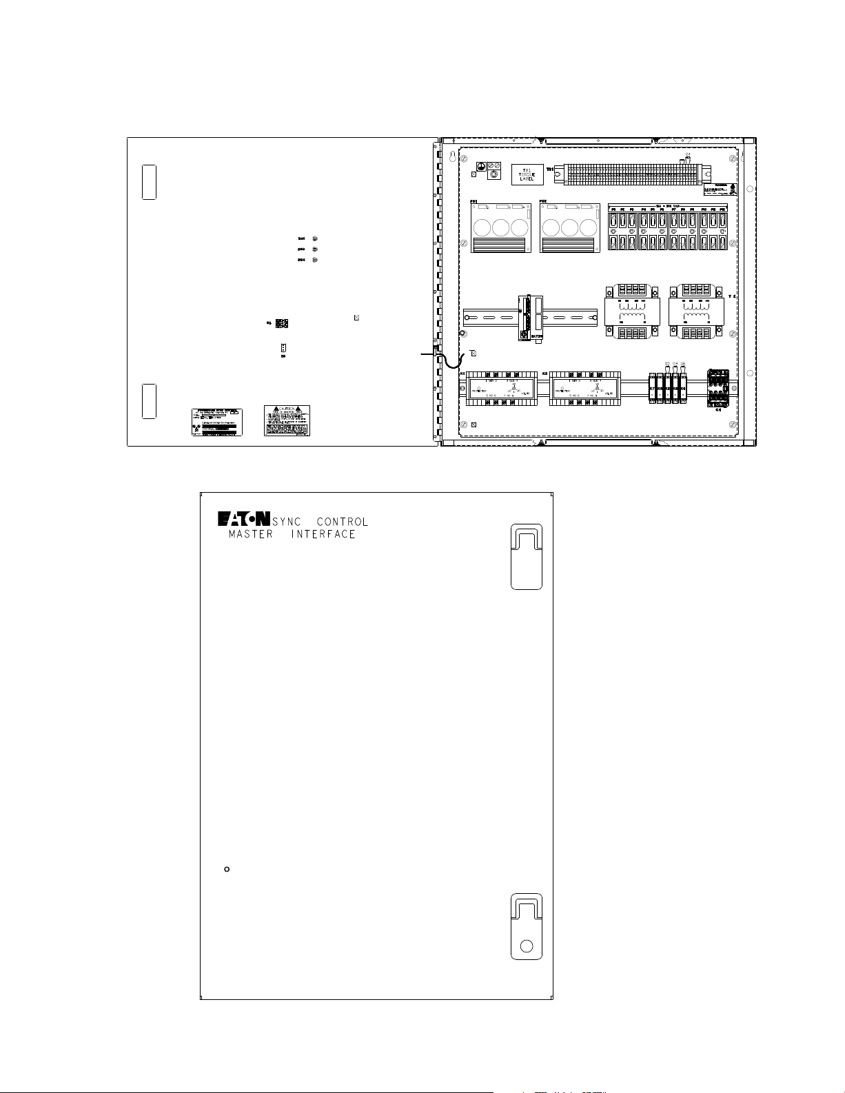
The additional use of the optional Sync Control Master Interface unit allows multiple
systems to be synched using one Sync Control unit.
Figure 1‐1 shows the front view and Figure 1‐2 shows the interior view of the Eaton
Fixed Master Sync Control. Figure 1‐3 shows the optional Sync Control Master
Interface unit.
Figure 1‐1. Eaton Fixed Master Sync Control
Eaton 9315/9390/9395 Fixed Master Sync Control Installation and Operation Manual S P-164000023 Rev 1 www.eaton.com/powerquality
1-1
INTRODUCTION
Figure 1‐2. Eaton Fixed Master Sync Control with Door Open
1-2
Figure 1‐3. Eaton Sync Control Master Interface Panel
Eaton 9315/9390/9395 Fixed Master Sync Control Installation and Operation Manual S P-164000023 Rev 1 www.eaton.com/powerquality
1.1 Conventions Used in This Manual
This manual uses these type conventions:
S Bold type highlights important concepts in discussions, key terms in procedures,
and menu options, or represents a command or option that you enter at a prompt.
S Italic type highlights notes and new terms where they are defined.
S Screen type represents information that appears on the screen or LCD.
Icon Description
Information notes call attention to important features or instructions.
[Keys] Brackets are used when referring to a specific key, such as [Enter] or [Ctrl].
In this manual, the term UPS refers only to the UPS cabinet and its internal elements.
The term UPS system refers to the entire power protection system – the UPS
cabinet, the battery cabinet, and options or accessories installed.
INTRODUCTION
1.2 Safety Warnings
IMPORTANT SAFETY INSTRUCTIONS
SAVE THESE INSTRUCTIONS
This manual contains important instructions that should be followed during installation and maintenance of
the UPS and batteries. Please read all instructions before operating the equipment and save this manual for
future reference.
The UPS cabinet is designed for industrial or computer room applications, and contains safety shields behind
the doors. However, the UPS system is a sophisticated power system and should be handled with care.
D A N G E R
This UPS contains LETHAL VOLTAGES. All repairs and service should be performed by AUTHORIZED
SERVICE PERSONNEL ONLY. There are NO USER SERVICEABLE PARTS inside the UPS.
W A R N I N G
S The UPS system contains its own energy source (batteries). The output terminals may carry live voltage
even when the UPS is disconnected from an AC source.
S To reduce the risk of fire or electric shock, install this UPS in a temperature and humidity controlled,
indoor environment, free of conductive contaminants. Ambient temperature must not exceed 40C
(104F). Do not operate near water or excessive humidity (95% maximum). The system is not intended for
outdoor use.
S Ensure all power is disconnected before performing installation or service.
C A U T I O N
S Keep the UPS doors closed to ensure proper cooling airflow and to protect personnel from dangerous
voltages inside the unit.
S Do not operate the UPS system close to gas or electric heat sources.
S The operating environment should be maintained within the parameters stated in this manual.
S Keep surroundings uncluttered, clean, and free from excess moisture.
S Observe all DANGER, CAUTION, and WARNING notices affixed to the inside and outside of the
equipment.
Eaton 9315/9390/9395 Fixed Master Sync Control Installation and Operation Manual S P-164000023 Rev 1 www.eaton.com/powerquality
1-3

INTRODUCTION
1.3 For More Information
Refer to the following manuals for additional information:
S Eatont 9315 30-500 kVA UPS Installation and Operation Manual
S Eatont 9315 750 kVA UPS Installation and Operation Manual
S Eaton 9390 UPS (40–80 kVA) Installation and Operation Manual
S Eaton 9390 UPS (100–160 kVA) Installation and Operation Manual
S Power Xpert 9395 UPS (225–275 kVA) Installation and Operation Manual
S Power Xpert 9395 Plus 1 UPS (225–275 kVA) Installation and Operation Manual
S Power Xpert 9395 UPS (300 kVA) Installation and Operation Manual
S Power Xpert 9395 550/275 UPS (225–550 kVA) Installation and Operation
Manual
S Power Xpert 9395 UPS and Plus 1 UPS (450–550 kVA) Installation and
Operation Manual
S Power Xpert 9395 UPS and Plus 1 UPS (650–825 kVA) Installation and
Operation Manual
S Power Xpert 9395 UPS (1000–1100 kVA) Installation and Operation Manual
1.4 Getting Help
These manuals describe:
S UPS cabinet, optional components, and accessory installation instructions,
including site preparation, planning for installation, and wiring and safety
information. Detailed illustrations of cabinets and optional accessories with
dimensional and connection point drawings are provided.
S UPS operation, including UPS cabinet controls, functions of the UPS, standard
features and optional accessories, procedures for starting and stopping the UPS,
and information about maintenance and responding to system events.
S Communication capabilities of the UPS system.
Visit www.eaton.com/powerquality or contact Eaton service representative for
information on how to obtain copies of these manuals.
If help is needed with any of the following:
S Scheduling initial startup
S Regional locations and telephone numbers
S A question about any of the information in this manual
S A question this manual does not answer
Please call the Help Desk at:
1-4
United States:
Canada: 1-800-461-9166 ext 260
All other countries: Call your local service representative
Eaton 9315/9390/9395 Fixed Master Sync Control Installation and Operation Manual S P-164000023 Rev 1 www.eaton.com/powerquality
1-800-843-9433 or 1-919-870-3028

Chapter 2 Installation Plan and Unpacking
Figure
The Eaton Fixed Master Sync Control is shipped as a separate item and can be
mounted on any surface that can safely bear its weight. See paragraph 2.2 for weight,
dimensions, and wiring preparation.
2.1 Creating an Installation Plan
Before installing the UPS system, read and understand how this manual applies to the
system being installed. Use the procedures and illustrations in the following chapters
to create a logical plan for installing the system.
NOTE Startup and operational checks must be performed by an authorized Eaton Customer Service
Engineer, or the warranty terms as specified on page 5-1 become void. This service is offered as part of the
sales contract for the UPS. Contact service in advance (usually a two-week notice is required) to reserve a
preferred startup date.
2.2 Preparing the Site
For the Eaton Fixed Master Sync Control to operate at peak efficiency, the installation
site should meet the environmental parameters outlined in the applicable Eaton 9315,
Eaton 9390 or Power Xpert 9395 UPS installation and operation manual listed in
paragraph 1.3.
2.2.1 Environmental and Installation Considerations
The life of the Eaton Fixed Master Sync Control is adversely affected if the system is
not installed in a temperature and humidity controlled indoor area free of conductive
contaminants.
Failure to follow guidelines may void your warranty.
The UPS equipment operating environment must meet the weight requirements
shown in Table 2‐1 and the size requirements shown in Figure 2‐1 and Figure 2‐2.
Dimensions are in millimeters (inches).
Table 2‐1. Equipment Weight
Model
Shipping Installed
Eaton Fixed Master Sync Control 45.4 (100) 36.3 (80)
Eaton Master Interface 17.25 (38) 15.0 (33)
Weight
kg (lb)
Eaton 9315/9390/9395 Fixed Master Sync Control Installation and Operation Manual S P-164000023 Rev 1 www.eaton.com/powerquality
2-1

INSTALLATION PLAN AND UNPACKING
Four Mounting Holes
in Rear of Panel
66.27
[26.09]
61.18
[24.09]
3.18
[1.25]
56.9
[22.0]
64.77
[25.5]
2-2
FRONT VIEW
Dimensions are in millimeters [inches].
Figure 2‐1. Eaton Fixed Master Sync Control Dimensions – Front View
Eaton 9315/9390/9395 Fixed Master Sync Control Installation and Operation Manual S P-164000023 Rev 1 www.eaton.com/powerquality
INSTALLATION PLAN AND UNPACKING
20.32
[8.0]
Knockout Holes for
1-Inch Conduit
5.08
[2.0]
6.35
[2.5]
6.35
[2.5]
LEFT SIDE VIEW
RIGHT SIDE VIEW
Dimensions are in millimeters [inches].
Figure 2‐2. Eaton Fixed Master Sync Control Dimensions – Side Views
Eaton 9315/9390/9395 Fixed Master Sync Control Installation and Operation Manual S P-164000023 Rev 1 www.eaton.com/powerquality
2-3
INSTALLATION PLAN AND UNPACKING
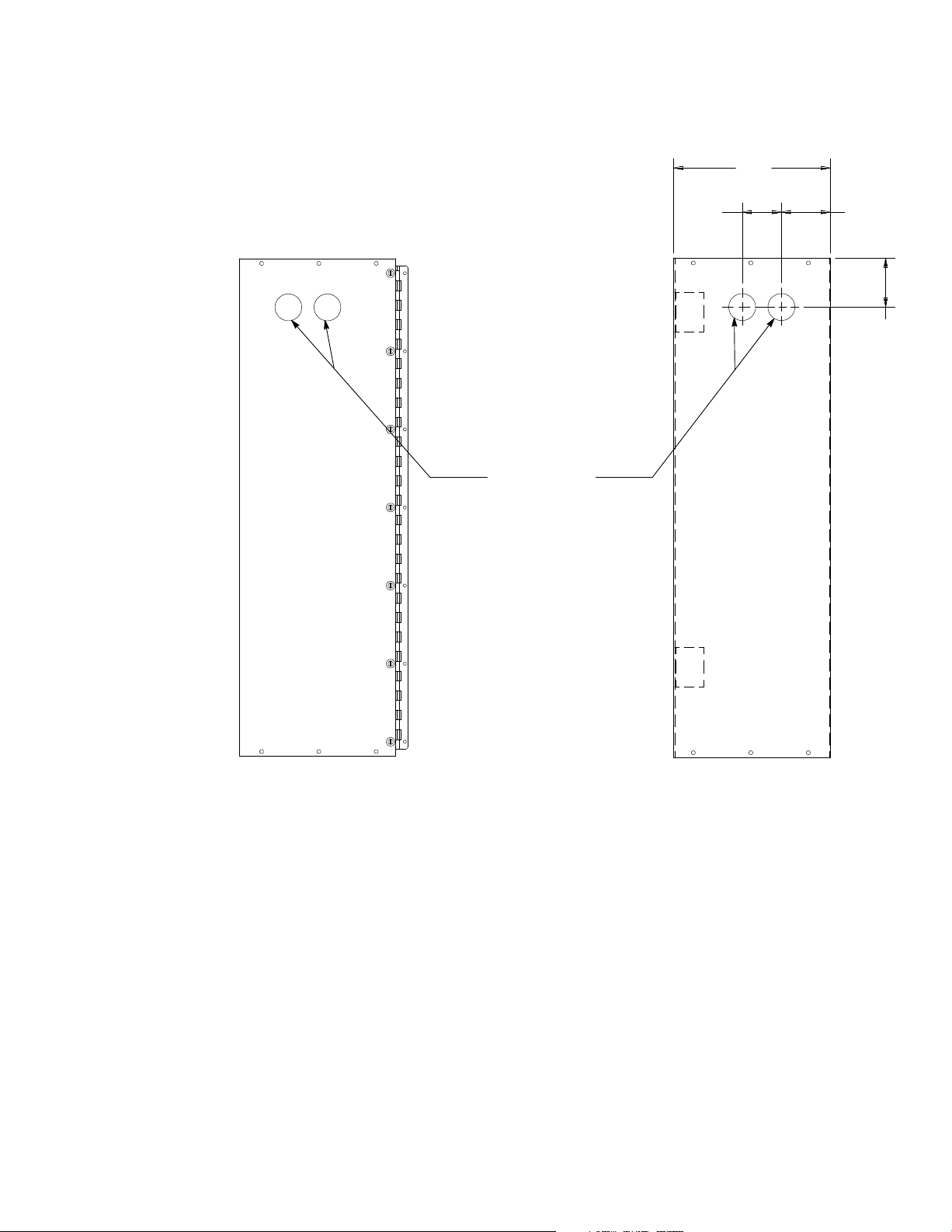
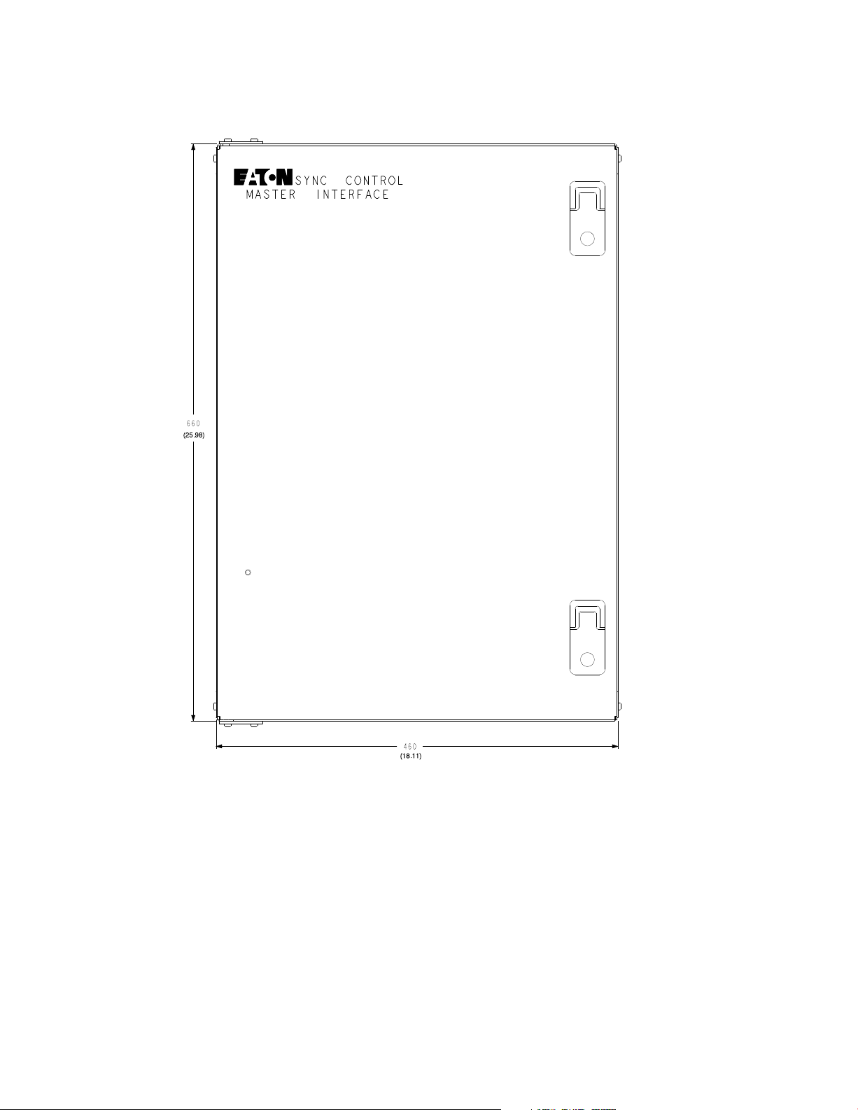
2-4
DIMENSIONS ARE IN MILLIMETERS [INCHES]
Figure 2‐3. Eaton Master Interface Enclosure Dimensions - Front View
Eaton 9315/9390/9395 Fixed Master Sync Control Installation and Operation Manual S P-164000023 Rev 1 www.eaton.com/powerquality
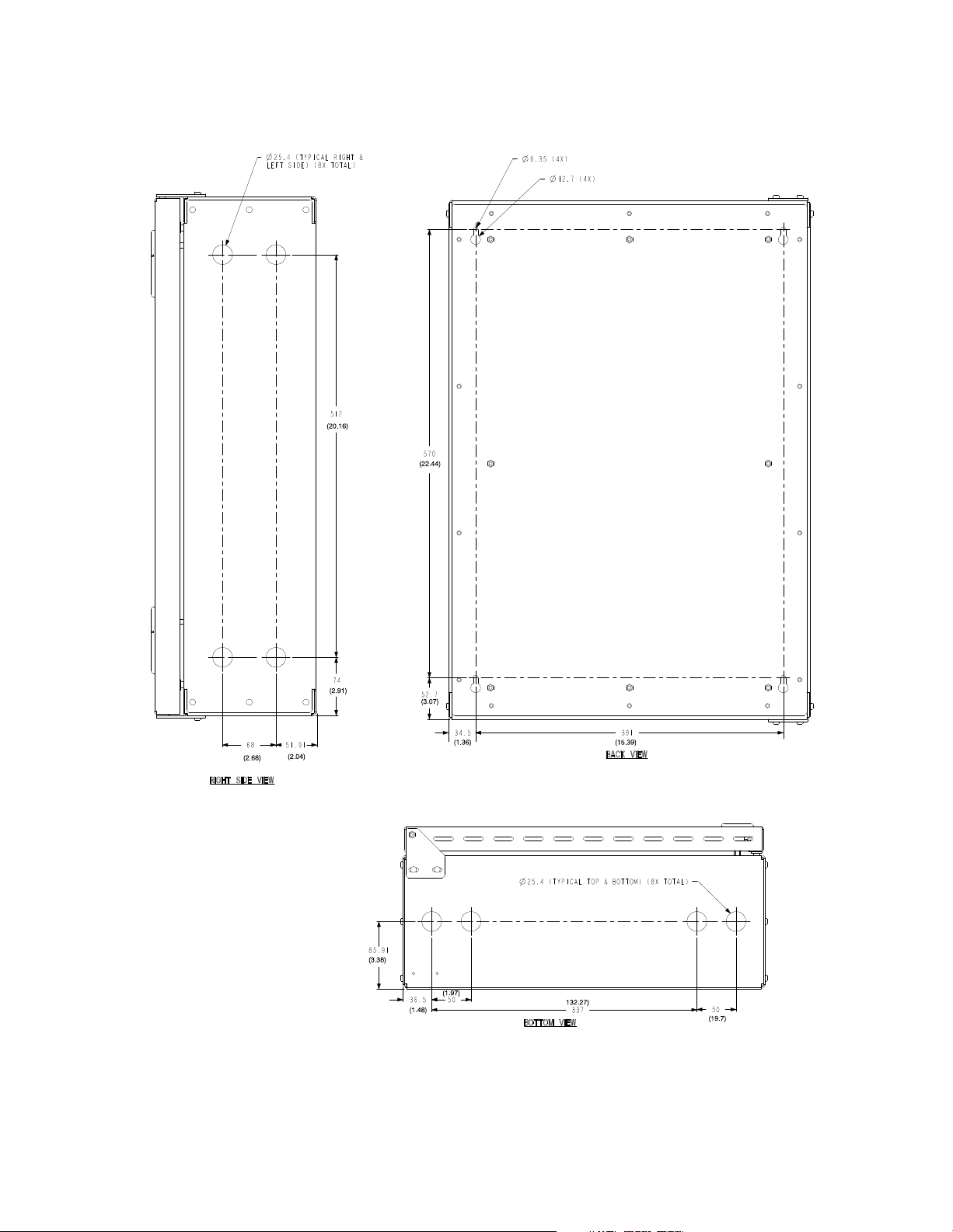
INSTALLATION PLAN AND UNPACKING
(Showing keyhole mounting slots)
DIMENSIONS ARE IN MILLIMETERS [INCHES]
Figure 2‐4. Eaton Master Interface Enclosure Dimensions - Side. Rear, and Bottom Views
Eaton 9315/9390/9395 Fixed Master Sync Control Installation and Operation Manual S P-164000023 Rev 1 www.eaton.com/powerquality
2-5

INSTALLATION PLAN AND UNPACKING
2.2.2 Eaton Fixed Master Sync Control and Master Interface Wiring Preparation
Read and understand the following notes while planning and performing the
installation:
S Refer to national and local electrical codes for acceptable external wiring practices.
S Material and labor for external wiring requirements are to be provided by
designated personnel.
S For external wiring, use 90°C copper wire with a minimum insulation rating of
600V. If wire is run in an ambient temperature greater than 30°C, higher
temperature wire and/or larger size wire may be necessary. See the applicable
wiring information in Table for the Eaton 9315 UPS, Table 3‐7 on page 3-16 for the
Eaton 9390 UPS, and the applicable wiring information in Table 3‐8 on page 3-20
for the Power Xpert 9395 UPS.
S Use 14 AWG wiring with a minimum insulation rating of 600V for interconnections
between the Eaton Fixed Master Sync Control, the Master Interface unit, the UPS,
and the customer remote monitoring system.
S Use Class 1 wiring methods (as defined by the NEC
30V. The wire should be rated at 24V, 1A minimum.
®
) for interface wiring up to
S Use Class 2 wiring methods (as defined by the NEC) for interface wiring from
30 to 600V. The wire should be rated at 600V, 1A minimum and 12 AWG
maximum.
S Sync Control dry contacts are rated at 5–30 Vdc/250 Vac at 2A per contact
(maximum load).
S Conduit must be used when installing external wiring between the Eaton Fixed
Master Sync Control, Master Interface, and the UPS.
S The Eaton Fixed Master Sync Control can be installed up to a maximum of 152.4m
(500 ft) from the UPS system.
C A U T I O N
When connecting the bypass and load voltage from another model UPS to an Eaton 9390 UPS or Power Xpert
9395 UPS using the Eaton Fixed Master Sync Control accessory, use Phase A, Phase B, and Neutral
connections from the other UPS. DO NOT connect the other model UPS Phase C bypass and load voltage to
the Sync Control connection point when connecting to an Eaton 9390 or Power Xpert 9395 UPS.
2.3 Inspecting and Unpacking the Eaton Fixed Master Sync Control or Master Interface
The unit arrives covered with protective packaging material.
1. Carefully inspect the outer packaging for evidence of damage during transit.
C A U T I O N
Do not install a damaged cabinet. Report any damage to the carrier and contact Eaton service representative
immediately.
2. Remove the protective cardboard covering from the Eaton Fixed Master Sync
Control or Master Interface unit by cutting where indicated using a knife blade no
longer than 25 mm (1”).
3. Remove the plastic bag and foam packing material, and discard or recycle them
in a responsible manner.
2-6
Eaton 9315/9390/9395 Fixed Master Sync Control Installation and Operation Manual S P-164000023 Rev 1 www.eaton.com/powerquality
Chapter 3 Installation
Figure
S Only qualified service personnel (such as a licensed electrician) shall perform the electrical installation. Risk
of electrical shock.
S Shut down all sources of power to the Eaton 9315, Eaton 9390 UPS or Power Xpert 9395 UPS system before
connecting the control wiring to the Eaton Fixed Master Sync Control enclosure and UPS. Hazardous voltages
exist inside the UPS and in the Eaton Fixed Master Sync Control enclosure. Check all terminal conductors
with a known serviceable voltmeter before connecting the wiring.
When the Eaton Fixed Master Sync Control has been moved to its installed location,
unpacked, and inspected, it is ready for installation and wiring.
Use the applicable procedure from the following list to install the Eaton Fixed Master
Sync Control to the UPS:
S For an Eaton 9315 UPS, proceed to paragraph 3.2.
S For an Eaton 9390 UPS, proceed to paragraph 3.3.
S For a Power Xpert 9395 UPS, proceed to paragraph 3.4.
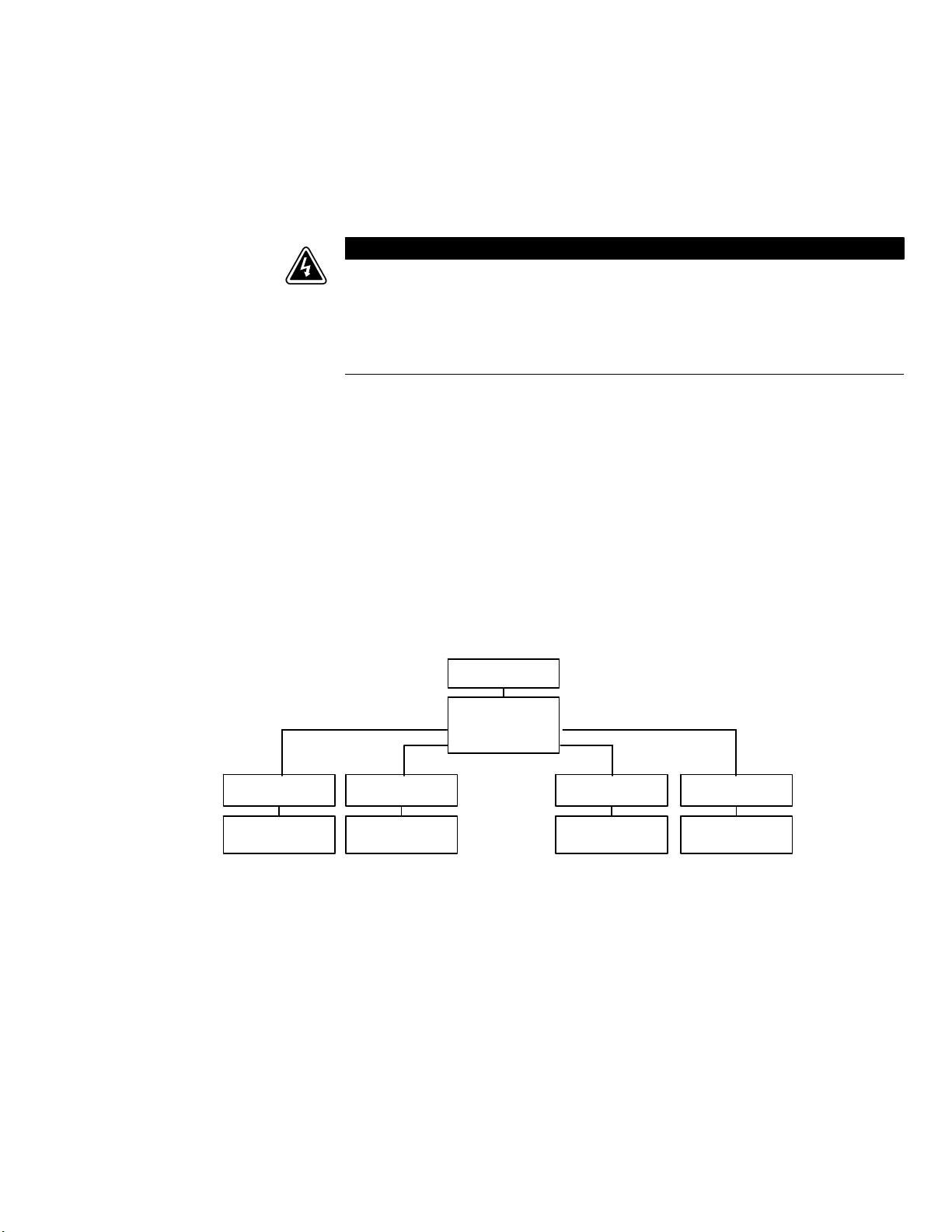
W A R N I N G
MASTER UPS
MASTER
INTERFACE
ENCLOSURE
FMSC #1 FMSC #4
NON-MASTER
UPS
Figure 3‐1. Fixed Master Sync Control with Master Interface Enclosure Functional Diagram
FMSC #2 FMSC #3
NON-MASTER
UPS
NON-MASTER
UPS
NON-MASTER
UPS
Eaton 9315/9390/9395 Fixed Master Sync Control Installation and Operation Manual S P-164000023 Rev 1 www.eaton.com/powerquality
3-1
 Loading...