

Eaton 9170+ ASY-0652, 9170+ ASY-0675, ASY-0652, ASY-0675 User Manual

Powerware Series
Eaton 9170+ Battery Charger Module
Models ASY-0652 and ASY-0675
User's Guide
®
Special Symbols
The following are examples of symbols used on the UPS or accessories to alert you to important
information:
RISK OF ELECTRIC SHOCK - Observe the warning associated with the risk of
electric shock symbol.
CAUTION: REFER TO OPERATOR'S MANUAL - Refer to your operator's manual for
additional information, such as important operating and maintenance
instructions.
This symbol indicates that you should not discard the UPS or the UPS batteries
in the trash. This product contains sealed, lead‐acid batteries and must be
disposed of properly. For more information, contact your local recycling/reuse or
hazardous waste center.
This symbol indicates that you should not discard waste electrical or electronic
equipment (WEEE) in the trash. For proper disposal, contact your local
recycling/reuse or hazardous waste center.
Eaton and Powerware are registered trademarks of Eaton Corporation or its subsidiaries and affiliates. All other
trademarks are property of their respective companies.
ECopyright 2002–2010 Eaton Corporation, Raleigh, NC, USA. All rights reserved. No part of this document may be
reproduced in any way without the express written approval of Eaton Corporation.

Eaton 9170+ Battery Charger Module User's Guide S 164201399 Rev E
www.eaton.com/powerquality
i
Table of Contents
1 Introduction 1. . . . . . . . . . . . . . . . . . . . . . . . . . . . . . . . . . . . . . . . . . . . . . . . . . . . . . . . .
Physical Features 2. . . . . . . . . . . . . . . . . . . . . . . . . . . . . . . . . . . . . . . . . . . . . . . . . . . . . . . . . . . . . . . . . . . . .
2 Installation 5. . . . . . . . . . . . . . . . . . . . . . . . . . . . . . . . . . . . . . . . . . . . . . . . . . . . . . . . . .
Cabinet Preparation 5. . . . . . . . . . . . . . . . . . . . . . . . . . . . . . . . . . . . . . . . . . . . . . . . . . . . . . . . . . . . . . . . . . .
DC Cabling Between Cabinets 6. . . . . . . . . . . . . . . . . . . . . . . . . . . . . . . . . . . . . . . . . . . . . . . . . . . . . . . . . . .
Setting DIP Switches 6. . . . . . . . . . . . . . . . . . . . . . . . . . . . . . . . . . . . . . . . . . . . . . . . . . . . . . . . . . . . . . . . . .
Output Current Limit 6. . . . . . . . . . . . . . . . . . . . . . . . . . . . . . . . . . . . . . . . . . . . . . . . . . . . . . . . . . . . . . . .
Periodic Float Charge 7. . . . . . . . . . . . . . . . . . . . . . . . . . . . . . . . . . . . . . . . . . . . . . . . . . . . . . . . . . . . . . .
Reserved Switch 7. . . . . . . . . . . . . . . . . . . . . . . . . . . . . . . . . . . . . . . . . . . . . . . . . . . . . . . . . . . . . . . . . .
Battery Charger Module Installation 8. . . . . . . . . . . . . . . . . . . . . . . . . . . . . . . . . . . . . . . . . . . . . . . . . . . . . . .
3 Operation 9. . . . . . . . . . . . . . . . . . . . . . . . . . . . . . . . . . . . . . . . . . . . . . . . . . . . . . . . . . .
UPS Cabinet Operation 9. . . . . . . . . . . . . . . . . . . . . . . . . . . . . . . . . . . . . . . . . . . . . . . . . . . . . . . . . . . . . . . . .
External Battery Cabinet Operation 9. . . . . . . . . . . . . . . . . . . . . . . . . . . . . . . . . . . . . . . . . . . . . . . . . . . . . . . .
Output Foldback 9. . . . . . . . . . . . . . . . . . . . . . . . . . . . . . . . . . . . . . . . . . . . . . . . . . . . . . . . . . . . . . . . . . . . .
4 Specifications 11. . . . . . . . . . . . . . . . . . . . . . . . . . . . . . . . . . . . . . . . . . . . . . . . . . . . . . .
5 Troubleshooting 21. . . . . . . . . . . . . . . . . . . . . . . . . . . . . . . . . . . . . . . . . . . . . . . . . . . . . .
Alarm Messages 21. . . . . . . . . . . . . . . . . . . . . . . . . . . . . . . . . . . . . . . . . . . . . . . . . . . . . . . . . . . . . . . . . . . . .
Audible Alarms and UPS Conditions 21. . . . . . . . . . . . . . . . . . . . . . . . . . . . . . . . . . . . . . . . . . . . . . . . . . . . . . .
Battery Charger Module Replacement 22. . . . . . . . . . . . . . . . . . . . . . . . . . . . . . . . . . . . . . . . . . . . . . . . . . . . . .
Service and Support 23. . . . . . . . . . . . . . . . . . . . . . . . . . . . . . . . . . . . . . . . . . . . . . . . . . . . . . . . . . . . . . . . . . .

TABLE OF CONTENTS
Eaton 9170+ Battery Charger Module User's Guide S 164201399 Rev E
www.eaton.com/powerquality
ii
Eaton 9170+ Battery Charger Module User's Guide S 164201399 Rev E
www.eaton.com/powerquality
1
Chapter 1 Introduction
The optional Battery Charger Module is designed to provide additional
current for faster recharging of uninterruptible power system (UPS)
battery modules in systems with many batteries.
NOTE To realize maximum module functionality, install Battery Charger Modules in the
UPS cabinet.
For systems with especially long runtime requirements, DIP switches on
the rear panel of the Battery Charger Module make it possible to install
the module in a specially designed external battery cabinet (ASY-0739).
The Battery Charger Module is capable of providing up to 20 amperes of
current for optimum charging, based upon the condition and number of
batteries in the system.
Examples of improved system recharge times are shown in Table 1.
Note that larger systems require at least one (or more) Battery Charger
Modules to be able to recharge the larger number of battery modules.
Table 1. Recharge Times Using Battery Charger Modules
Designed
Runtime
(Minutes)
Number of
Battery
Charger
Modules
6 kVA Capacity 12 kVA Capacity 18 kVA Capacity
Battery
Modules
Recharge
Time (Hours)
Battery
Modules
Recharge
Time (Hours)
Battery
Modules
Recharge
Time (Hours)
58
0
16
20
32
20
48
20
1 3 4 6
120 1 28 5 56 8 82 11
240
1
54
9
110
17
160
N/A
2 6 9 13
360
1
78
14
160
N/A
234
N/A
2 7 14 19
480
1
102
18
200
N/A
308
N/A
2 10 18 26
3 7 13 18
INTRODUCTION
Eaton 9170+ Battery Charger Module User's Guide S 164201399 Rev E
www.eaton.com/powerquality
2
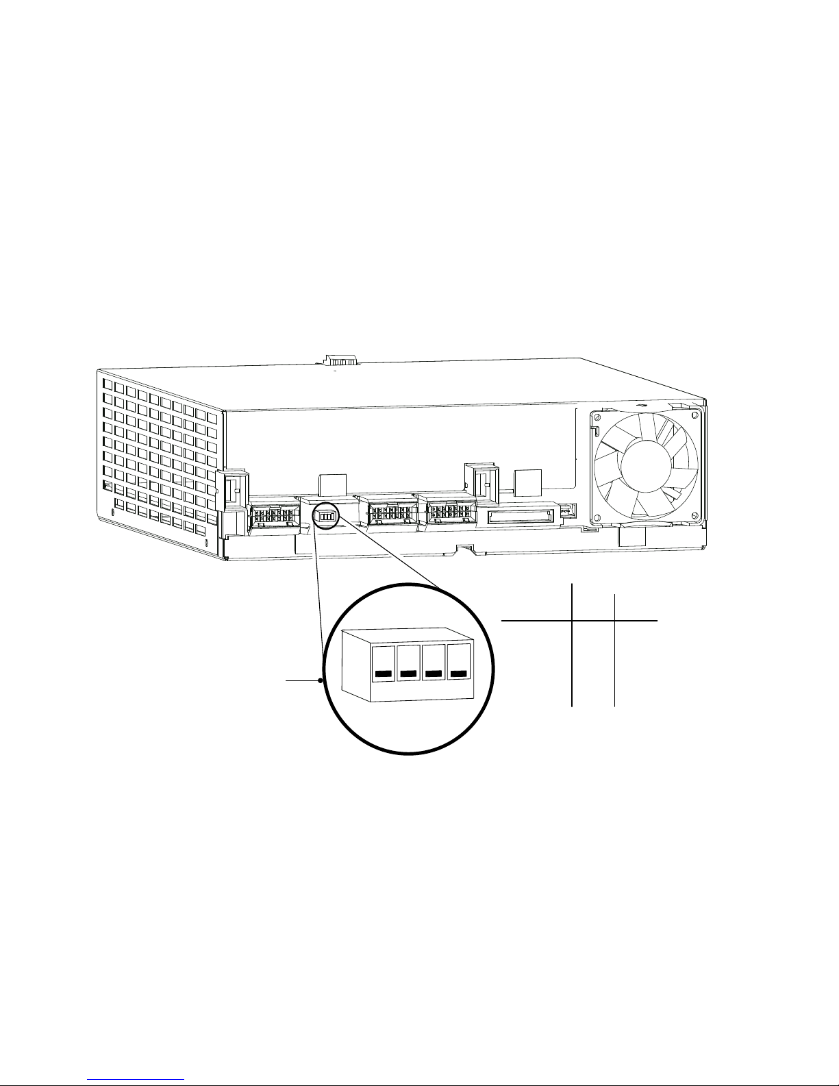
Physical Features
The Battery Charger Module is similar in appearance to a power module.
The two primary differences are the front label color (light-purple for the
ASY-0652 and orange for the ASY-0675) and the current-limit DIP switch
on the rear panel of the module as shown in Figure 1. See “Setting DIP
Switches” on page 6 for more information on DIP switch functions.
The module may be installed in either the UPS cabinet (6-, 9-, and 12-slot
sizes) or a special 12-slot external battery cabinet.
On
Off
On
DIP Switch Detail
* Factory default setting
1
2
3
4
Current
Limit
12
5A Off Off*
10A Off
Off15A On
On20A On
Figure 1. Battery Charger Module (Rear View)
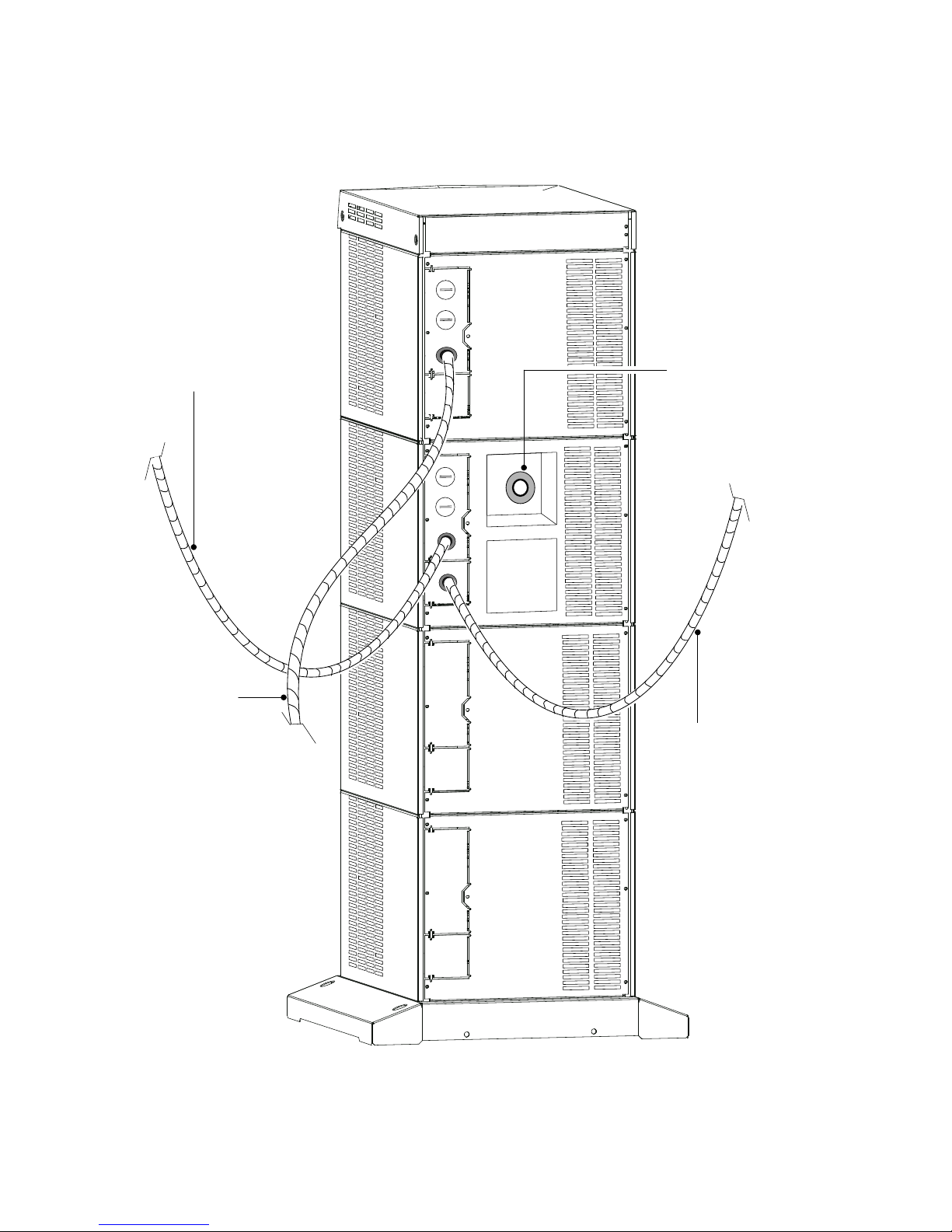
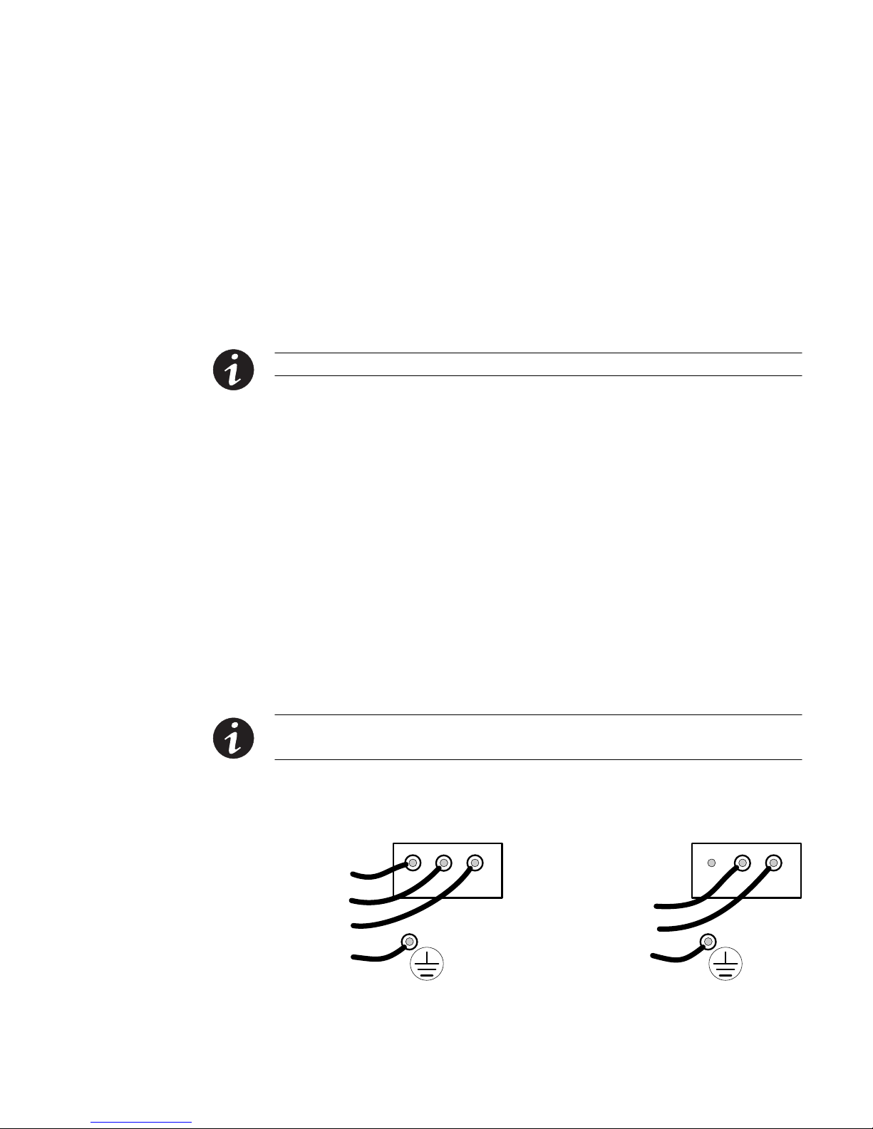
The external battery cabinet may have input power hardwired through
rigid or flexible conduit, as shown in Figure 2, or input power may be
supplied through a plug-terminated line cord (requires the purchase of a
line cord kit). Besides input power, the external battery cabinet has a
cable or conduit connection to the UPS cabinet. It may also have a cable
or conduit to additional external battery cabinets.
INTRODUCTION
Eaton 9170+ Battery Charger Module User's Guide S 164201399 Rev E
www.eaton.com/powerquality
3
To UPS or Previous External
Battery Cabinet
AC Line In
To Next External Battery Cabinet
DC Disconnect Switch
Button
Figure 2. External Battery Cabinet for Charger Modules

INTRODUCTION
Eaton 9170+ Battery Charger Module User's Guide S 164201399 Rev E
www.eaton.com/powerquality
4
Eaton 9170+ Battery Charger Module User's Guide S 164201399 Rev E
www.eaton.com/powerquality
5
Chapter 2 Installation
The Battery Charger Module can be plugged into any UPS cabinet slot
above the battery modules. Battery Charger Modules may be installed in
any of the top three slots of the ASY-0739 12-slot external battery
cabinet.
NOTE Do not block the cabinet's ventilation holes on the sides or the back.
Cabinet Preparation
Follow the procedures in the UPS user's guide for:
S Equipment clearances
S Installing the UPS cabinet and optional external battery cabinets
If additional external battery cabinets are to be used for Battery Charger
Modules, install input power wiring to each additional cabinet (see
Figure 3). Table 2 shows required wire sizes based upon the number of
Battery Charger Modules.
For each 12-slot external battery cabinet, stabilizer brackets must be
installed. If required, also install a floor anchor kit as described in the
UPS user's guide.
NOTE The ASY-0739 12-slot external battery cabinet must be wired for input power from the
utility AC power supply.
(b) Universal Power Modules
(2-wire plus ground input)
200, 208, 220, 230, and 240 Vac
(a) Split-Phase Power Modules
(3-wire plus ground input) (2 PEN)
100/200, 110/220, 120/208, 120/240, 127/220 Vac
321321
L2
L1
N
GND
L1
L2/N
GND
Figure 3. Input Power Wiring to ASY-0739 External Battery Cabinet
INSTALLATION
Eaton 9170+ Battery Charger Module User's Guide S 164201399 Rev E
www.eaton.com/powerquality
6
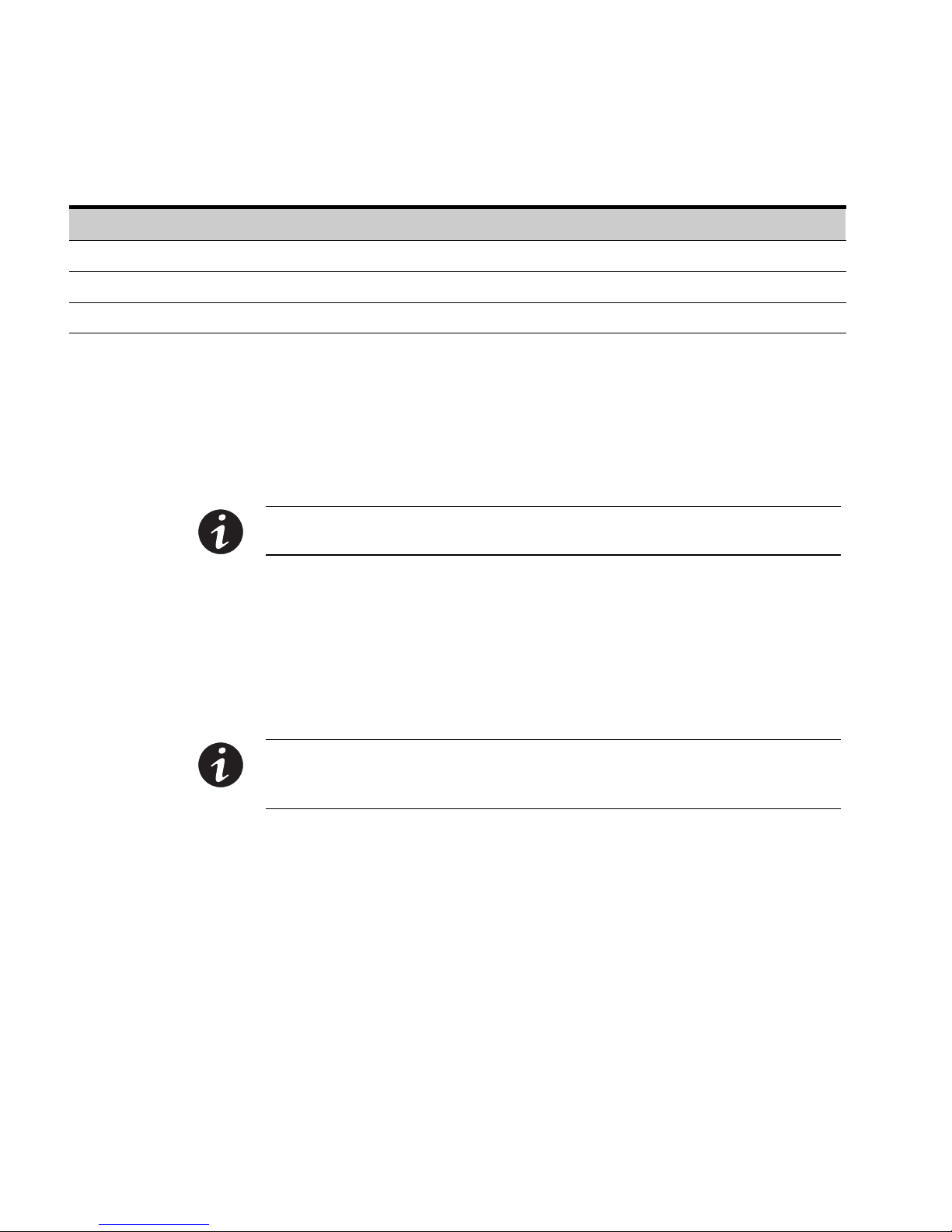
Table 2. Required Input Wiring for ASY-0739 External Battery Cabinet
Number of Charger Modules Input Circuit Breaker Rating 75°C Copper Wire Size Conductor Screw Torque
1 15A 14/12 AWG 2.3 Nm (20 lb in)
2 30A 10 AWG 2.3 Nm (20 lb in)
3 45A 8 AWG 2.8 Nm (25 lb in)
DC Cabling Between Cabinets
Refer to “Battery Cabinet Installation” in the UPS user's guide for the
procedure to connect the cable assembly between the external battery
cabinet and the UPS cabinet, or to additional external battery cabinets.
NOTE See Figure 2 on page 3 for the proper location of cabinet-to-cabinet wiring, which
must be in the second cabinet section.
Setting DIP Switches
The DIP switches on the rear panel of the Battery Charger Module are
functional only when the module is installed in an external battery
cabinet. The DIP switches control two functions: the output current
limit and a periodic float charging to equalize all battery capacities.
NOTE Set the DIP switches ONLY if the Battery Charger Module is placed in the ASY-0739
12-slot external battery cabinet. When the module is placed in the UPS cabinet, do not set
the DIP switches.
Output Current Limit
The Battery Charger Module is capable of producing up to 5A, 10A, 15A,
or 20A when installed in an external battery cabinet. Discharged
batteries must be recharged at an optimum rate, neither too quickly nor
too slowly. For optimum charging of batteries, you must set DIP
switches 1 and 2.
Follow the guidelines in Table 3 to determine the proper output current
setting and set DIP switches 1 and 2 accordingly (see Figure 4).
 Loading...