

Eaton 9395 UPS, Plus 1 UPS, 825 UPS, 550 UPS, 9395 Installation And Operation Manual
...
Powerware Series
Eaton 9395 UPS, Plus 1 UPS, and 825/550 UPS
®
450–825 kVA
Installation and Operation Manual
For use with Two UPM (450–550 kVA), Three UPM (650–825 kVA), and
Plus 1 (650–825 kVA) UPS Models


Powerware Series
Eaton 9395 UPS, Plus 1 UPS, and 825/550 UPS
®
450–825 kVA
Installation and Operation Manual
For use with Two UPM (450–550 kVA), Three UPM (650–825 kVA), and
Plus 1 (650–825 kVA) UPS Models

IMPORTANT SAFETY INSTRUCTIONS
SAVE THESE INSTRUCTIONS
This manual contains important instructions that you should follow during installation and maintenance of the UPS and batteries. Please
read all instructions before operating the equipment and save this manual for future reference.
CONSIGNES DE SÉCURITÉ IMPORTANTES
CONSERVER CES INSTRUCTIONS
Ce manuel comporte des instructions importantes que vous êtes invité à suivre lors de toute procédure d'installation et de maintenance
des batteries et de l'onduleur. Veuillez consulter entièrement ces instructions avant de faire fonctionner l'équipement et conserver ce
manuel afin de pouvoir vous y reporter ultérieurement.
W A R N I N G
This is a product for restricted sales distribution to informed partners (EN/IEC 62040-2). Installation restrictions or additional measures
may be needed to prevent electromagnetic disturbances.
Eaton, Powerware, LanSafe, Power Xpert, Powerware Hot Sync, and X-Slot are registered trademarks and ConnectUPS is a
trademark of Eaton Corporation or its subsidiaries and affiliates. IBM and AS/400 are registered trademarks of International
Business Machines Corporation. Modbus is a registered trademark of Schneider Automation. National Electrical Code and NEC
are registered trademarks of National Fire Protection Association, Inc. All other trademarks are property of their respective
companies.
ECopyright 2008–2010 Eaton Corporation, Raleigh, NC, USA. All rights reserved. No part of this document may be reproduced
in any way without the express written approval of Eaton Corporation.

Table of Contents
1 Introduction 1-1. . . . . . . . . . . . . . . . . . . . . . . . . . . . . . . . . . . . . . . . . . . . . . . . . . . . . . . . . . . . . . . . . . . . . . . . . . .
1.1 UPS Standard Features 1-4. . . . . . . . . . . . . . . . . . . . . . . . . . . . . . . . . . . . . . . . . . . . . . . . . . . . . . . . . . . . . . . . . . . . . . . . . . . . . . . . .
1.1.1 Installation Features 1-4. . . . . . . . . . . . . . . . . . . . . . . . . . . . . . . . . . . . . . . . . . . . . . . . . . . . . . . . . . . . . . . . . . . . . . . . . . . . . . .
1.1.2 Control Panel 1-4. . . . . . . . . . . . . . . . . . . . . . . . . . . . . . . . . . . . . . . . . . . . . . . . . . . . . . . . . . . . . . . . . . . . . . . . . . . . . . . . . . . .
1.1.3 Customer Interface 1-4. . . . . . . . . . . . . . . . . . . . . . . . . . . . . . . . . . . . . . . . . . . . . . . . . . . . . . . . . . . . . . . . . . . . . . . . . . . . . . . .
1.1.4 Advanced Battery Management 1-4. . . . . . . . . . . . . . . . . . . . . . . . . . . . . . . . . . . . . . . . . . . . . . . . . . . . . . . . . . . . . . . . . . . . . . .
1.1.5 Power Management Software 1-4. . . . . . . . . . . . . . . . . . . . . . . . . . . . . . . . . . . . . . . . . . . . . . . . . . . . . . . . . . . . . . . . . . . . . . . .
1.2 Options and Accessories 1-5. . . . . . . . . . . . . . . . . . . . . . . . . . . . . . . . . . . . . . . . . . . . . . . . . . . . . . . . . . . . . . . . . . . . . . . . . . . . . . . .
1.2.1 Field Installed UPM 1-5. . . . . . . . . . . . . . . . . . . . . . . . . . . . . . . . . . . . . . . . . . . . . . . . . . . . . . . . . . . . . . . . . . . . . . . . . . . . . . .
1.2.2 Sync Control 1-5. . . . . . . . . . . . . . . . . . . . . . . . . . . . . . . . . . . . . . . . . . . . . . . . . . . . . . . . . . . . . . . . . . . . . . . . . . . . . . . . . . . .
1.2.3 Single-Feed Kit 1-5. . . . . . . . . . . . . . . . . . . . . . . . . . . . . . . . . . . . . . . . . . . . . . . . . . . . . . . . . . . . . . . . . . . . . . . . . . . . . . . . . .
1.2.4 Separate Rectifier Input 1-5. . . . . . . . . . . . . . . . . . . . . . . . . . . . . . . . . . . . . . . . . . . . . . . . . . . . . . . . . . . . . . . . . . . . . . . . . . . .
1.2.5 Distributed Bypass System 1-5. . . . . . . . . . . . . . . . . . . . . . . . . . . . . . . . . . . . . . . . . . . . . . . . . . . . . . . . . . . . . . . . . . . . . . . . . .
1.2.6 Input Output Module Configuration 1-6. . . . . . . . . . . . . . . . . . . . . . . . . . . . . . . . . . . . . . . . . . . . . . . . . . . . . . . . . . . . . . . . . . . .
1.2.7 Continuous Static Switch 1-6. . . . . . . . . . . . . . . . . . . . . . . . . . . . . . . . . . . . . . . . . . . . . . . . . . . . . . . . . . . . . . . . . . . . . . . . . . .
1.2.8 Inherent Redundancy 1-6. . . . . . . . . . . . . . . . . . . . . . . . . . . . . . . . . . . . . . . . . . . . . . . . . . . . . . . . . . . . . . . . . . . . . . . . . . . . . .
1.2.9 Energy Saver System and High Alert Modes 1-6. . . . . . . . . . . . . . . . . . . . . . . . . . . . . . . . . . . . . . . . . . . . . . . . . . . . . . . . . . . . . .
1.2.10 Variable Module Management System and High Alert Modes 1-7. . . . . . . . . . . . . . . . . . . . . . . . . . . . . . . . . . . . . . . . . . . . . . . . . .
1.2.11 Monitoring and Communication 1-7. . . . . . . . . . . . . . . . . . . . . . . . . . . . . . . . . . . . . . . . . . . . . . . . . . . . . . . . . . . . . . . . . . . . . . .
1.3 Battery System 1-8. . . . . . . . . . . . . . . . . . . . . . . . . . . . . . . . . . . . . . . . . . . . . . . . . . . . . . . . . . . . . . . . . . . . . . . . . . . . . . . . . . . . . . .
1.4 Basic System Configurations 1-8. . . . . . . . . . . . . . . . . . . . . . . . . . . . . . . . . . . . . . . . . . . . . . . . . . . . . . . . . . . . . . . . . . . . . . . . . . . . .
1.5 Using This Manual 1-9. . . . . . . . . . . . . . . . . . . . . . . . . . . . . . . . . . . . . . . . . . . . . . . . . . . . . . . . . . . . . . . . . . . . . . . . . . . . . . . . . . . .
1.6 Conventions Used in This Manual 1-9. . . . . . . . . . . . . . . . . . . . . . . . . . . . . . . . . . . . . . . . . . . . . . . . . . . . . . . . . . . . . . . . . . . . . . . . . .
1.7 Symbols, Controls, and Indicators 1-10. . . . . . . . . . . . . . . . . . . . . . . . . . . . . . . . . . . . . . . . . . . . . . . . . . . . . . . . . . . . . . . . . . . . . . . . . .
1.8 For More Information 1-10. . . . . . . . . . . . . . . . . . . . . . . . . . . . . . . . . . . . . . . . . . . . . . . . . . . . . . . . . . . . . . . . . . . . . . . . . . . . . . . . . . .
1.9 Getting Help 1-11. . . . . . . . . . . . . . . . . . . . . . . . . . . . . . . . . . . . . . . . . . . . . . . . . . . . . . . . . . . . . . . . . . . . . . . . . . . . . . . . . . . . . . . . .
2 Safety Warnings 2-1. . . . . . . . . . . . . . . . . . . . . . . . . . . . . . . . . . . . . . . . . . . . . . . . . . . . . . . . . . . . . . . . . . . . . . .
Section I – Installation
3 UPS Installation Plan and Unpacking 3-1. . . . . . . . . . . . . . . . . . . . . . . . . . . . . . . . . . . . . . . . . . . . . . . . . . . . . . .
3.1 Creating an Installation Plan 3-1. . . . . . . . . . . . . . . . . . . . . . . . . . . . . . . . . . . . . . . . . . . . . . . . . . . . . . . . . . . . . . . . . . . . . . . . . . . . . .
3.2 Preparing the Site 3-1. . . . . . . . . . . . . . . . . . . . . . . . . . . . . . . . . . . . . . . . . . . . . . . . . . . . . . . . . . . . . . . . . . . . . . . . . . . . . . . . . . . . .
3.2.1 Environmental and Installation Considerations 3-1. . . . . . . . . . . . . . . . . . . . . . . . . . . . . . . . . . . . . . . . . . . . . . . . . . . . . . . . . . . . .
3.2.2 UPS System Power Wiring Preparation 3-11. . . . . . . . . . . . . . . . . . . . . . . . . . . . . . . . . . . . . . . . . . . . . . . . . . . . . . . . . . . . . . . . . .
3.2.3 UPS System Interface Wiring Preparation 3-27. . . . . . . . . . . . . . . . . . . . . . . . . . . . . . . . . . . . . . . . . . . . . . . . . . . . . . . . . . . . . . . .
3.2.4 Distributed Bypass Power Wiring Preparation 3-28. . . . . . . . . . . . . . . . . . . . . . . . . . . . . . . . . . . . . . . . . . . . . . . . . . . . . . . . . . . . .
3.3 Inspecting and Unpacking the UPS Cabinets 3-29. . . . . . . . . . . . . . . . . . . . . . . . . . . . . . . . . . . . . . . . . . . . . . . . . . . . . . . . . . . . . . . . . . .
4 UPS System Installation 4-1. . . . . . . . . . . . . . . . . . . . . . . . . . . . . . . . . . . . . . . . . . . . . . . . . . . . . . . . . . . . . . . . .
4.1 Preliminary Installation Information 4-1. . . . . . . . . . . . . . . . . . . . . . . . . . . . . . . . . . . . . . . . . . . . . . . . . . . . . . . . . . . . . . . . . . . . . . . . .
4.2 Unloading the UPS Sections from the Pallet 4-1. . . . . . . . . . . . . . . . . . . . . . . . . . . . . . . . . . . . . . . . . . . . . . . . . . . . . . . . . . . . . . . . . . .
4.3 Mechanically Joining the Sections 4-7. . . . . . . . . . . . . . . . . . . . . . . . . . . . . . . . . . . . . . . . . . . . . . . . . . . . . . . . . . . . . . . . . . . . . . . . .
4.4 Electrically Connecting the Sections 4-10. . . . . . . . . . . . . . . . . . . . . . . . . . . . . . . . . . . . . . . . . . . . . . . . . . . . . . . . . . . . . . . . . . . . . . . .
4.5 Field Installed UPM Installation 4-23. . . . . . . . . . . . . . . . . . . . . . . . . . . . . . . . . . . . . . . . . . . . . . . . . . . . . . . . . . . . . . . . . . . . . . . . . . .
4.6 Battery System Installation 4-23. . . . . . . . . . . . . . . . . . . . . . . . . . . . . . . . . . . . . . . . . . . . . . . . . . . . . . . . . . . . . . . . . . . . . . . . . . . . . . .
Eaton 9395 UPS (450–825 kVA) Installation and Operation Manual S 164201725 Rev 4 www.eaton.com/powerquality
i

TABLE OF CONTENTS
4.7 Distributed Bypass Tie Cabinet Installation 4-23. . . . . . . . . . . . . . . . . . . . . . . . . . . . . . . . . . . . . . . . . . . . . . . . . . . . . . . . . . . . . . . . . . .
4.8 Installing UPS External and Battery Power Wiring 4-23. . . . . . . . . . . . . . . . . . . . . . . . . . . . . . . . . . . . . . . . . . . . . . . . . . . . . . . . . . . . . . .
4.8.1 2‐Hole Barrel Lug Terminations to Bus Bar Installation 4-24. . . . . . . . . . . . . . . . . . . . . . . . . . . . . . . . . . . . . . . . . . . . . . . . . . . . . . .
4.8.2 External Power Wiring Installation 4-25. . . . . . . . . . . . . . . . . . . . . . . . . . . . . . . . . . . . . . . . . . . . . . . . . . . . . . . . . . . . . . . . . . . . .
4.8.3 Battery Power Wiring 4-37. . . . . . . . . . . . . . . . . . . . . . . . . . . . . . . . . . . . . . . . . . . . . . . . . . . . . . . . . . . . . . . . . . . . . . . . . . . . . .
4.9 Installing Interface Connections 4-40. . . . . . . . . . . . . . . . . . . . . . . . . . . . . . . . . . . . . . . . . . . . . . . . . . . . . . . . . . . . . . . . . . . . . . . . . . .
4.9.1 TB1, TB2, and TB3 Connections (Other than TB1 Battery Interface Connections) 4-40. . . . . . . . . . . . . . . . . . . . . . . . . . . . . . . . . . . . .
4.9.2 TB1 Battery Interface Connections 4-45. . . . . . . . . . . . . . . . . . . . . . . . . . . . . . . . . . . . . . . . . . . . . . . . . . . . . . . . . . . . . . . . . . . . .
4.9.3 X-Slot Connections 4-47. . . . . . . . . . . . . . . . . . . . . . . . . . . . . . . . . . . . . . . . . . . . . . . . . . . . . . . . . . . . . . . . . . . . . . . . . . . . . . . .
4.10 Installing a REPO Switch 4-48. . . . . . . . . . . . . . . . . . . . . . . . . . . . . . . . . . . . . . . . . . . . . . . . . . . . . . . . . . . . . . . . . . . . . . . . . . . . . . . .
4.11 Installing Options, Accessories, and Distributed Bypass Control Wiring 4-51. . . . . . . . . . . . . . . . . . . . . . . . . . . . . . . . . . . . . . . . . . . . . . . .
4.12 Initial Startup 4-51. . . . . . . . . . . . . . . . . . . . . . . . . . . . . . . . . . . . . . . . . . . . . . . . . . . . . . . . . . . . . . . . . . . . . . . . . . . . . . . . . . . . . . . .
4.13 Completing the Installation Checklist 4-51. . . . . . . . . . . . . . . . . . . . . . . . . . . . . . . . . . . . . . . . . . . . . . . . . . . . . . . . . . . . . . . . . . . . . . . .
5 Installing Options and Accessories 5-1. . . . . . . . . . . . . . . . . . . . . . . . . . . . . . . . . . . . . . . . . . . . . . . . . . . . . . . .
5.1 Installing an Optional Powerware Hot Sync CAN Bridge Card 5-1. . . . . . . . . . . . . . . . . . . . . . . . . . . . . . . . . . . . . . . . . . . . . . . . . . . . . . .
5.2 Installing Distributed Bypass Control Wiring 5-4. . . . . . . . . . . . . . . . . . . . . . . . . . . . . . . . . . . . . . . . . . . . . . . . . . . . . . . . . . . . . . . . . . .
5.3 Installing an Optional Remote Monitor Panel II 5-9. . . . . . . . . . . . . . . . . . . . . . . . . . . . . . . . . . . . . . . . . . . . . . . . . . . . . . . . . . . . . . . . .
5.4 Installing an Optional Relay Interface Module II 5-11. . . . . . . . . . . . . . . . . . . . . . . . . . . . . . . . . . . . . . . . . . . . . . . . . . . . . . . . . . . . . . . .
5.5 Installing an Optional Supervisory Contact Module II 5-13. . . . . . . . . . . . . . . . . . . . . . . . . . . . . . . . . . . . . . . . . . . . . . . . . . . . . . . . . . . . .
5.6 Accessory Mounting Dimensions 5-15. . . . . . . . . . . . . . . . . . . . . . . . . . . . . . . . . . . . . . . . . . . . . . . . . . . . . . . . . . . . . . . . . . . . . . . . . . .
Section II – Operation
6 Understanding UPS Operation 6-1. . . . . . . . . . . . . . . . . . . . . . . . . . . . . . . . . . . . . . . . . . . . . . . . . . . . . . . . . . . . .
6.1 UPS System Overview 6-1. . . . . . . . . . . . . . . . . . . . . . . . . . . . . . . . . . . . . . . . . . . . . . . . . . . . . . . . . . . . . . . . . . . . . . . . . . . . . . . . . .
6.2 Single UPS 6-2. . . . . . . . . . . . . . . . . . . . . . . . . . . . . . . . . . . . . . . . . . . . . . . . . . . . . . . . . . . . . . . . . . . . . . . . . . . . . . . . . . . . . . . . . .
6.2.1 Modes 6-2. . . . . . . . . . . . . . . . . . . . . . . . . . . . . . . . . . . . . . . . . . . . . . . . . . . . . . . . . . . . . . . . . . . . . . . . . . . . . . . . . . . . . . . .
6.2.2 Online Mode 6-3. . . . . . . . . . . . . . . . . . . . . . . . . . . . . . . . . . . . . . . . . . . . . . . . . . . . . . . . . . . . . . . . . . . . . . . . . . . . . . . . . . . .
6.2.3 Energy Saver System Mode 6-4. . . . . . . . . . . . . . . . . . . . . . . . . . . . . . . . . . . . . . . . . . . . . . . . . . . . . . . . . . . . . . . . . . . . . . . . . .
6.2.4 Variable Module Management System 6-4. . . . . . . . . . . . . . . . . . . . . . . . . . . . . . . . . . . . . . . . . . . . . . . . . . . . . . . . . . . . . . . . . .
6.2.5 Bypass Mode 6-5. . . . . . . . . . . . . . . . . . . . . . . . . . . . . . . . . . . . . . . . . . . . . . . . . . . . . . . . . . . . . . . . . . . . . . . . . . . . . . . . . . . .
6.2.6 Battery Mode 6-6. . . . . . . . . . . . . . . . . . . . . . . . . . . . . . . . . . . . . . . . . . . . . . . . . . . . . . . . . . . . . . . . . . . . . . . . . . . . . . . . . . . .
6.3 Single UPS Unit System Oneline Configurations 6-8. . . . . . . . . . . . . . . . . . . . . . . . . . . . . . . . . . . . . . . . . . . . . . . . . . . . . . . . . . . . . . . .
6.4 Multiple UPS Distributed Bypass System 6-35. . . . . . . . . . . . . . . . . . . . . . . . . . . . . . . . . . . . . . . . . . . . . . . . . . . . . . . . . . . . . . . . . . . . .
6.4.1 Multiple UPS Parallel System Modes 6-35. . . . . . . . . . . . . . . . . . . . . . . . . . . . . . . . . . . . . . . . . . . . . . . . . . . . . . . . . . . . . . . . . . .
6.4.2 Online Mode – Distributed Bypass 6-36. . . . . . . . . . . . . . . . . . . . . . . . . . . . . . . . . . . . . . . . . . . . . . . . . . . . . . . . . . . . . . . . . . . . .
6.4.3 Bypass Mode – Distributed Bypass 6-37. . . . . . . . . . . . . . . . . . . . . . . . . . . . . . . . . . . . . . . . . . . . . . . . . . . . . . . . . . . . . . . . . . . .
6.4.4 Battery Mode – Distributed Bypass 6-39. . . . . . . . . . . . . . . . . . . . . . . . . . . . . . . . . . . . . . . . . . . . . . . . . . . . . . . . . . . . . . . . . . . .
6.5 Multiple UPS Distributed Bypass System Oneline Configurations 6-40. . . . . . . . . . . . . . . . . . . . . . . . . . . . . . . . . . . . . . . . . . . . . . . . . . . .
7 UPS Operating Instructions 7-1. . . . . . . . . . . . . . . . . . . . . . . . . . . . . . . . . . . . . . . . . . . . . . . . . . . . . . . . . . . . . . .
7.1 UPS Controls and Indicators 7-1. . . . . . . . . . . . . . . . . . . . . . . . . . . . . . . . . . . . . . . . . . . . . . . . . . . . . . . . . . . . . . . . . . . . . . . . . . . . . .
7.1.1 Control Panel 7-2. . . . . . . . . . . . . . . . . . . . . . . . . . . . . . . . . . . . . . . . . . . . . . . . . . . . . . . . . . . . . . . . . . . . . . . . . . . . . . . . . . . .
7.1.2 Circuit Breakers 7-2. . . . . . . . . . . . . . . . . . . . . . . . . . . . . . . . . . . . . . . . . . . . . . . . . . . . . . . . . . . . . . . . . . . . . . . . . . . . . . . . . .
ii
Eaton 9395 UPS (450–825 kVA) Installation and Operation Manual S 164201725 Rev 4 www.eaton.com/powerquality

TABLE OF CONTENTS
7.2 Using the Control Panel 7-3. . . . . . . . . . . . . . . . . . . . . . . . . . . . . . . . . . . . . . . . . . . . . . . . . . . . . . . . . . . . . . . . . . . . . . . . . . . . . . . . .
7.2.1 Status Indicators 7-4. . . . . . . . . . . . . . . . . . . . . . . . . . . . . . . . . . . . . . . . . . . . . . . . . . . . . . . . . . . . . . . . . . . . . . . . . . . . . . . . .
7.2.2 System Events 7-4. . . . . . . . . . . . . . . . . . . . . . . . . . . . . . . . . . . . . . . . . . . . . . . . . . . . . . . . . . . . . . . . . . . . . . . . . . . . . . . . . . .
7.2.3 Using the LCD and Pushbuttons 7-5. . . . . . . . . . . . . . . . . . . . . . . . . . . . . . . . . . . . . . . . . . . . . . . . . . . . . . . . . . . . . . . . . . . . . . .
7.2.4 Using the Menu 7-6. . . . . . . . . . . . . . . . . . . . . . . . . . . . . . . . . . . . . . . . . . . . . . . . . . . . . . . . . . . . . . . . . . . . . . . . . . . . . . . . . .
7.2.5 Mimic Screen 7-6. . . . . . . . . . . . . . . . . . . . . . . . . . . . . . . . . . . . . . . . . . . . . . . . . . . . . . . . . . . . . . . . . . . . . . . . . . . . . . . . . . .
7.2.6 Display Menu Operation 7-7. . . . . . . . . . . . . . . . . . . . . . . . . . . . . . . . . . . . . . . . . . . . . . . . . . . . . . . . . . . . . . . . . . . . . . . . . . . .
7.2.7 Load Off Screen 7-10. . . . . . . . . . . . . . . . . . . . . . . . . . . . . . . . . . . . . . . . . . . . . . . . . . . . . . . . . . . . . . . . . . . . . . . . . . . . . . . . . .
7.2.8 System Status Screen and Controls 7-11. . . . . . . . . . . . . . . . . . . . . . . . . . . . . . . . . . . . . . . . . . . . . . . . . . . . . . . . . . . . . . . . . . . .
7.3 Single UPS Operation 7-13. . . . . . . . . . . . . . . . . . . . . . . . . . . . . . . . . . . . . . . . . . . . . . . . . . . . . . . . . . . . . . . . . . . . . . . . . . . . . . . . . .
7.3.1 Starting the UPS in Online Mode 7-13. . . . . . . . . . . . . . . . . . . . . . . . . . . . . . . . . . . . . . . . . . . . . . . . . . . . . . . . . . . . . . . . . . . . . .
7.3.2 Enable Energy Saver SystemMode from the UPS Command Menu 7-14. . . . . . . . . . . . . . . . . . . . . . . . . . . . . . . . . . . . . . . . . . . . . . .
7.3.3 Disable Energy Saver System Mode from the UPS Command Menu 7-15. . . . . . . . . . . . . . . . . . . . . . . . . . . . . . . . . . . . . . . . . . . . . .
7.3.4 Start Energy Saver System High Alert Mode from the UPS Command Menu 7-15. . . . . . . . . . . . . . . . . . . . . . . . . . . . . . . . . . . . . . . .
7.3.5 Enable Variable Module Management System Mode from the UPS Command Menu 7-16. . . . . . . . . . . . . . . . . . . . . . . . . . . . . . . . . .
7.3.6 Disable Variable Module Management System Mode from the UPS Command Menu 7-16. . . . . . . . . . . . . . . . . . . . . . . . . . . . . . . . .
7.3.7 Start Variable Module Management System High Alert Mode from the UPS Command Menu 7-17. . . . . . . . . . . . . . . . . . . . . . . . . . . .
7.3.8 Starting the UPS in Bypass Mode 7-17. . . . . . . . . . . . . . . . . . . . . . . . . . . . . . . . . . . . . . . . . . . . . . . . . . . . . . . . . . . . . . . . . . . . . .
7.3.9 Enable Energy Saver SystemMode from the Bypass Command Menu 7-18. . . . . . . . . . . . . . . . . . . . . . . . . . . . . . . . . . . . . . . . . . . . .
7.3.10 Disable Energy Saver System Mode from the Bypass Command Menu 7-19. . . . . . . . . . . . . . . . . . . . . . . . . . . . . . . . . . . . . . . . . . . .
7.3.11 Start Energy Saver System High Alert Mode from the Bypass Command Menu 7-19. . . . . . . . . . . . . . . . . . . . . . . . . . . . . . . . . . . . . .
7.3.12 Enable Variable Module Management System Mode from the Bypass Command Menu 7-20. . . . . . . . . . . . . . . . . . . . . . . . . . . . . . . .
7.3.13 Disable Variable Module Management System Mode from the Bypass Command Menu 7-20. . . . . . . . . . . . . . . . . . . . . . . . . . . . . . .
7.3.14 Start Variable Module Management System High Alert Mode from the Bypass Command Menu 7-21. . . . . . . . . . . . . . . . . . . . . . . . .
7.3.15 Starting the UPMs 7-21. . . . . . . . . . . . . . . . . . . . . . . . . . . . . . . . . . . . . . . . . . . . . . . . . . . . . . . . . . . . . . . . . . . . . . . . . . . . . . . .
7.3.16 Starting a Single UPM 7-23. . . . . . . . . . . . . . . . . . . . . . . . . . . . . . . . . . . . . . . . . . . . . . . . . . . . . . . . . . . . . . . . . . . . . . . . . . . . .
7.3.17 Transfer from Online to Bypass Mode 7-24. . . . . . . . . . . . . . . . . . . . . . . . . . . . . . . . . . . . . . . . . . . . . . . . . . . . . . . . . . . . . . . . . . .
7.3.18 Transfer from Bypass to Online Mode 7-24. . . . . . . . . . . . . . . . . . . . . . . . . . . . . . . . . . . . . . . . . . . . . . . . . . . . . . . . . . . . . . . . . . .
7.3.19 Transfer from Online to Bypass Mode and Shut Down UPMs 7-25. . . . . . . . . . . . . . . . . . . . . . . . . . . . . . . . . . . . . . . . . . . . . . . . . . .
7.3.20 Single UPM Shutdown 7-26. . . . . . . . . . . . . . . . . . . . . . . . . . . . . . . . . . . . . . . . . . . . . . . . . . . . . . . . . . . . . . . . . . . . . . . . . . . . .
7.3.21 Single UPM Restart 7-26. . . . . . . . . . . . . . . . . . . . . . . . . . . . . . . . . . . . . . . . . . . . . . . . . . . . . . . . . . . . . . . . . . . . . . . . . . . . . . .
7.3.22 UPS and Critical Load Shutdown 7-27. . . . . . . . . . . . . . . . . . . . . . . . . . . . . . . . . . . . . . . . . . . . . . . . . . . . . . . . . . . . . . . .
. . . . . .
7.3.23 Charger Control 7-27. . . . . . . . . . . . . . . . . . . . . . . . . . . . . . . . . . . . . . . . . . . . . . . . . . . . . . . . . . . . . . . . . . . . . . . . . . . . . . . . . .
7.3.24 Using the UPS LOAD OFF Pushbutton or Command 7-28. . . . . . . . . . . . . . . . . . . . . . . . . . . . . . . . . . . . . . . . . . . . . . . . . . . . . . . . . .
7.3.25 Using the Remote Emergency Power-off Switch 7-29. . . . . . . . . . . . . . . . . . . . . . . . . . . . . . . . . . . . . . . . . . . . . . . . . . . . . . . . . . . .
7.4 Multiple UPS Distributed Bypass Operation 7-31. . . . . . . . . . . . . . . . . . . . . . . . . . . . . . . . . . . . . . . . . . . . . . . . . . . . . . . . . . . . . . . . . . .
7.4.1 Starting the Distributed Bypass System in Online Mode 7-31. . . . . . . . . . . . . . . . . . . . . . . . . . . . . . . . . . . . . . . . . . . . . . . . . . . . . .
7.4.2 Enable Energy Saver SystemMode from the UPS Command Menu 7-32. . . . . . . . . . . . . . . . . . . . . . . . . . . . . . . . . . . . . . . . . . . . . . .
7.4.3 Disable Energy Saver System Mode from the UPS Command Menu 7-33. . . . . . . . . . . . . . . . . . . . . . . . . . . . . . . . . . . . . . . . . . . . . .
7.4.4 Start Energy Saver System High Alert Mode from the UPS Command Menu 7-33. . . . . . . . . . . . . . . . . . . . . . . . . . . . . . . . . . . . . . . .
7.4.5 Enable Variable Module Management System Mode from the UPS Command Menu 7-34. . . . . . . . . . . . . . . . . . . . . . . . . . . . . . . . . .
7.4.6 Disable Variable Module Management System Mode from the UPS Command Menu 7-34. . . . . . . . . . . . . . . . . . . . . . . . . . . . . . . . .
7.4.7 Start Variable Module Management System High Alert Mode from the UPS Command Menu 7-35. . . . . . . . . . . . . . . . . . . . . . . . . . . .
7.4.8 Starting the Distributed Bypass System in Bypass Mode 7-35. . . . . . . . . . . . . . . . . . . . . . . . . . . . . . . . . . . . . . . . . . . . . . . . . . . . .
7.4.9 Enable Energy Saver SystemMode from the Bypass Command Menu 7-36. . . . . . . . . . . . . . . . . . . . . . . . . . . . . . . . . . . . . . . . . . . . .
7.4.10 Disable Energy Saver System Mode from the Bypass Command Menu 7-37. . . . . . . . . . . . . . . . . . . . . . . . . . . . . . . . . . . . . . . . . . . .
7.4.11 Start Energy Saver System High Alert Mode from the Bypass Command Menu 7-37. . . . . . . . . . . . . . . . . . . . . . . . . . . . . . . . . . . . . .
7.4.12 Enable Variable Module Management System Mode from the Bypass Command Menu 7-38. . . . . . . . . . . . . . . . . . . . . . . . . . . . . . . .
7.4.13 Disable Variable Module Management System Mode from the Bypass Command Menu 7-38. . . . . . . . . . . . . . . . . . . . . . . . . . . . . . .
7.4.14 Start Variable Module Management System High Alert Mode from the Bypass Command Menu 7-39. . . . . . . . . . . . . . . . . . . . . . . . .
7.4.15 Starting the UPS UPMs 7-39. . . . . . . . . . . . . . . . . . . . . . . . . . . . . . . . . . . . . . . . . . . . . . . . . . . . . . . . . . . . . . . . . . . . . . . . . . . . .
Eaton 9395 UPS (450–825 kVA) Installation and Operation Manual S 164201725 Rev 4 www.eaton.com/powerquality
iii

TABLE OF CONTENTS
7.4.16 Starting a Single UPM 7-41. . . . . . . . . . . . . . . . . . . . . . . . . . . . . . . . . . . . . . . . . . . . . . . . . . . . . . . . . . . . . . . . . . . . . . . . . . . . .
7.4.17 Transfer from Online to Bypass Mode 7-42. . . . . . . . . . . . . . . . . . . . . . . . . . . . . . . . . . . . . . . . . . . . . . . . . . . . . . . . . . . . . . . . . . .
7.4.18 Transfer from Bypass to Online Mode 7-42. . . . . . . . . . . . . . . . . . . . . . . . . . . . . . . . . . . . . . . . . . . . . . . . . . . . . . . . . . . . . . . . . . .
7.4.19 Transfer from Online to Bypass Mode and Shut Down all UPMs 7-43. . . . . . . . . . . . . . . . . . . . . . . . . . . . . . . . . . . . . . . . . . . . . . . .
7.4.20 Single UPM Shutdown 7-44. . . . . . . . . . . . . . . . . . . . . . . . . . . . . . . . . . . . . . . . . . . . . . . . . . . . . . . . . . . . . . . . . . . . . . . . . . . . .
7.4.21 Single UPM Restart 7-44. . . . . . . . . . . . . . . . . . . . . . . . . . . . . . . . . . . . . . . . . . . . . . . . . . . . . . . . . . . . . . . . . . . . . . . . . . . . . . .
7.4.22 Single UPS Shutdown using Load Off 7-45. . . . . . . . . . . . . . . . . . . . . . . . . . . . . . . . . . . . . . . . . . . . . . . . . . . . . . . . . . . . . . . . . . .
7.4.23 Single UPS Shutdown using UPM Shutdown 7-46. . . . . . . . . . . . . . . . . . . . . . . . . . . . . . . . . . . . . . . . . . . . . . . . . . . . . . . . . . . . . .
7.4.24 Single UPS Restart 7-47. . . . . . . . . . . . . . . . . . . . . . . . . . . . . . . . . . . . . . . . . . . . . . . . . . . . . . . . . . . . . . . . . . . . . . . . . . . . . . . .
7.4.25 UPS and Critical Load Shutdown 7-48. . . . . . . . . . . . . . . . . . . . . . . . . . . . . . . . . . . . . . . . . . . . . . . . . . . . . . . . . . . . . . . . . . . . . .
7.4.26 Charger Control 7-48. . . . . . . . . . . . . . . . . . . . . . . . . . . . . . . . . . . . . . . . . . . . . . . . . . . . . . . . . . . . . . . . . . . . . . . . . . . . . . . . . .
7.4.27 Using the UPS LOAD OFF Pushbutton or Command 7-49. . . . . . . . . . . . . . . . . . . . . . . . . . . . . . . . . . . . . . . . . . . . . . . . . . . . . . . . . .
7.4.28 Using the Remote Emergency Power-off Switch 7-51. . . . . . . . . . . . . . . . . . . . . . . . . . . . . . . . . . . . . . . . . . . . . . . . . . . . . . . . . . . .
8 Communication 8-1. . . . . . . . . . . . . . . . . . . . . . . . . . . . . . . . . . . . . . . . . . . . . . . . . . . . . . . . . . . . . . . . . . . . . . . .
8.1 X-Slot Cards 8-1. . . . . . . . . . . . . . . . . . . . . . . . . . . . . . . . . . . . . . . . . . . . . . . . . . . . . . . . . . . . . . . . . . . . . . . . . . . . . . . . . . . . . . . . .
8.2 eNotify Service 8-2. . . . . . . . . . . . . . . . . . . . . . . . . . . . . . . . . . . . . . . . . . . . . . . . . . . . . . . . . . . . . . . . . . . . . . . . . . . . . . . . . . . . . . .
8.2.1 eNotify Service Features 8-2. . . . . . . . . . . . . . . . . . . . . . . . . . . . . . . . . . . . . . . . . . . . . . . . . . . . . . . . . . . . . . . . . . . . . . . . . . . .
8.2.2 Installing eNotify Service 8-2. . . . . . . . . . . . . . . . . . . . . . . . . . . . . . . . . . . . . . . . . . . . . . . . . . . . . . . . . . . . . . . . . . . . . . . . . . .
8.3 Eaton LanSafe Power Management Software 8-3. . . . . . . . . . . . . . . . . . . . . . . . . . . . . . . . . . . . . . . . . . . . . . . . . . . . . . . . . . . . . . . . . .
8.4 Remote Notification 8-3. . . . . . . . . . . . . . . . . . . . . . . . . . . . . . . . . . . . . . . . . . . . . . . . . . . . . . . . . . . . . . . . . . . . . . . . . . . . . . . . . . .
8.5 Terminal Mode 8-4. . . . . . . . . . . . . . . . . . . . . . . . . . . . . . . . . . . . . . . . . . . . . . . . . . . . . . . . . . . . . . . . . . . . . . . . . . . . . . . . . . . . . . .
8.5.1 Display UPS Control Panel 8-4. . . . . . . . . . . . . . . . . . . . . . . . . . . . . . . . . . . . . . . . . . . . . . . . . . . . . . . . . . . . . . . . . . . . . . . . . . .
8.5.2 Event History Log 8-5. . . . . . . . . . . . . . . . . . . . . . . . . . . . . . . . . . . . . . . . . . . . . . . . . . . . . . . . . . . . . . . . . . . . . . . . . . . . . . . . .
8.6 Building Alarm Monitoring 8-7. . . . . . . . . . . . . . . . . . . . . . . . . . . . . . . . . . . . . . . . . . . . . . . . . . . . . . . . . . . . . . . . . . . . . . . . . . . . . . .
8.7 General Purpose Relay Contact 8-7. . . . . . . . . . . . . . . . . . . . . . . . . . . . . . . . . . . . . . . . . . . . . . . . . . . . . . . . . . . . . . . . . . . . . . . . . . . .
8.8 Remote Monitor Panel II 8-7. . . . . . . . . . . . . . . . . . . . . . . . . . . . . . . . . . . . . . . . . . . . . . . . . . . . . . . . . . . . . . . . . . . . . . . . . . . . . . . . .
8.9 Relay Interface Module II 8-9. . . . . . . . . . . . . . . . . . . . . . . . . . . . . . . . . . . . . . . . . . . . . . . . . . . . . . . . . . . . . . . . . . . . . . . . . . . . . . . .
8.10 Supervisory Contact Module II 8-10. . . . . . . . . . . . . . . . . . . . . . . . . . . . . . . . . . . . . . . . . . . . . . . . . . . . . . . . . . . . . . . . . . . . . . . . . . . .
9 UPS Maintenance 9-1. . . . . . . . . . . . . . . . . . . . . . . . . . . . . . . . . . . . . . . . . . . . . . . . . . . . . . . . . . . . . . . . . . . . . .
9.1 Important Safety Instructions 9-1. . . . . . . . . . . . . . . . . . . . . . . . . . . . . . . . . . . . . . . . . . . . . . . . . . . . . . . . . . . . . . . . . . . . . . . . . . . . .
9.2 Performing Preventive Maintenance 9-2. . . . . . . . . . . . . . . . . . . . . . . . . . . . . . . . . . . . . . . . . . . . . . . . . . . . . . . . . . . . . . . . . . . . . . . .
9.2.1 DAILY Maintenance 9-2. . . . . . . . . . . . . . . . . . . . . . . . . . . . . . . . . . . . . . . . . . . . . . . . . . . . . . . . . . . . . . . . . . . . . . . . . . . . . . .
9.2.2 MONTHLY Maintenance 9-2. . . . . . . . . . . . . . . . . . . . . . . . . . . . . . . . . . . . . . . . . . . . . . . . . . . . . . . . . . . . . . . . . . . . . . . . . . . .
9.2.3 PERIODIC Maintenance 9-7. . . . . . . . . . . . . . . . . . . . . . . . . . . . . . . . . . . . . . . . . . . . . . . . . . . . . . . . . . . . . . . . . . . . . . . . . . . . .
9.2.4 ANNUAL Maintenance 9-7. . . . . . . . . . . . . . . . . . . . . . . . . . . . . . . . . . . . . . . . . . . . . . . . . . . . . . . . . . . . . . . . . . . . . . . . . . . . .
9.2.5 BATTERY Maintenance 9-7. . . . . . . . . . . . . . . . . . . . . . . . . . . . . . . . . . . . . . . . . . . . . . . . . . . . . . . . . . . . . . . . . . . . . . . . . . . . .
9.3 Installing Batteries 9-8. . . . . . . . . . . . . . . . . . . . . . . . . . . . . . . . . . . . . . . . . . . . . . . . . . . . . . . . . . . . . . . . . . . . . . . . . . . . . . . . . . . .
9.4 Recycling the Used Battery or UPS 9-8. . . . . . . . . . . . . . . . . . . . . . . . . . . . . . . . . . . . . . . . . . . . . . . . . . . . . . . . . . . . . . . . . . . . . . . . .
9.5 Maintenance Training 9-8. . . . . . . . . . . . . . . . . . . . . . . . . . . . . . . . . . . . . . . . . . . . . . . . . . . . . . . . . . . . . . . . . . . . . . . . . . . . . . . . . .
10 Product Specifications 10-1. . . . . . . . . . . . . . . . . . . . . . . . . . . . . . . . . . . . . . . . . . . . . . . . . . . . . . . . . . . . . . . . . .
10.1 Model Numbers 10-1. . . . . . . . . . . . . . . . . . . . . . . . . . . . . . . . . . . . . . . . . . . . . . . . . . . . . . . . . . . . . . . . . . . . . . . . . . . . . . . . . . . . . .
10.2 Specifications 10-1. . . . . . . . . . . . . . . . . . . . . . . . . . . . . . . . . . . . . . . . . . . . . . . . . . . . . . . . . . . . . . . . . . . . . . . . . . . . . . . . . . . . . . . .
10.2.1 UPS Input 10-1. . . . . . . . . . . . . . . . . . . . . . . . . . . . . . . . . . . . . . . . . . . . . . . . . . . . . . . . . . . . . . . . . . . . . . . . . . . . . . . . . . . . . .
10.2.2 UPS Output 10-2. . . . . . . . . . . . . . . . . . . . . . . . . . . . . . . . . . . . . . . . . . . . . . . . . . . . . . . . . . . . . . . . . . . . . . . . . . . . . . . . . . . . .
10.2.3 UPS Environmental 10-2. . . . . . . . . . . . . . . . . . . . . . . . . . . . . . . . . . . . . . . . . . . . . . . . . . . . . . . . . . . . . . . . . . . . . . . . . . . . . . . .
Warranty W-1 . . . . . . . . . . . . . . . . . . . . . . . . . . . . . . . . . . . . . . . . . . . . . . . . . . . . . . . . . . . . . . . . . . . . . . . . . . . . . . . .
iv
Eaton 9395 UPS (450–825 kVA) Installation and Operation Manual S 164201725 Rev 4 www.eaton.com/powerquality

TABLE OF CONTENTS
List of Figures
Figure 1‐1. Eaton 9395 Three UPM UPS (650–825 kVA) 1-2. . . . . . . . . . . . . . . . . . . . . . . . . . . . . . . . . . . . . . . . . . . . . . . . . . . . . . . . .
Figure 1‐2. Eaton 9395 Plus 1 UPS (650–825 kVA) with the Field Installed UPM 1-2. . . . . . . . . . . . . . . . . . . . . . . . . . . . . . . . . . . . . . . .
Figure 1‐3. Eaton 9395-825/550 Two UPM UPS (450–550 kVA) 1-3. . . . . . . . . . . . . . . . . . . . . . . . . . . . . . . . . . . . . . . . . . . . . . . . . . . .
Figure 1‐4. Eaton 9395-825/550 Two UPM UPS with the Field Installed UPM (450–825 kVA) 1-3. . . . . . . . . . . . . . . . . . . . . . . . . . . . . . .
Figure 3‐1. UPS Cabinet Dimensions – Three UPM (Front View) 3-4. . . . . . . . . . . . . . . . . . . . . . . . . . . . . . . . . . . . . . . . . . . . . . . . . . . .
Figure 3‐2. UPS Cabinet Dimensions – Two UPM (Front View) 3-4. . . . . . . . . . . . . . . . . . . . . . . . . . . . . . . . . . . . . . . . . . . . . . . . . . . . .
Figure 3‐3. UPS Cabinet Dimensions (Right Side View) 3-5. . . . . . . . . . . . . . . . . . . . . . . . . . . . . . . . . . . . . . . . . . . . . . . . . . . . . . . . . .
Figure 3‐4. ISBM Section Dimensions (Front View) 3-5. . . . . . . . . . . . . . . . . . . . . . . . . . . . . . . . . . . . . . . . . . . . . . . . . . . . . . . . . . . . .
Figure 3‐5. UPM Section Dimensions – Three UPM (Front View) 3-6. . . . . . . . . . . . . . . . . . . . . . . . . . . . . . . . . . . . . . . . . . . . . . . . . . .
Figure 3‐6. UPM Section Dimensions – Two UPM (Front View) 3-6. . . . . . . . . . . . . . . . . . . . . . . . . . . . . . . . . . . . . . . . . . . . . . . . . . . .
Figure 3‐7. ISBM Section Dimensions (Top View) 3-7. . . . . . . . . . . . . . . . . . . . . . . . . . . . . . . . . . . . . . . . . . . . . . . . . . . . . . . . . . . . . .
Figure 3‐8. ISBM Section Dimensions (Bottom View) 3-7. . . . . . . . . . . . . . . . . . . . . . . . . . . . . . . . . . . . . . . . . . . . . . . . . . . . . . . . . . .
Figure 3‐9. UPM Section Dimensions – Three UPM (Top View) 3-8. . . . . . . . . . . . . . . . . . . . . . . . . . . . . . . . . . . . . . . . . . . . . . . . . . . .
Figure 3‐10. UPM Section Dimensions – Two UPM (Top View) 3-8. . . . . . . . . . . . . . . . . . . . . . . . . . . . . . . . . . . . . . . . . . . . . . . . . . . .
Figure 3‐11. ISBM Section Center of Gravity – Momentary Static Switch 3-9. . . . . . . . . . . . . . . . . . . . . . . . . . . . . . . . . . . . . . . . . . . . .
Figure 3‐12. ISBM Section Center of Gravity – Continuous Static Switch 3-9. . . . . . . . . . . . . . . . . . . . . . . . . . . . . . . . . . . . . . . . . . . . .
Figure 3‐13. UPM Section Center of Gravity – Three UPM 3-10. . . . . . . . . . . . . . . . . . . . . . . . . . . . . . . . . . . . . . . . . . . . . . . . . . . . . . .
Figure 3‐14. UPM Section Center of Gravity – Two UPM 3-10. . . . . . . . . . . . . . . . . . . . . . . . . . . . . . . . . . . . . . . . . . . . . . . . . . . . . . . .
Figure 3‐15. Remote EPO Switch Dimensions 3-11. . . . . . . . . . . . . . . . . . . . . . . . . . . . . . . . . . . . . . . . . . . . . . . . . . . . . . . . . . . . . . . .
Figure 3‐16. UPS Cabinet as Shipped on Pallet (ISBM Section) 3-30. . . . . . . . . . . . . . . . . . . . . . . . . . . . . . . . . . . . . . . . . . . . . . . . . . . .
Figure 3‐17. UPS Cabinet as Shipped on Pallet (UPM Section – Three UPM) 3-31. . . . . . . . . . . . . . . . . . . . . . . . . . . . . . . . . . . . . . . . . . .
Figure 3‐18. UPS Cabinet as Shipped on Pallet (UPM Section – Two UPM) 3-32. . . . . . . . . . . . . . . . . . . . . . . . . . . . . . . . . . . . . . . . . . . .
Figure 4‐1. Removing the ISBM Section Left Side Shipping Bracket 4-2. . . . . . . . . . . . . . . . . . . . . . . . . . . . . . . . . . . . . . . . . . . . . . . . .
Figure 4‐2. Removing the ISBM Section Right Side Shipping Bracket 4-3. . . . . . . . . . . . . . . . . . . . . . . . . . . . . . . . . . . . . . . . . . . . . . . .
Figure 4‐3. Removing the Three UPM Section Left Side Shipping Bracket 4-4. . . . . . . . . . . . . . . . . . . . . . . . . . . . . . . . . . . . . . . . . . . . .
Figure 4‐4. Removing the Three UPM Section Right Side Shipping Bracket 4-5. . . . . . . . . . . . . . . . . . . . . . . . . . . . . . . . . . . . . . . . . . . .
Figure 4‐5. Removing the Two UPM Section Left Side Shipping Bracket 4-6. . . . . . . . . . . . . . . . . . . . . . . . . . . . . . . . . . . . . . . . . . . . . .
Figure 4‐6. Removing the Two UPM Section Right Side Shipping Bracket 4-7. . . . . . . . . . . . . . . . . . . . . . . . . . . . . . . . . . . . . . . . . . . . .
Figure 4‐7. Section Joining (Three UPM Section Shown) 4-8. . . . . . . . . . . . . . . . . . . . . . . . . . . . . . . . . . . . . . . . . . . . . . . . . . . . . . . .
Figure 4‐8. ISBM and UPM Sections Joined (Three UPM Section Shown) 4-9. . . . . . . . . . . . . . . . . . . . . . . . . . . . . . . . . . . . . . . . . . . . .
Figure 4‐9. ISBM Section to UPM Section Joining Brackets 4-10. . . . . . . . . . . . . . . . . . . . . . . . . . . . . . . . . . . . . . . . . . . . . . . . . . . . . .
Figure 4‐10. ISBM Section Intercabinet Power Terminal Locations – Common Rectifier Feed, Momentary Static Switch 4-14. . . . . . . . . . . .
Figure 4‐11. ISBM Section Input Power Terminal Detail – Common Rectifier Feed, Momentary Static Switch 4-15. . . . . . . . . . . . . . . . . . . .
Figure 4‐12. ISBM Section Intercabinet Power Terminal Locations – Common Rectifier Feed, Continuous Static Switch 4-16. . . . . . . . . . . .
Figure 4‐13. ISBM Section Input Power Terminal Detail – Continuous Static Switch 4-17. . . . . . . . . . . . . . . . . . . . . . . . . . . . . . . . . . . . .
Figure 4‐14. ISBM Section Intercabinet Power Terminal Locations – Separate Rectifier Feed, Momentary Static Switch 4-18. . . . . . . . . . . .
Figure 4‐15. ISBM Section Input Power Terminal Detail – Separate Rectifier Feed, Momentary Static Switch 4-19. . . . . . . . . . . . . . . . . . .
Figure 4‐16. ISBM Section Battery Input Power Terminal Detail 4-20. . . . . . . . . . . . . . . . . . . . . . . . . . . . . . . . . . . . . . . . . . . . . . . . . . .
Figure 4‐17. ISBM Section Output Power Terminal Detail 4-20. . . . . . . . . . . . . . . . . . . . . . . . . . . . . . . . . . . . . . . . . . . . . . . . . . . . . . . .
Figure 4‐18. UPS Intercabinet Interface Harness Locations 4-21. . . . . . . . . . . . . . . . . . . . . . . . . . . . . . . . . . . . . . . . . . . . . . . . . . . . . . .
Figure 4‐19. Pl1 Interface Board Location 4-22. . . . . . . . . . . . . . . . . . . . . . . . . . . . . . . . . . . . . . . . . . . . . . . . . . . . . . . . . . . . . . . . . . .
Figure 4‐20. J39 Location on Pl1 Interface Board 4-22. . . . . . . . . . . . . . . . . . . . . . . . . . . . . . . . . . . . . . . . . . . . . . . . . . . . . . . . . . . . . .
Eaton 9395 UPS (450–825 kVA) Installation and Operation Manual S 164201725 Rev 4 www.eaton.com/powerquality
v

TABLE OF CONTENTS
Figure 4‐21. Typical Bus Bar Barrel Lug Mounting – Hardware Assembly Sequence 4-24. . . . . . . . . . . . . . . . . . . . . . . . . . . . . . . . . . . . . .
Figure 4‐22. ISBM and UPM Section Debris Shields 4-26. . . . . . . . . . . . . . . . . . . . . . . . . . . . . . . . . . . . . . . . . . . . . . . . . . . . . . . . . . . .
Figure 4‐23. ISBM Section Conduit and Wire Entry Locations 4-27. . . . . . . . . . . . . . . . . . . . . . . . . . . . . . . . . . . . . . . . . . . . . . . . . . . . .
Figure 4‐24. Distributed Bypass Wire Length 4-29. . . . . . . . . . . . . . . . . . . . . . . . . . . . . . . . . . . . . . . . . . . . . . . . . . . . . . . . . . . . . . . . .
Figure 4‐25. ISBM Section Power Terminal Locations – Common Rectifier Feed, Momentary Static Switch 4-30. . . . . . . . . . . . . . . . . . . . .
Figure 4‐26. ISBM Section Power Terminal Detail AA – Common Rectifier Feed, Momentary Static Switch 4-31. . . . . . . . . . . . . . . . . . . . .
Figure 4‐27. ISBM Section Power Terminal Locations – Common Rectifier Feed, Continuous Static Switch 4-32. . . . . . . . . . . . . . . . . . . . .
Figure 4‐28. ISBM Section Power Terminal Detail AA – Common Rectifier Feed, Continuous Static Switch 4-33. . . . . . . . . . . . . . . . . . . . .
Figure 4‐29. ISBM Section Power Terminal Locations – Separate Rectifier Feed, Momentary Static Switch 4-34. . . . . . . . . . . . . . . . . . . . .
Figure 4‐30. ISBM Section Power Terminal Detail AA – Separate Rectifier Feed, Momentary Static Switch 4-35. . . . . . . . . . . . . . . . . . . . .
Figure 4‐31. UPM Rectifier Input Power Terminal Block Detail, Momentary Static Switch 4-36. . . . . . . . . . . . . . . . . . . . . . . . . . . . . . . . . .
Figure 4‐32. ISBM Section Power Terminal Detail BB – Common Battery 4-38. . . . . . . . . . . . . . . . . . . . . . . . . . . . . . . . . . . . . . . . . . . . .
Figure 4‐33. ISBM Section Power Terminal Detail BB – Separate Battery 4-39. . . . . . . . . . . . . . . . . . . . . . . . . . . . . . . . . . . . . . . . . . . . .
Figure 4‐34. ISBM Section Interface Terminal Locations 4-41. . . . . . . . . . . . . . . . . . . . . . . . . . . . . . . . . . . . . . . . . . . . . . . . . . . . . . . . .
Figure 4‐35. Interface Terminal Detail 4-43. . . . . . . . . . . . . . . . . . . . . . . . . . . . . . . . . . . . . . . . . . . . . . . . . . . . . . . . . . . . . . . . . . . . .
Figure 4‐36. Typical Alarm Relay Connection 4-43. . . . . . . . . . . . . . . . . . . . . . . . . . . . . . . . . . . . . . . . . . . . . . . . . . . . . . . . . . . . . . . . .
Figure 4‐37. Terminal Blocks TB1, TB2, and TB3 Connector Assignments 4-44. . . . . . . . . . . . . . . . . . . . . . . . . . . . . . . . . . . . . . . . . . . . .
Figure 4‐38. Typical Battery Interface Connection – Common Battery System 4-46. . . . . . . . . . . . . . . . . . . . . . . . . . . . . . . . . . . . . . . . . .
Figure 4‐39. Typical Battery Interface Connection – Separate Battery System 4-46. . . . . . . . . . . . . . . . . . . . . . . . . . . . . . . . . . . . . . . . . .
Figure 4‐40. X-Slot Communication Bays 4-47. . . . . . . . . . . . . . . . . . . . . . . . . . . . . . . . . . . . . . . . . . . . . . . . . . . . . . . . . . . . . . . . . . .
Figure 4‐41. REPO Switch 4-48. . . . . . . . . . . . . . . . . . . . . . . . . . . . . . . . . . . . . . . . . . . . . . . . . . . . . . . . . . . . . . . . . . . . . . . . . . . . . .
Figure 4‐42. Normally-Open REPO Switch Wiring 4-49. . . . . . . . . . . . . . . . . . . . . . . . . . . . . . . . . . . . . . . . . . . . . . . . . . . . . . . . . . . . . .
Figure 4‐43. Normally‐Closed REPO Switch Wiring 4-50. . . . . . . . . . . . . . . . . . . . . . . . . . . . . . . . . . . . . . . . . . . . . . . . . . . . . . . . . . . .
Figure 4‐44. Normally‐Closed and Normally‐Open REPO Switch Wiring 4-51. . . . . . . . . . . . . . . . . . . . . . . . . . . . . . . . . . . . . . . . . . . . . .
Figure 5‐1. Powerware Hot Sync CAN Bridge Card 5-1. . . . . . . . . . . . . . . . . . . . . . . . . . . . . . . . . . . . . . . . . . . . . . . . . . . . . . . . . . . . .
Figure 5‐2. Powerware Hot Sync CAN Bridge Card Connections 5-3. . . . . . . . . . . . . . . . . . . . . . . . . . . . . . . . . . . . . . . . . . . . . . . . . . .
Figure 5‐3. Distributed Bypass System CAN and Pull-Chain Simplified Interface Wiring 5-5. . . . . . . . . . . . . . . . . . . . . . . . . . . . . . . . . . .
Figure 5‐4. Distributed Bypass System UPS CAN Wiring without MOBs 5-5. . . . . . . . . . . . . . . . . . . . . . . . . . . . . . . . . . . . . . . . . . . . . .
Figure 5‐5. Distributed Bypass Pull-Chain Wiring without MOBs 5-6. . . . . . . . . . . . . . . . . . . . . . . . . . . . . . . . . . . . . . . . . . . . . . . . . . .
Figure 5‐6. Distributed Bypass Pull-Chain Wiring with MOBs 5-7. . . . . . . . . . . . . . . . . . . . . . . . . . . . . . . . . . . . . . . . . . . . . . . . . . . . .
Figure 5‐7. Remote Monitor Panel II and Relay Interface Module II Terminal Locations 5-10. . . . . . . . . . . . . . . . . . . . . . . . . . . . . . . . . . .
Figure 5‐8. Remote Monitor Panel II, Relay Interface Module II, or Supervisory Contact Module II Wiring 5-10. . . . . . . . . . . . . . . . . . . . . .
Figure 5‐9. J1, J2, J3, and J4 15-Pin D-Sub Connectors 5-12. . . . . . . . . . . . . . . . . . . . . . . . . . . . . . . . . . . . . . . . . . . . . . . . . . . . . . . . .
Figure 5‐10. Supervisory Contact Module II Terminal Location 5-13. . . . . . . . . . . . . . . . . . . . . . . . . . . . . . . . . . . . . . . . . . . . . . . . . . . . .
Figure 5‐11. Supervisory Contact Module II TB2 5-14. . . . . . . . . . . . . . . . . . . . . . . . . . . . . . . . . . . . . . . . . . . . . . . . . . . . . . . . . . . . . .
Figure 5‐12. Remote Monitor Panel II Dimensions 5-15. . . . . . . . . . . . . . . . . . . . . . . . . . . . . . . . . . . . . . . . . . . . . . . . . . . . . . . . . . . . .
Figure 5‐13. Relay Interface Module II Dimensions 5-16. . . . . . . . . . . . . . . . . . . . . . . . . . . . . . . . . . . . . . . . . . . . . . . . . . . . . . . . . . . .
Figure 5‐14. Supervisory Contact Module II Dimensions 5-17. . . . . . . . . . . . . . . . . . . . . . . . . . . . . . . . . . . . . . . . . . . . . . . . . . . . . . . . .
Figure 6‐1. Main Elements of the UPS System 6-1. . . . . . . . . . . . . . . . . . . . . . . . . . . . . . . . . . . . . . . . . . . . . . . . . . . . . . . . . . . . . . . .
Figure 6‐2. Path of Current Through the UPS in Online Mode 6-3. . . . . . . . . . . . . . . . . . . . . . . . . . . . . . . . . . . . . . . . . . . . . . . . . . . . .
Figure 6‐3. Path of Current Through the UPS in Bypass Mode 6-6. . . . . . . . . . . . . . . . . . . . . . . . . . . . . . . . . . . . . . . . . . . . . . . . . . . . .
Figure 6‐4. Path of Current Through the UPS in Battery Mode 6-7. . . . . . . . . . . . . . . . . . . . . . . . . . . . . . . . . . . . . . . . . . . . . . . . . . . . .
Figure 6‐5. UPS System – Three UPM, Common Rectifier Feed, Common Battery, Dual‐Feed Configuration,
Momentary Static Switch 6-10. . . . . . . . . . . . . . . . . . . . . . . . . . . . . . . . . . . . . . . . . . . . . . . . . . . . . . . . . . . . . . . . . . . . . . . . . .
Figure 6‐6. UPS System – Three UPM, Common Rectifier Feed, Separate Battery, Dual‐Feed Configuration,
Momentary Static Switch 6-11. . . . . . . . . . . . . . . . . . . . . . . . . . . . . . . . . . . . . . . . . . . . . . . . . . . . . . . . . . . . . . . . . . . . . . . . . .
vi
Eaton 9395 UPS (450–825 kVA) Installation and Operation Manual S 164201725 Rev 4 www.eaton.com/powerquality

TABLE OF CONTENTS
Figure 6‐7. Plus 1 UPS System – Four UPM, Common Rectifier Feed, Common Battery, Dual‐Feed Configuration,
Momentary Static Switch 6-12. . . . . . . . . . . . . . . . . . . . . . . . . . . . . . . . . . . . . . . . . . . . . . . . . . . . . . . . . . . . . . . . . . . . . . . . . .
Figure 6‐8. Plus 1 UPS System – Four UPM, Common Rectifier Feed, Separate Battery, Dual‐Feed Configuration,
Momentary Static Switch 6-13. . . . . . . . . . . . . . . . . . . . . . . . . . . . . . . . . . . . . . . . . . . . . . . . . . . . . . . . . . . . . . . . . . . . . . . . . .
Figure 6‐9. UPS System – Three UPM, Common Rectifier Feed, Common Battery, Dual‐Feed Configuration,
Continuous Static Switch 6-14. . . . . . . . . . . . . . . . . . . . . . . . . . . . . . . . . . . . . . . . . . . . . . . . . . . . . . . . . . . . . . . . . . . . . . . . . .
Figure 6‐10. UPS System – Three UPM, Common Rectifier Feed, Separate Battery, Dual‐Feed Configuration,
Continuous Static Switch 6-15. . . . . . . . . . . . . . . . . . . . . . . . . . . . . . . . . . . . . . . . . . . . . . . . . . . . . . . . . . . . . . . . . . . . . . . . . .
Figure 6‐11. Plus 1 UPS System – Four UPM, Common Rectifier Feed, Common Battery, Dual‐Feed Configuration,
Continuous Static Switch 6-16. . . . . . . . . . . . . . . . . . . . . . . . . . . . . . . . . . . . . . . . . . . . . . . . . . . . . . . . . . . . . . . . . . . . . . . . . .
Figure 6‐12. Plus 1 UPS System – Four UPM, Common Rectifier Feed, Separate Battery, Dual‐Feed Configuration,
Continuous Static Switch 6-17. . . . . . . . . . . . . . . . . . . . . . . . . . . . . . . . . . . . . . . . . . . . . . . . . . . . . . . . . . . . . . . . . . . . . . . . . .
Figure 6‐13. 825/550 UPS System – Two UPM, Common Rectifier Feed, Common Battery, Dual‐Feed Configuration,
Continuous Static Switch 6-18. . . . . . . . . . . . . . . . . . . . . . . . . . . . . . . . . . . . . . . . . . . . . . . . . . . . . . . . . . . . . . . . . . . . . . . . . .
Figure 6‐14. 825/550 UPS System – Two UPM, Common Rectifier Feed, Separate Battery, Dual‐Feed Configuration,
Continuous Static Switch 6-19. . . . . . . . . . . . . . . . . . . . . . . . . . . . . . . . . . . . . . . . . . . . . . . . . . . . . . . . . . . . . . . . . . . . . . . . . .
Figure 6‐15. 825/550 UPS System – Three UPM, Common Rectifier Feed, Common Battery, Dual‐Feed Configuration,
Continuous Static Switch 6-20. . . . . . . . . . . . . . . . . . . . . . . . . . . . . . . . . . . . . . . . . . . . . . . . . . . . . . . . . . . . . . . . . . . . . . . . . .
Figure 6‐16. 825/550 UPS System – Three UPM, Common Rectifier Feed, Separate Battery, Dual‐Feed Configuration,
Continuous Static Switch 6-21. . . . . . . . . . . . . . . . . . . . . . . . . . . . . . . . . . . . . . . . . . . . . . . . . . . . . . . . . . . . . . . . . . . . . . . . . .
Figure 6‐17. UPS System – Three UPM, Common Rectifier Feed, Common Battery, IOM Configuration 6-22. . . . . . . . . . . . . . . . . . . . . . . .
Figure 6‐18. UPS System – Three UPM, Common Rectifier Feed, Separate Battery, IOM Configuration 6-23. . . . . . . . . . . . . . . . . . . . . . . .
Figure 6‐19. Plus 1 UPS System – Four UPM, Common Rectifier Feed, Common Battery, IOM Configuration 6-24. . . . . . . . . . . . . . . . . . . . .
Figure 6‐20. Plus 1 UPS System – Four UPM, Common Rectifier Feed, Separate Battery, IOM Configuration 6-25. . . . . . . . . . . . . . . . . . . . .
Figure 6‐21. UPS System – Three UPM, Separate Rectifier Feed, Separate Battery, Dual‐Feed Configuration,
Momentary Static Switch 6-26. . . . . . . . . . . . . . . . . . . . . . . . . . . . . . . . . . . . . . . . . . . . . . . . . . . . . . . . . . . . . . . . . . . . . . . . . .
Figure 6‐22. Plus 1 UPS System – Four UPM, Separate Rectifier Feed, Separate Battery, Dual‐Feed Configuration,
Momentary Static Switch 6-27. . . . . . . . . . . . . . . . . . . . . . . . . . . . . . . . . . . . . . . . . . . . . . . . . . . . . . . . . . . . . . . . . . . . . . . . . .
Figure 6‐23. UPS System – Three UPM, Separate Rectifier Feed, Separate Battery, Dual‐Feed Configuration,
Continuous Static Switch 6-28. . . . . . . . . . . . . . . . . . . . . . . . . . . . . . . . . . . . . . . . . . . . . . . . . . . . . . . . . . . . . . . . . . . . . . . . . .
Figure 6‐24. Plus 1 UPS System – Four UPM, Separate Rectifier Feed, Separate Battery, Dual‐Feed Configuration,
Continuous Static Switch 6-29. . . . . . . . . . . . . . . . . . . . . . . . . . . . . . . . . . . . . . . . . . . . . . . . . . . . . . . . . . . . . . . . . . . . . . . . . .
Figure 6‐25. 825/550 UPS System – Two UPM, Separate Rectifier Feed, Separate Battery, Dual‐Feed Configuration,
Continuous Static Switch 6-30. . . . . . . . . . . . . . . . . . . . . . . . . . . . . . . . . . . . . . . . . . . . . . . . . . . . . . . . . . . . . . . . . . . . . . . . . .
Figure 6‐26. 825/550 UPS System – Three UPM, Separate Rectifier Feed, Separate Battery, Dual‐Feed Configuration,
Continuous Static Switch 6-31. . . . . . . . . . . . . . . . . . . . . . . . . . . . . . . . . . . . . . . . . . . . . . . . . . . . . . . . . . . . . . . . . . . . . . . . . .
Figure 6‐27. UPS System – Three UPM, Separate Rectifier Feed, Separate Battery, IOM Configuration 6-32. . . . . . . . . . . . . . . . . . . . . . . .
Figure 6‐28. Plus 1 UPS System – Four UPM, Separate Rectifier Feed, Separate Battery, IOM Configuration 6-33. . . . . . . . . . . . . . . . . . . .
Figure 6‐29. Simplified Dual-Feed UPS with Maintenance Bypass Panel 6-34. . . . . . . . . . . . . . . . . . . . . . . . . . . . . . . . . . . . . . . . . . . . . .
Figure 6‐30. Path of Current through the UPSs in Online Mode – Distributed Bypass 6-37. . . . . . . . . . . . . . . . . . . . . . . . . . . . . . . . . . . . .
Figure 6‐31. Path of Current through the UPSs in Bypass Mode – Distributed Bypass 6-38. . . . . . . . . . . . . . . . . . . . . . . . . . . . . . . . . . . . .
Figure 6‐32. Path of Current through the UPSs in Battery Mode – Distributed Bypass 6-39. . . . . . . . . . . . . . . . . . . . . . . . . . . . . . . . . . . .
Figure 6‐33. Typical Distributed Bypass System – Momentary Static Switch, 1+1 and 2+0 Configurations 6-41. . . . . . . . . . . . . . . . . . . . . .
Figure 6‐34. Typical Distributed Bypass System – Momentary Static Switch, 2+1 and 3+0 Configurations 6-42. . . . . . . . . . . . . . . . . . . . . .
Figure 6‐35. Typical Distributed Bypass System – Momentary Static Switch, 3+1 and 4+0 Configurations 6-43. . . . . . . . . . . . . . . . . . . . . .
Figure 6‐36. Typical Distributed Bypass System – Continuous Static Switch, 1+1 and 2+0 Configurations 6-44. . . . . . . . . . . . . . . . . . . . . .
Figure 6‐37. Typical Distributed Bypass System – Continuous Static Switch, 2+1 and 3+0 Configurations 6-45. . . . . . . . . . . . . . . . . . . . . .
Figure 6‐38. Typical Distributed Bypass System – Continuous Static Switch, 3+1 and 4+0 Configurations 6-46. . . . . . . . . . . . . . . . . . . . . .
Figure 7‐1. UPS Controls and Indicators – Momentary Static Switch 7-1. . . . . . . . . . . . . . . . . . . . . . . . . . . . . . . . . . . . . . . . . . . . . . . .
Figure 7‐2. UPS Controls and Indicators – Continuous Static Switch 7-2. . . . . . . . . . . . . . . . . . . . . . . . . . . . . . . . . . . . . . . . . . . . . . . .
Eaton 9395 UPS (450–825 kVA) Installation and Operation Manual S 164201725 Rev 4 www.eaton.com/powerquality
vii

TABLE OF CONTENTS
Figure 7‐3. UPS Control Panel 7-3. . . . . . . . . . . . . . . . . . . . . . . . . . . . . . . . . . . . . . . . . . . . . . . . . . . . . . . . . . . . . . . . . . . . . . . . . . .
Figure 7‐4. Parts of the LCD 7-5. . . . . . . . . . . . . . . . . . . . . . . . . . . . . . . . . . . . . . . . . . . . . . . . . . . . . . . . . . . . . . . . . . . . . . . . . . . . .
Figure 7‐5. Main Menu and Mimic Screen (Online Mode) 7-6. . . . . . . . . . . . . . . . . . . . . . . . . . . . . . . . . . . . . . . . . . . . . . . . . . . . . . . .
Figure 7‐6. Load Off Screen 7-10. . . . . . . . . . . . . . . . . . . . . . . . . . . . . . . . . . . . . . . . . . . . . . . . . . . . . . . . . . . . . . . . . . . . . . . . . . . . .
Figure 7‐7. Typical System Status Screen 7-11. . . . . . . . . . . . . . . . . . . . . . . . . . . . . . . . . . . . . . . . . . . . . . . . . . . . . . . . . . . . . . . . . .
Figure 7‐8. REPO Operation 7-30. . . . . . . . . . . . . . . . . . . . . . . . . . . . . . . . . . . . . . . . . . . . . . . . . . . . . . . . . . . . . . . . . . . . . . . . . . . . .
Figure 8‐1. Optional X-Slot Cards 8-2. . . . . . . . . . . . . . . . . . . . . . . . . . . . . . . . . . . . . . . . . . . . . . . . . . . . . . . . . . . . . . . . . . . . . . . . .
Figure 8‐2. Sample Event History Log 8-6. . . . . . . . . . . . . . . . . . . . . . . . . . . . . . . . . . . . . . . . . . . . . . . . . . . . . . . . . . . . . . . . . . . . . .
Figure 8‐3. Remote Monitor Panel II Front Panel 8-7. . . . . . . . . . . . . . . . . . . . . . . . . . . . . . . . . . . . . . . . . . . . . . . . . . . . . . . . . . . . . .
Figure 8‐4. Relay Interface Module II Customer Interface Connectors J1 through J4 8-9. . . . . . . . . . . . . . . . . . . . . . . . . . . . . . . . . . . . .
Figure 8‐5. Supervisory Contact Module II Enclosure 8-10. . . . . . . . . . . . . . . . . . . . . . . . . . . . . . . . . . . . . . . . . . . . . . . . . . . . . . . . . . .
Figure 9‐1. ISBM Section Air Filter Locations – Momentary Static Switch 9-3. . . . . . . . . . . . . . . . . . . . . . . . . . . . . . . . . . . . . . . . . . . .
Figure 9‐2. ISBM Section Air Filter Locations – Continuous Static Switch 9-4. . . . . . . . . . . . . . . . . . . . . . . . . . . . . . . . . . . . . . . . . . . . .
Figure 9‐3. Two UPM Section Air Filter Locations 9-5. . . . . . . . . . . . . . . . . . . . . . . . . . . . . . . . . . . . . . . . . . . . . . . . . . . . . . . . . . . . .
Figure 9‐4. Three UPM Section Air Filter Locations 9-6. . . . . . . . . . . . . . . . . . . . . . . . . . . . . . . . . . . . . . . . . . . . . . . . . . . . . . . . . . . .
Figure 9‐5. FI-UPM Air Filter Location 9-7. . . . . . . . . . . . . . . . . . . . . . . . . . . . . . . . . . . . . . . . . . . . . . . . . . . . . . . . . . . . . . . . . . . . . .
viii
Eaton 9395 UPS (450–825 kVA) Installation and Operation Manual S 164201725 Rev 4 www.eaton.com/powerquality

Chapter 1 Introduction
Figure
The Eaton® 9395 uninterruptible power supply (UPS) is a true online, continuous-duty,
transformerless, double-conversion, solid-state, three-phase system, providing
conditioned and uninterruptible AC power to protect the customer's load from power
failures.
The Eaton 9395 Three UPM UPS (650–825 kVA) contains two sections: a section
configured either as an integrated system bypass module (ISBM) or an Input Output
Module (IOM) rated for a maximum of 825 kVA and an Uninterruptible Power Module
(UPM) section containing three UPMs. Each UPM is rated for a maximum of 275 kVA
for a total maximum of 825 kVA.
The UPS Plus 1 model (650–825 kVA) using the Field Installed UPM (FI-UPM)
provides N+1 redundancy for the system (see paragraph 1.2.1).
The Eaton 9395-825/550 Two UPM UPS (450–550 kVA) contains two sections: an
ISBM or an IOM rated for a maximum of 825 kVA (to provide future upgradability) and
an UPM section containing two UPMs. Each UPM is rated for a maximum of 275 kVA
for a total maximum of 550 kVA. The
available as an option to provide upgradeability to a maximum of 825 kVA. Adding the
FI-UPM can also provide N+1 redundancy if the power requirements are less than the
two UPM rating.
The UPS is available as a single unit or as an optional multiple unit distributed bypass
system (see paragraph 1.2.5).
FI-UPM is not supplied as standard, but is
The Eaton 9395 online power protection system is used to prevent loss of valuable
electronic information, minimize equipment downtime, and minimize the adverse
effect on production equipment due to unexpected power problems.
The Eaton 9395 UPS continually monitors incoming electrical power and removes the
surges, spikes, sags, and other irregularities that are inherent in commercial utility
power. Working with a building's electrical system, the UPS system supplies clean,
consistent power that sensitive electronic equipment requires for reliable operation.
During brownouts, blackouts, and other power interruptions, batteries provide
emergency power to safeguard operation.
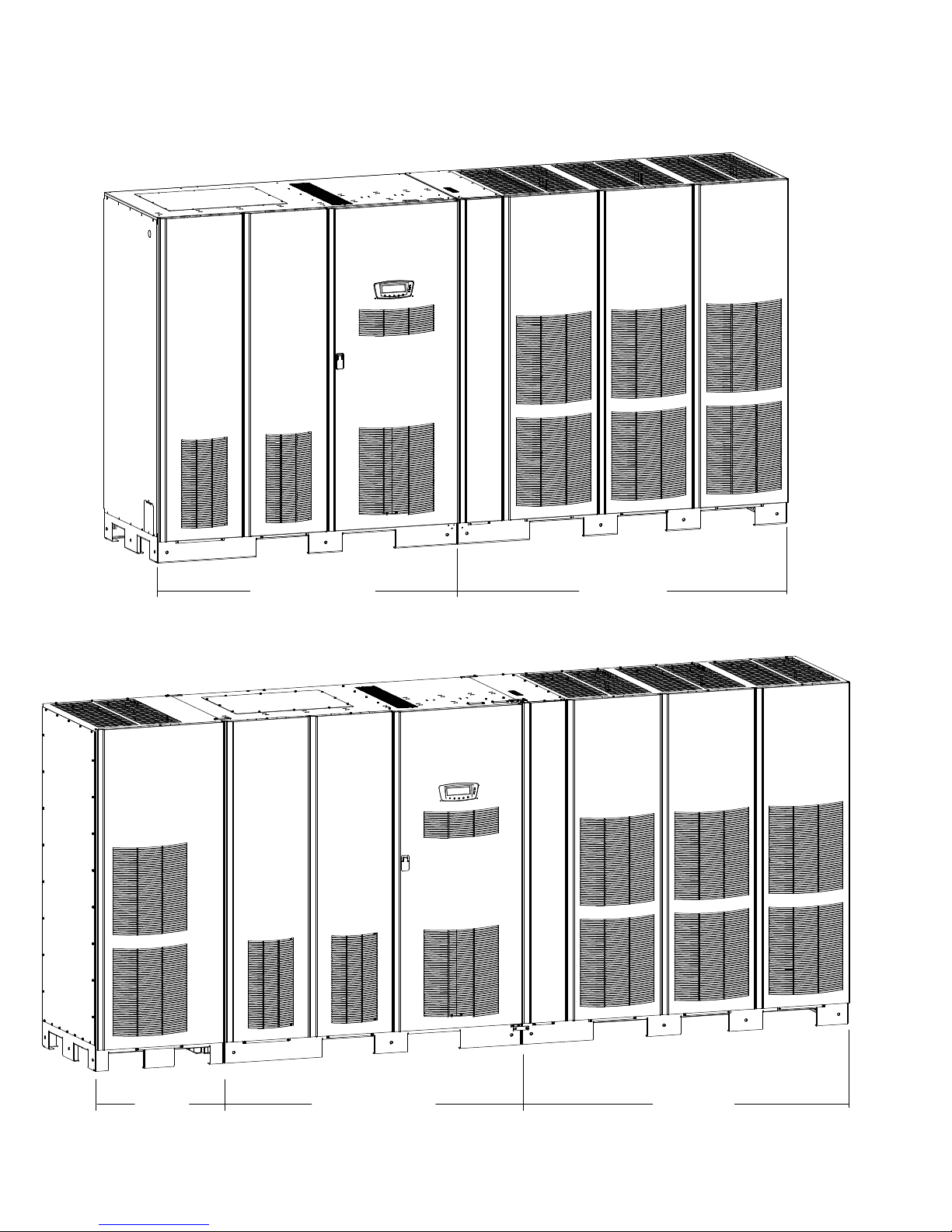
The UPS is housed in a free‐standing cabinet, divided into two sections to facilitate
shipping. The sections match in style and color and have safety shields behind the
door and front panels for hazardous voltage protection. The FI-UPM matches the UPS
in style and color. Figure 1‐1 shows the Eaton 9395 Three UPM UPS (650–825 kVA).
Figure 1‐2 shows the Eaton 9395 Plus 1 UPS (650–825 kVA) UPS with the FI-UPM.
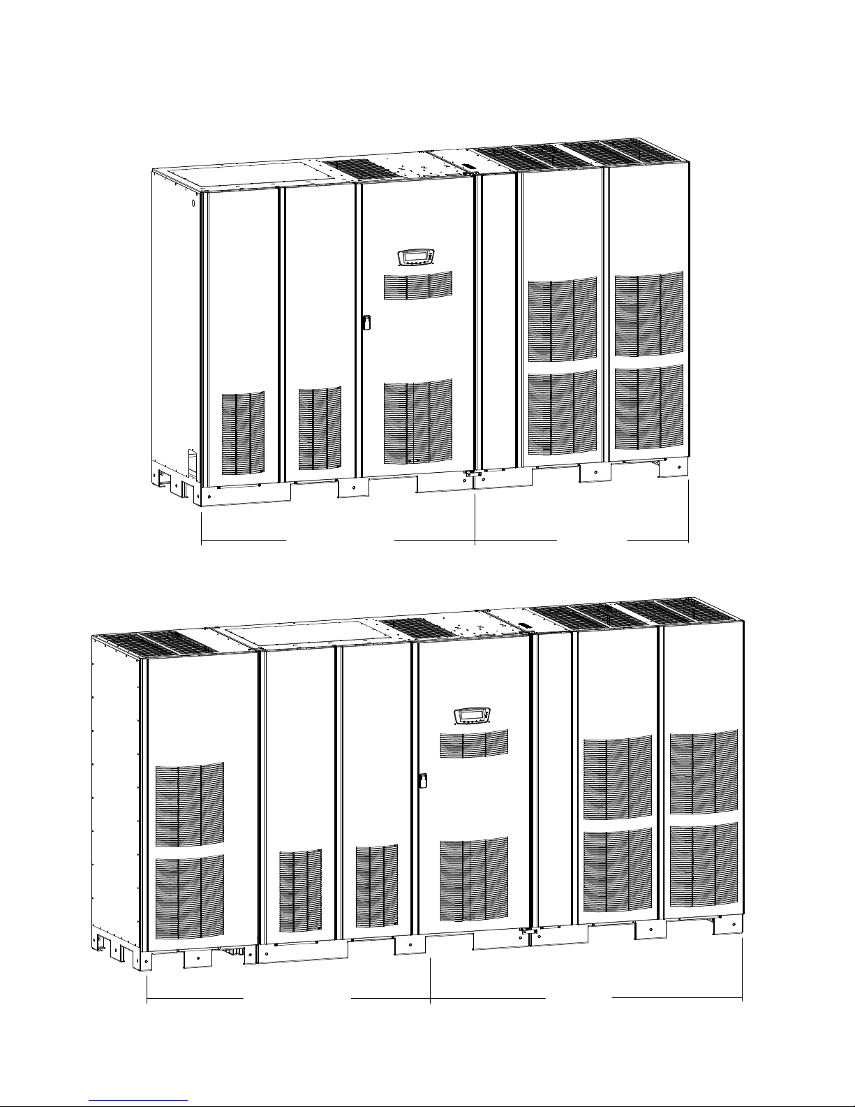
Figure 1‐3 shows the Eaton 9395-825/550 Two UPM UPS (450–550 kVA). Figure 1‐4
shows the Eaton 9395-825/550 Two UPM UPS with the Field Installed UPM
(450–825 kVA).
NOTE Startup and operational checks must be performed by an authorized Eaton Customer Service
Engineer, or the warranty terms specified on page W-1 become void. This service is offered as part of the
sales contract for the UPS. Contact an Eaton service representative in advance (usually a two-week notice is
required) to reserve a preferred startup date.
Eaton 9395 UPS (450–825 kVA) Installation and Operation Manual S 164201725 Rev 4 www.eaton.com/powerquality
1-1
INTRODUCTION
ISBM or IOM SECTION
Figure 1‐1. Eaton 9395 Three UPM UPS (650–825 kVA)
UPM SECTION
FI-UPM
ISBM or IOM SECTION
Figure 1‐2. Eaton 9395 Plus 1 UPS (650–825 kVA) with the Field Installed UPM
1-2
Eaton 9395 UPS (450–825 kVA) Installation and Operation Manual S 164201725 Rev 4 www.eaton.com/powerquality
UPM SECTION
INTRODUCTION
ISBM or IOM SECTION
UPM SECTION
Figure 1‐3. Eaton 9395-825/550 Two UPM UPS (450–550 kVA)
ISBM or IOM SECTION
Figure 1‐4. Eaton 9395-825/550 Two UPM UPS with the Field Installed UPM (450–825 kVA)
Eaton 9395 UPS (450–825 kVA) Installation and Operation Manual S 164201725 Rev 4 www.eaton.com/powerquality
UPM SECTION
1-3

INTRODUCTION
1.1 UPS Standard Features
The UPS has many standard features that provide cost‐effective and consistently
reliable power protection. The descriptions in this section provide a brief overview of
the UPS standard features.
1.1.1 Installation Features
Each UPS section is shipped separately. The sections are mechanically and electrically
joined at the installation site, and can be permanently bolted to the floor.
Power wiring can be routed through the top or bottom of the cabinet with
connections made to easily accessible terminals. Control wiring is routed through the
top of the cabinet and must be installed in accordance with Class 1 wiring methods.
1.1.2 Control Panel
The control panel, located on the front of the UPS, contains a liquid crystal display
(LCD) and pushbutton switches to control the operation of the UPS and to display the
status of the UPS system. See Chapter 7, “UPS Operating Instructions,” for
additional information.
1.1.3 Customer Interface
S Building Alarm Monitoring – Up to five inputs in the UPS are available to connect the
facility's alarm system contacts. Some system configurations may limit the number
of inputs available. The UPS uses these inputs to monitor the building alarms in
addition to the UPS status. See Chapter 8, “Communication,” for additional
information.
S Alarm Contact – One alarm contact is provided for connection to equipment at the
facility, such as a light, an audible alarm, or a computer terminal. The equipment
connected to this contact alerts you to a UPS alarm. See Chapter 8,
“Communication,” for additional information.
S X-Slot Communication Bays – Four communication bays are standard equipment.
One to four optional X-Slot
at any time. X-Slot cards are quickly installed at the front of the UPS and are
hot-pluggable. See Chapter 8, “Communication,” for additional information.
®
connectivity cards can be installed in the UPS module
1.1.4 Advanced Battery Management
A three-stage charging system increases battery service life by optimizing recharge
time, and protects batteries from damage due to high current charging and inverter
ripple currents. Charging at high currents can overheat and damage batteries.
1.1.5 Power Management Software
LanSafe® Power Management Software is bundled as part of the Software Suite CD
shipped with the UPS. See Chapter 8, “Communication,” for additional information.
1-4
Eaton 9395 UPS (450–825 kVA) Installation and Operation Manual S 164201725 Rev 4 www.eaton.com/powerquality

1.2 Options and Accessories
Contact an Eaton sales representative for information about the following options.
1.2.1 Field Installed UPM
A Field Installed UPM (FI-UPM) provides upgradability for the Eaton 9395 825/550 two
UPM UPS. The FI-UPM may be installed at any time in the future when power needs
change. The module cabinet is installed on the left side of the ISBM section and is
wired directly to the UPS. No input or output wiring changes are needed for a capacity
increase if the original installation was wired for increased capacity. Operation
remains the same as the original UPS. Adding the
redundancy if the power requirements are less than the two UPM rating.
1.2.2 Sync Control
An optional Eaton 9395 Sync Control maintains the critical load outputs of two
separate single module Eaton 9395 UPS systems in synchronization. This option
facilitates the uninterrupted transfer of the load from one load bus to another by
means of transfer switches. The Sync Control is housed in a wall‐mounted panel that
can be located between the UPS units for easy wiring.
INTRODUCTION
FI-UPM can also provide N+1
1.2.3 Single-Feed Kit
An optional kit is available for converting the dual-feed rectifier and bypass inputs to a
single-feed configuration. The kit consists of jumpers and bus bar extensions for each
phase, and the hardware required for installation.
1.2.4 Separate Rectifier Input
The UPS can be supplied with separate rectifier inputs for each UPM. Separate inputs
provide increased flexibility and reliability by allowing multiple input sources to supply
the UPS. Input circuit breaker CB1 is not installed with this configuration. AC input
control to the UPS and each UPM rectifier is to be supplied by the customer.
1.2.5 Distributed Bypass System
There are two types of redundancy: UPS based (based on the number of UPSs) and
UPM based (based on the number of UPMs). Each UPS can contain three to four
UPMs.
A distributed bypass UPS system with two to five UPSs can be installed to provide a
capacity and/or redundant system. This load sharing system provides more capacity
than a single UPS, and can provide backup, depending on the load and configuration.
In addition, when one UPM is taken out of service for maintenance or is not operating
properly, a redundant UPM continues to supply uninterrupted power to the critical
load. A Powerware Hot Sync
connectivity and operational mode control. The distributed bypass system consists of
two to five UPSs each with a parallel CAN card, and a customer-supplied tie cabinet or
load distribution panel to act as a tie point.
®
Controller Area Network (CAN) Bridge Card provides
Eaton 9395 UPS (450–825 kVA) Installation and Operation Manual S 164201725 Rev 4 www.eaton.com/powerquality
All UPSs in the distributed bypass system must contain the same number of UPMs.
Mixed UPS kVA ratings are not permitted.
1-5

INTRODUCTION
The tie cabinet must contain Module Output Breakers (MOBs) with dual auxiliary
contacts for control of the system. Without dual auxiliary MOBs, UPMs are not
allowed to go to bypass individually during servicing. All UPMs will go to bypass
instead of just the UPM needing service, decreasing critical load protection. With dual
auxiliary MOBs, one UPM can be bypassed while the remaining UPMs support the
load as long as the remaining UPMs have the capacity to do so.
1.2.6 Input Output Module Configuration
The UPS can be supplied in an Input Output Module (IOM) configuration without the
bypass input connections, the static switch, the motorized wraparound bypass
breaker, and the backfeed protection contactor. This configuration is primarily used in
multiple UPS parallel systems that do not need a bypass for each UPS and use a
separate System Bypass Module (SBM) to provide system bypass capabilities.
1.2.7 Continuous Static Switch
A continuous static switch can be supplied in place of the momentary static switch to
provide transfer of the load from the inverter to the bypass source in the event the
inverter become unavailable. The continuous static switch eliminates the need for an
additional motorized wraparound bypass breaker.
1.2.8 Inherent Redundancy
To deliver greater reliability, the Eaton 9395 UPS can be configured by an authorized
Eaton Customer Service Engineer for inherent redundancy. When configured, the
UPS automatically becomes redundant if the load is at or below the capacity of the
UPMs minus the capacity of one UPM. Under normal conditions the UPMs in the
UPS share the load equally. If one or more UPMs becomes unavailable and the load is
at or below the capacity of remaining UPMs, the remaining UPMs supply the load
instead of transferring to bypass.
If the capacity of the UPMs falls below the redundancy level or the load increases
above redundancy level, but is still able to maintain the load, a loss of redundancy
alarm is sounded. If the load exceeds the capacity of remaining UPMs, the UPS
transfers to bypass.
1.2.9 Energy Saver System and High Alert Modes
NOTE Energy Saver System mode requires the UPS to be factory built with a Continuous Static Switch
(CSS). See Table 1‐1 for applicable configuration.
NOTE The Variable Module Management System and Energy Saver System modes are mutually exclusive.
As a subset of Online mode, the Energy Saver System (ESS)mode maximizes
efficiency by eliminating unnecessary power conversion when the commercial power
source is within acceptable voltage and frequency limits. In this mode, the UPS is
actively monitoring the critical bus and instantly and seamlessly transitions to
double-conversion mode (inverter online) if a commercial electrical power brownout,
blackout, overvoltage, undervoltage, or out‐of‐tolerance frequency condition occurs.
In High Alert mode the unit transfers from ESS mode to double-conversion mode or if
in double-conversion mode remains in double-conversion mode for a default time
period of one hour. High Alert mode allows the user to place the unit in
double-conversion mode when outside conditions could cause a power disturbance.
At the completion of the time period, the unit defaults back to ESS mode. If the High
Alert command is received during the time period, the timer will be restarted.
1-6
Eaton 9395 UPS (450–825 kVA) Installation and Operation Manual S 164201725 Rev 4 www.eaton.com/powerquality

INTRODUCTION
1.2.10 Variable Module Management System and High Alert Modes
NOTE The Variable Module Management System and Energy Saver System modes are mutually exclusive.
The Variable Module Management System (VMMS) mode maintains UPM
redundancy and achieves higher efficiencies by intelligently controlling the UPM’s
load level. The efficiency rating for each UPM is highest when loads are greater than
50% of the system rating. Therefore, shifting the load to fewer UPMs can achieve
higher efficiencies when the UPS load is lighter.
In VMMS mode, the UPS is actively monitoring the critical bus and UPMs are
available to assume load in less than 2 ms to respond to load changes.
The VMMS feature has three configurable modes of operation: Online mode, Online
mode with VMMS, and High Alert mode. All modes are selectable from the front
panel.
VMMS mode supports both distributed bypass and SBM parallel configurations.
In High Alert mode, all idle UPMs go online for one hour. At the completion of the
hour, the UPS defaults back to VMMS mode. If the High Alert command is received
during the one hour, the one hour timer will be restarted.
1.2.11 Monitoring and Communication
S Remote Monitor Panel II (RMP II) – An optional RMP II contains backlit status
indicators and a local horn, allowing monitoring of the operational status and alarm
condition of the UPS from virtually any location within the facility.
S Relay Interface Module II (RIM II) – An optional RIM II uses relay contact closures to
indicate the UPS operating status and alarm condition.
S Supervisory Contact Module II (SCM II) – An optional SCM II establishes an interface
between the UPS system equipment and the customer's monitor.
S X-Slot Cards – Optional X-Slot cards support several protocols, such as SNMP,
HTTP, IBM
®
AS/400®, and Modbus®.
S eNotify Remote Monitoring and Diagnostics Service – An optional service that provides
24/7 remote monitoring of 43 alarms, temperature/humidity and battery charge
information, daily heartbeat check, and monthly report. The service also provides
customer notification of significant alarms, remote diagnostics, and dispatch of
technicians. A ConnectUPS -X Web/SNMP Card is required in an X-Slot
communication bay. An optional Environmental Monitoring Probe (EMP) is required
for temperature/humidity monitoring.
See Chapter 8, “Communication,” for additional information on monitoring and
communication features.
t
Eaton 9395 UPS (450–825 kVA) Installation and Operation Manual S 164201725 Rev 4 www.eaton.com/powerquality
1-7

INTRODUCTION
1.3 Battery System
Although not provided with the UPS, a battery system is required to provide
emergency short-term backup power to safeguard operation during brownouts,
blackouts, and other power interruptions. The battery system should be equipped
with lead‐acid batteries. An external battery disconnect switch must be used.
The UPMs may be powered with either a common or separate battery system. In a
common battery system, single and multiple UPMs are powered from one common
battery source. In a separate battery system, multiple UPMs are each powered from
separate battery sources.
UPMs in distributed bypass and parallel systems must use a separate battery system.
A supplemental 48 Vdc shunt trip signal for the battery disconnect device is provided
by the UPS, but is not required for normal operation.
1.4 Basic System Configurations
The following basic UPS system configurations are possible:
S Single UPS with three common battery UPMs and a standalone common battery
system with a battery disconnect
S Single Plus 1 UPS with three common battery UPMs, a common battery FI-UPM,
and a standalone common battery system with a battery disconnect
S Single 825/550 UPS with two common battery UPMs and a standalone common
battery system with a battery disconnect
S Single UPS with three separate battery UPMs and a standalone separate battery
system with a battery disconnect for each UPM
S Single Plus 1 UPS with three separate battery UPMs, a separate battery FI-UPM,
and a standalone separate battery system with a battery disconnect for each UPM
S Single 825/550 UPS with two separate battery UPMs and a standalone separate
battery system with a battery disconnect for each UPM
S Distributed bypass system with two to five UPSs and a customer-supplied
tie cabinet
The UPS system configuration can be enhanced by adding optional accessories such
as a Remote Emergency Power-off (REPO) control, RMP II, or X-Slot communication
cards.
The base configuration (first two digits of the configuration number) for the UPS are
listed in Table 1‐1. The configuration number can be found on the rating label
mounted on the internal safety shield panel inside the front door.
Table 1‐1. Base Configuration Digits
825 kVA ISBM, two UPM, Continuous Static Switch (CSS) CS
825 kVA ISBM, three UPM, Momentary Static Switch (MSS) CU
825 kVA ISBM, four UPM (Plus 1), MSS CV
825 kVA ISBM, three UPM, Continuous Static Switch (CSS) CE
825 kVA ISBM, four UPM (Plus 1), CSS CG
825 kVA IOM, three UPM CN
825 kVA IOM, four UPM (Plus 1) CP
1-8
Eaton 9395 UPS (450–825 kVA) Installation and Operation Manual S 164201725 Rev 4 www.eaton.com/powerquality
Configuration Base Digits

1.5 Using This Manual
This manual describes how to install and operate the Eaton 9395 450–825 kVA UPS.
Read and understand the procedures described in this manual to ensure trouble-free
installation and operation. In particular, be thoroughly familiar with the REPO
procedure (see paragraph 7.3.25 on page 7-29).
The information in this manual is divided into sections and chapters. The system,
options, and accessories being installed dictate which parts of this manual should be
read. At a minimum, Chapters 1 through 4 and Chapter 7 should be examined.
Read through each procedure before beginning the procedure. Perform only those
procedures that apply to the UPS system being installed or operated.
1.6 Conventions Used in This Manual
This manual uses these type conventions:
S Bold type highlights important concepts in discussions, key terms in procedures,
and menu options, or represents a command or option that you type or enter at a
prompt.
S Italic type highlights notes and new terms where they are defined.
S Screen type represents information that appears on the screen or LCD.
INTRODUCTION
Icon Description
Information notes call attention to important features or instructions.
[Keys] Brackets are used when referring to a specific key, such as [Enter] or [Ctrl].
In this manual, the term UPS refers only to the UPS cabinet and its internal elements.
The term UPS system refers to the entire power protection system – the UPS
cabinet, the battery system, and options or accessories installed.
Eaton 9395 UPS (450–825 kVA) Installation and Operation Manual S 164201725 Rev 4 www.eaton.com/powerquality
1-9
INTRODUCTION
1.7 Symbols, Controls, and Indicators
The following are examples of symbols used on the UPS or accessories to alert you to
important information:
RISK OF ELECTRIC SHOCK - Observe the warning associated with the risk of electric
shock symbol.
CAUTION: REFER TO OPERATOR'S MANUAL - Refer to your operator's manual for
additional information, such as important operating and maintenance instructions.
1.8 For More Information
This symbol indicates that you should not discard the UPS or the UPS batteries in the
trash. This product contains sealed, lead‐acid batteries and must be disposed of
properly. For more information, contact your local recycling/reuse or hazardous waste
center.
This symbol indicates that you should not discard waste electrical or electronic
equipment (WEEE) in the trash. For proper disposal, contact your local recycling/reuse
or hazardous waste center.
Refer to the Eaton 9390 and 9395 Sync Control Installation and Operation Manual for
the following additional information:
S Installation instructions, including site preparation, planning for installation, and
wiring and safety information. Detailed illustrations of the cabinet with dimensional
and connection point drawings are provided.
S Operation, including controls, functions of the standard and optional features,
procedures for using with the UPS, and information about maintenance.
Refer to the Eaton 9395 Field Installed UPM Mechanical Installation Manual for the
following additional information:
S Mechanical installation instructions, including site preparation, planning for
mechanical installation, and safety information.
S Detailed illustrations of the cabinet, including dimension and pallet removal
drawings.
Visit www.eaton.com/powerquality or contact an Eaton service representative for
information on how to obtain copies of these manuals.
1-10
Eaton 9395 UPS (450–825 kVA) Installation and Operation Manual S 164201725 Rev 4 www.eaton.com/powerquality

1.9 Getting Help
INTRODUCTION
If help is needed with any of the following:
S Scheduling initial startup
S Regional locations and telephone numbers
S A question about any of the information in this manual
S A question this manual does not answer
Please call the Help Desk at:
United States:
1-800-843-9433 or 1-919-870-3028
Canada: 1-800-461-9166 ext 260
All other countries: Call your local service representative
Eaton 9395 UPS (450–825 kVA) Installation and Operation Manual S 164201725 Rev 4 www.eaton.com/powerquality
1-11

INTRODUCTION
This page intentionally left blank.
1-12
Eaton 9395 UPS (450–825 kVA) Installation and Operation Manual S 164201725 Rev 4 www.eaton.com/powerquality

Chapter 2 Safety Warnings
Figure
IMPORTANT SAFETY INSTRUCTIONS
SAVE THESE INSTRUCTIONS
This manual contains important instructions that should be followed during installation and maintenance of
the UPS and batteries. Read all instructions before operating the equipment and save this manual for future
reference.
The UPS is designed for industrial or computer room applications, and contains safety shields behind the
door and front panels. However, the UPS is a sophisticated power system and should be handled with
appropriate care.
This UPS contains LETHAL VOLTAGES. All repairs and service should be performed by AUTHORIZED
SERVICE PERSONNEL ONLY. There are NO USER SERVICEABLE PARTS inside the UPS.
S The UPS is powered by its own energy source (batteries). The output terminals may carry live voltage
even when the UPS is disconnected from an AC source.
S To reduce the risk of fire or electric shock, install this UPS in a temperature and humidity controlled,
indoor environment, free of conductive contaminants. Ambient temperature must not exceed 40°C
(104°F). Do not operate near water or excessive humidity (95% maximum). The system is not intended for
outdoor use.
S Ensure all power is disconnected before performing installation or service.
S Batteries can present a risk of electrical shock or burn from high short‐circuit current. The following
precautions should be observed: 1) Remove watches, rings, or other metal objects; 2) Use tools with
insulated handles; 3) Do not lay tools or metal parts on top of batteries; 4) Wear rubber gloves and boots.
S ELECTRIC ENERGY HAZARD. Do not attempt to alter any UPS or battery wiring or connectors. Attempting
to alter wiring can cause injury.
S Do not open or mutilate batteries. Released electrolyte is harmful to the skin and eyes. It may be toxic.
D A N G E R
W A R N I N G
Eaton 9395 UPS (450–825 kVA) Installation and Operation Manual S 164201725 Rev 4 www.eaton.com/powerquality
C A U T I O N
S Installation or servicing should be performed by qualified service personnel knowledgeable of UPS and
battery systems, and required precautions. Keep unauthorized personnel away from equipment. Consider
all warnings, cautions, and notes before installing or servicing equipment. DO NOT DISCONNECT the
batteries while the UPS is in Battery mode.
S Replace batteries with the same number and type of batteries as originally installed with the UPS.
S Disconnect the charging source prior to connecting or disconnecting terminals.
S Determine if the battery is inadvertently grounded. If it is, remove the source of the ground. Contacting
any part of a grounded battery can cause a risk of electric shock. An electric shock is less likely if you
disconnect the grounding connection before you work on the batteries.
S Proper disposal of batteries is required. Refer to local codes for disposal requirements.
S Do not dispose of batteries in a fire. Batteries may explode when exposed to flame.
S Keep the UPS door closed and front panels installed to ensure proper cooling airflow and to protect
personnel from dangerous voltages inside the unit.
S Do not install or operate the UPS system close to gas or electric heat sources.
2-1

SAFETY WARNINGS
S The operating environment should be maintained within the parameters stated in this manual.
S Keep surroundings uncluttered, clean, and free from excess moisture.
S Observe all DANGER, CAUTION, and WARNING notices affixed to the inside and outside of the
equipment.
C A U T I O N
To prevent damage to the wiring channel and wiring in the UPS cabinet base when lifting or moving the
cabinet:
S Lift and move the cabinet using only the front or rear forklift slots.
S Verify that the forklift forks are in a horizontal position before inserting them into the forklift slots.
DO NOT angle fork tips upward.
S Insert the forks all the way through the base. DO NOT insert forks partially into the base to move the
cabinet.
S Forks may be partially inserted into the front or rear forklift slots for minor positioning if the forks are
kept in a horizontal position with no upward angling.
S DO NOT use the forklift slots on the end of the cabinet to move the cabinet.
S End forklift slots may be used for minor positioning if the forks are kept in a horizontal position with no
upward angling.
If these instructions are not followed, damage to the wiring channel and wiring will occur.
A V E R T I S S E M E N T !
S Les batteries peuvent présenter un risque de décharge électrique ou de brûlure par des courts‐circuits de
haute intensité. Prendre les précautions nécessaires.
S Pour le replacement, utiliser le même nombre et modéle des batteries.
A T T E N T I O N !
S Une mise au rebut réglementaire des batteries est obligatoire. Consulter les règlements en vigueur dans
votre localité.
S Ne jamais jeter les batteries au feu. L'exposition aux flammes risque de les faire exploser.
2-2
Eaton 9395 UPS (450–825 kVA) Installation and Operation Manual S 164201725 Rev 4 www.eaton.com/powerquality

Section I
Installation
Eaton 9395 UPS (450–825 kVA) Installation and Operation Manual S 164201725 Rev 4 www.eaton.com/powerquality
2-1

2-2
Eaton 9395 UPS (450–825 kVA) Installation and Operation Manual S 164201725 Rev 4 www.eaton.com/powerquality

Chapter 3 UPS Installation Plan and Unpacking
Figure
Use the following basic sequence of steps to install the UPS:
1. Create an installation plan for the UPS system (Chapter 3).
2. Prepare your site for the UPS system (Chapter 3).
3. Inspect and unpack the UPS sections (Chapter 3).
4. Unload and install the UPS sections, and wire the system (Chapter 4).
5. Install features, accessories, or options, as applicable (Chapter 5).
6. Complete the Installation Checklist (Chapter 4).
7. Have authorized service personnel perform preliminary operational checks and
start up the system.
NOTE Startup and operational checks must be performed by an authorized Eaton Customer Service
Engineer, or the warranty terms specified on page W-1 become void. This service is offered as part of the
sales contract for the UPS. Contact an Eaton service representative in advance (usually a two-week notice is
required) to reserve a preferred startup date.
3.1 Creating an Installation Plan
Before installing the UPS system, read and understand how this manual applies to the
system being installed. Use the procedures and illustrations in paragraph 3.2 and
Chapter 4 to create a logical plan for installing the system.
3.2 Preparing the Site
For the UPS system to operate at peak efficiency, the installation site should meet the
environmental parameters outlined in this manual. If the UPS is to be operated at an
altitude higher than 1500m (5000 ft), contact an Eaton service representative for
important information about high altitude operation. The operating environment must
meet the weight, clearance, and environmental requirements specified.
3.2.1 Environmental and Installation Considerations
The UPS system installation must meet the following guidelines:
S The system must be installed on a level floor suitable for computer or electronic
equipment.
S The system must be installed in a temperature and humidity controlled indoor area
free of conductive contaminants.
Failure to follow guidelines may void your warranty.
The UPS equipment operating environment must meet the weight requirements
shown in Table 3‐1 and the size requirements shown in Figure 3‐1 through
Figure 3‐15. Dimensions are in millimeters (inches).
Eaton 9395 UPS (450–825 kVA) Installation and Operation Manual S 164201725 Rev 4 www.eaton.com/powerquality
Table 3‐1 does not include the weight of the Field Installed UPM (FI-UPM). For
FI-UPM weights and dimensions, refer to the Eaton 9395 Field Installed UPM
Mechanical Installation Manual, listed in paragraph 1.8 on page 1-10.
3-1

UPS INSTALLATION PLAN AND UNPACKING
Table 3‐1. UPS Cabinet Weights
Model Section
Weight
kg (lb)
Shipping Installed
Eaton 9395-825/450
Eaton 9395-825/500
Eaton 9395-825/550
Eaton 9395-825/650
Eaton 9395-825/750
Eaton 9395-825/825
NOTE MSS = Momentary Static Switch; CSS = Continuous Static Switch; IOM = Input Output Module
ISBM (CSS) 797 (1757) 729 (1607)
UPM (Two UPM) 1159 (2556) 1093 (2410)
ISBM (CSS) 797 (1757) 729 (1607)
UPM (Two UPM) 1159 (2556) 1093 (2410)
ISBM (CSS) 797 (1757) 729 (1607)
UPM (Two UPM) 1159 (2556) 1093 (2410)
ISBM (MSS) 652 (1437) 588 (1297)
ISBM (CSS) 797 (1757) 729 (1607)
IOM 599 (1321) 490 (1181)
UPM (Three UPM) 1699 (3745) 1628 (3590)
ISBM (MSS) 652 (1437) 588 (1297)
ISBM (CSS) 797 (1757) 729 (1607)
IOM 599 (1321) 490 (1181)
UPM (Three UPM) 1699 (3745) 1628 (3590)
ISBM (MSS) 652 (1437) 588 (1297)
ISBM (CSS) 797 (1757) 729 (1607)
IOM 599 (1321) 490 (1181)
UPM (Three UPM) 1699 (3745) 1628 (3590)
The UPS cabinet uses forced air cooling to regulate internal component temperature.
Air inlets are in the front of the cabinet and outlets are in the top. Allow clearance in
front of and above each cabinet for proper air circulation. The clearances required
around the UPS cabinet are shown in Table 3‐2.
Table 3‐2. UPS Cabinet Clearances
From Top of Cabinet 457.2 mm (18”) minimum clearance for ventilation
From Front of Cabinet 914.4 mm (36”) working space
From Back of Cabinet None Required
From Right Side of
Cabinet
From Left Side of Cabinet None Required
3-2
Eaton 9395 UPS (450–825 kVA) Installation and Operation Manual S 164201725 Rev 4 www.eaton.com/powerquality
152.4 mm (6”) working space
 Loading...