

Eaton 150 VCP-WL, 50 VCP-WL, 75 VCP-WL Instructions For Installation, Operation And Maintenance
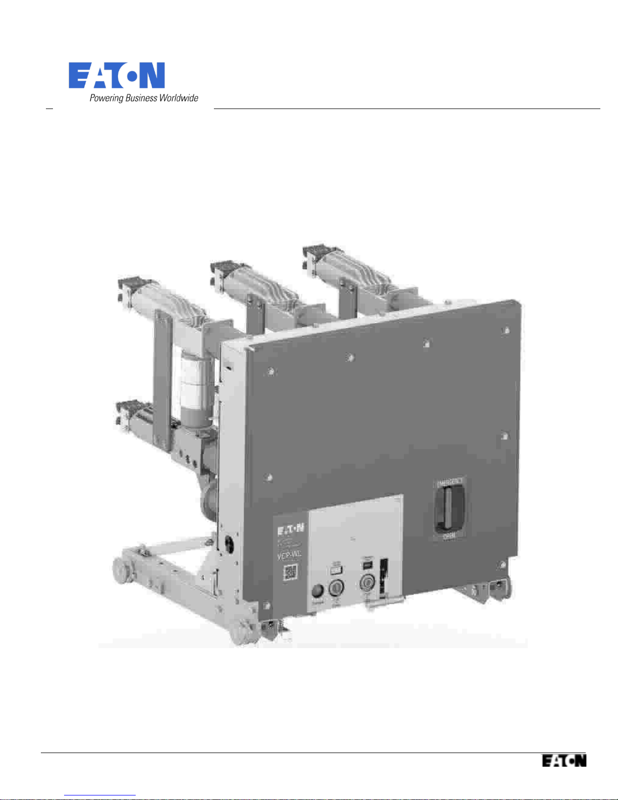
Instructions for Installation, Operation and Maintenance
IB131021EN
of Type VCP-WL Vacuum Circuit Breakers
Effective Mar 2018

THIS PAGE INTENTIONALLY LEFT BLANK

Effective Mar 2018
IB131021EN

IB13 1020EN Pag e ii
WARNING
IMPROPERLY INSTALLING OR MAINTAINING THESE
PRODUCTS CAN RESULT IN DEATH, SERIOUS
PERSONAL INJURY, OR PROPERTY DAMAGE.
READ AND UNDERSTAND THESE INSTRUCTIONS
BEFORE ATTEMPTING ANY UNPACKING, ASSEMBLY,
OPERATION OR MAINTENANCE OF THE CIRCUIT
BREAKERS.
INSTALLATION OR MAINTENANCE SHOULD BE
ATTEMPTED ONLY BY QUALIFIED PERSONNEL. THIS
INSTRUCTION BOOK SHOULD NOT BE CONSIDERED
ALL INCLUSIVE REGARDING INSTALLATION OR
MAINTENANCE PROCEDURES. IF FURTHER
INFORMATION IS REQUIRED, YOU SHOULD CONTACT
EATON.
WARNING
THE CIRCUIT BREAKER ELEMENTS DESCRIBED IN
THIS BOOK ARE DESIGNED AND TESTED TO
OPERATE WITHIN THEIR NAMEPLATE RATINGS.
OPERATION OUTSIDE OF THESE RATINGS MAY
CAUSE THE EQUIPMENT TO FAIL, RESULTING IN
DEATH, BODILY INJURY AND PROPERTY DAMAGE.
ALL SAFETY CODES, SAFETY STANDARDS AND/OR
REGULATIONS AS THEY MAY BE APPLIED TO THIS
TYPE OF EQUIPMENT MUST BE STRICTLY ADHERED
TO.
THESE CIRCUIT BREAKER ELEMENTS ARE DESIGNED
TO BE INSTALLED PURSUANT TO THE AMERICAN
NATIONAL STANDARDS INSTITUTE (ANSI). SERIOUS
INJURY, INCLUDING DEATH, CAN RESULT FROM
FAILURE TO FOLLOW THE PROCEDURES OUTLINED
IN THIS MANUAL. THESE CIRCUIT BREAKER
ELEMENTS ARE SOLD PURSUANT TO A NONSTANDARD PURCHASING AGREEMENT WHICH LIMITS
THE LIABILITY OF THE MANUFACTURER.
All possible contingencies which may arise during installation, operation or maintenance, and all details and
variations of this equipment do not purport to be covered by these instructions. If further information is desired
by purchaser regarding his particular installation, operation or maintenance of particular equipment, contact an
Eaton representative.
Effective Mar 2018

TABLE OF CONTENTS
SECTION 1: INTRODUCTION....................................................................................................................................................................................1
1-1 PRELIMINARY COMMENTS AND SAFETY PRE- CAUTIONS..................................................................................................................................1
1-2 GENERAL INFORMATION...................................................................................................................................................................................1
1-3 TYPE VCP-WL VACUUM CIRCUIT BREAKER ELEMENT RATINGS.........................................................................................................................2
1-4 OUTLINES AND DIMENSIONS.............................................................................................................................................................................3
SECTION 2: SAFE PRACTICES...................................................................................................................................................................................5
2-1 RECOMMENDATIONS.........................................................................................................................................................................................5
SECTION 3: RECEIVING, HANDLING AND STORAGE..................................................................................................................................................6
3-1 GENERAL............................................................................................................................................................................................................6
3-2 RECEIVING..........................................................................................................................................................................................................6
3-3 HANDLING..........................................................................................................................................................................................................6
3-4 STORAGE............................................................................................................................................................................................................6
3-5 TOOLS AND ACCESSORIES..................................................................................................................................................................................7
3-6 TYPE VCP-WL VACUUM CIRCUIT BREAKER ELEMENT WEIGHTS........................................................................................................................7
SECTION 4: INITIAL INSPECTION AND INSTALLATION............................................................................................................................................ 14
4-1 INTRODUCTION................................................................................................................................................................................................14
4-2 VACUUM INTERRUPTER INTEGRITY.................................................................................................................................................................14
4-3 INSULATION.....................................................................................................................................................................................................14
4-4 PRIMARY CIRCUIT RESISTANCE........................................................................................................................................................................14
4-5 NAMEPLATE.....................................................................................................................................................................................................14
4-6 ELECTRICAL OPERATION AND MECHANICAL OPEN CHECK..............................................................................................................................14
4-7 CIRCUIT BREAKER/STRUCTURE INTERFACING.................................................................................................................................................21
SECTION 5: DESCRIPTION AND OP E R ATIO N ........................................................................................................................................................23
5-1 INTRODUCTION................................................................................................................................................................................................23
5-2 INTERRUPTER ASSEMBLY.................................................................................................................................................................................23
5-3 ELECTROMAGNETIC MECHANISM...................................................................................................................................................................26
5-4 CONTROL SCHEMES.........................................................................................................................................................................................29
5-5 INTERLOCKS AND INTERFACING......................................................................................................................................................................29
5-6 LEVERING MECHANISM...................................................................................................................................................................................29
5-7 OPERATIONS COUNTER....................................................................................................................................................................................30
5-8 GROUND CONTACT..........................................................................................................................................................................................30
5-9 MOC AND TOC SWITCH OPERATIONS..............................................................................................................................................................30
SECTION 6: INSPECTION, MAINTENANCE A N D TR O U BLES H O OTI N G .................................................................................................................31
6-1 INTRODUCTION................................................................................................................................................................................................31
6-2 FREQUENCY OF INSPECTION AND MAINTENANCE..........................................................................................................................................31
6-3 INSPECTION AND MAINTENANCE PROCEDURES.............................................................................................................................................33
6-4 VACUUM INTERRUPTER INTEGRITY TEST.........................................................................................................................................................34
6-5 CONTACT EROSION AND WIPE.........................................................................................................................................................................35
6-6 INSULATION....................................................................................................................................................................................................35
6-7 INSULATION INTEGRITY CHECK........................................................................................................................................................................35
6-8 PRIMARY CIRCUIT RESISTANCE CHECK.............................................................................................................................................................36
6-9 MECHANISM CHECK.........................................................................................................................................................................................36
6-10 LUBRICATION...................................................................................................................................................................................................36
6-11 TROUBLESHOOTING CHART (CONTINUED NEXT PAGE).........................................................................................................................................37
6-11 TROUBLESHOOTING CHART (CONTINUED)..........................................................................................................................................................38
6-12 END OF LIFE PROCEDURES...............................................................................................................................................................................39
6-13 FAILURE REPORTING........................................................................................................................................................................................39
6-14 REPLACEMENT PARTS......................................................................................................................................................................................39

Pag e iv IB13 1021EN
FIGURES
FIGURE 1-1 TYPE VCP-WL CIRCUIT BREAKER OUTLINES AND DIMENSIONS..........................................................................................3
FIGURE 3-1 TYPICAL VCP-WL TOOLS AND ACCESSORIES......................................................................................................................8
FIGURE 3-2 TYPICAL FRONT VIEW VCP-WL VACUUM CIRCUIT BREAKER .....................9
FIGURE 3-3 TYPICAL VCP-WL VACUUM CIRCUIT BREAKER ELEMENT WITH FRONT COVER REMOVED.................................................10
FIGURE 3-4 VCP-WL MECHANISM DETAILS.......................................................................................................................................11
FIGURE 3-5 TYPICAL REAR VIEW VCP-WL VACUUM CIRCUIT BREAKER ELEMENT................................................................................12
FIGURE 3-6 TYPICAL VCP-WL VACUUM CIRCUIT BREAKER FRONT COVER ARRANGEMENT................................................................. 13
FIGURE 4-1A INSERTION OF THE DRAWOUT EXTENSION RAILS.........................................................................................................15
FIGURE 4-1B LIFTING AND SETTING THE BREAKER IN THE HOUSING..................................................................................................15
FIGURE 4-1C BPI PAN ASSEMBLY......................................................................................................................................................17
FIGURE 4-2 ENGAGING EXTENSION RAILS IN A LOWER CIRCUIT BREAKER COMPARTMENT................................................................19
FIGURE 4-3 TYPICAL VCP-WL CIRCUIT BREAKER BOTTOM VIEW........................................................................................................20
FIGURE 4-4 ENGAGING LEVERING-IN CRANK....................................................................................................................................21
FIGURE 5-1 VCP-WL POLE UNIT AND VACUUM INTERRUPTER...........................................................................................................23
FIGURE 5-2 GRAPHIC REPRESENTATION OF ARC INTERRUPTION.......................................................................................................24
FIGURE 5-3 MEASUREMENT OF CONTACT STROKE...........................................................................................................................25
FIGURE 5-4 LOOSENING THE DRIVE ROD HOUSING JAM NUT............................................................................................................25
FIGURE 5-5 MEASUREMENT OF CONTACT OPEN GAP.......................................................................................................................25
FIGURE 5-5 TYPICAL VCP-WL CONTROL SCHEME..............................................................................................................................29
Effective Mar 2018
IB13 1021EN P ag e v
TABLES
TABLE 1-1 (ANSI STANDARDS) TYPE VCP-WL VACUUM CIRCUIT BREAKER...........................................................................................2
TABLE 3-1 VCP-WL ANSI RATED BREAKER WEIGHTS............................................................................................................................7
TABLE 6.1 TORQUE GUIDELINES.......................................................................................................................................................32
TABLE 6.2 (INSULATION & VACUUM INTEGRITY) TEST VOLTAGE.......................................................................................................34
TABLE 6.3 TYPICAL RESISTANCE MEASUREMENTS.............................................................................................................................36
INTRODUCTIONSECTION 1:
PRELIMINARY COMMENTS AND SAFETY PRE- 1-1
CAUTIONS
This technical document is intended to cover most aspects
associated with the installation, operation and maintenance
of Type VCP-WL Vacuum Circuit Breakers. It is provided
as a guide for authorized and qualified personnel only.
Please refer to the specific WARNING and CAUTION in
Paragraph 1-1.2 before proceeding past Section 1. If
further information is required by the purchaser regarding a
particular installation, application or maintenance activity,
an Eaton representative should be contacted.
WARRANTY AND LIABILITY FORMATION1-1.1
NO WARRANTIES, EXPRESSED OR IMPLIED,
INCLUDING WARRANTIES OF FITNESS FOR A
PARTICULAR PURPOSE OF MERCHANTABILITY, OR
WARRANTIES ARISING FROM COURSE OF DEALING
OR USAGE OF TRADE, ARE MADE REGARDING THE
INFORMATION, RECOMMENDATIONS AND
DESCRIPTIONS CONTAINED HEREIN. In no event will
Eaton be responsible to the purchaser or user in contract,
in tort (including negligence), strict liability or otherwise for
any special, indirect, incidental or consequential damage
or loss whatsoever, including but not limited to damage or
loss of use of equipment, plant or power system, cost of
capital, loss of power, additional expenses in the use of
existing power facilities, or claims against the purchaser or
user by its customers resulting from the use of the
information and descriptions contained herein.
WARNING
THE WARNINGS AND CAUTIONS INCLUDED AS PART
OF THE PROCEDURAL STEPS IN THIS DOCUMENT
ARE FOR PERSONNEL SAFETY AND PROTECTION OF
EQUIPMENT FROM DAMAGE. AN EXAMPLE OF A
TYPICAL WARNING LABEL HEADING IS SHOWN
ABOVE IN REVERSE TYPE TO FAMILIARIZE
PERSONNEL WITH THE STYLE OF PRESENTATION.
THIS WILL HELP TO INSURE THAT PERSONNEL ARE
ALERT TO WARNINGS, WHICH MAY APPEAR
THROUGHOUT THE DOCUMENT. IN ADDITION,
CAUTIONS ARE ALL UPPER CASE AND BOLDFACE
AS SHOWN BELOW.
CAUTION
COMPLETELY READ AND UNDERSTAND THE
MATERIAL PRESENTED IN THIS DOCUMENT BEFORE
ATTEMPTING INSTALLATION, OPERATION OR
APPLICATION OF THE EQUIPMENT. IN ADDITION,
ONLY QUALIFIED PERSONS SHOULD BE PERMIT-TED
TO PERFORM ANY WORK ASSOCIATED WITH THE
EQUIPMENT. ANY WIRING INSTRUCTIONS
PRESENTED IN THIS DOCUMENT MUST BE
FOLLOWED PRECISELY. FAILURE TO DO SO COULD
CAUSE PERMANENT EQUIPMENT DAMAGE.
1-2 GENERAL INFORMATION
1-1.2 SAFETY PRECAUTIONS
All safety codes, safety standards and/or regulations must
be strictly observed in the installation, operation and
maintenance of this device.
Effective Mar 2018
The purpose of this book is to provide instructions for
unpacking, storage, use, operation and maintenance of
Type VCP-WL Vacuum Circuit Breakers. These circuit
breakers are horizontal drawout type removable
interrupting elements designed for use in VacClad-W MetalClad Switchgear and appropriate VCP-WL modules. The
Type VCP-WL Vacuum Circuit Breakers are designed to
operate as a roll-in replacement for Type VCP-W Vacuum
Circuit Breakers. They provide reliable control and
protection for medium voltage electrical equipment and

Pag e ii IB13 1021EN
circuits. All VCP-WL circuit breaker elements are designed
to ANSI Standards for reliable performance, ease of
handling and simplified maintenance.
WARNING
SATISFACTORY PERFORMANCE OF THESE
BREAKERS AND OR MINIMOD IS CONTINGENT UPON
PROPER APPLICATION, CORRECT INSTALLATION
AND ADEQUATE MAINTENANCE. THIS INSTRUCTION
BOOK MUST BE CAREFULLY READ AND FOLLOWED
IN ORDER TO OBTAIN OPTIMUM PERFORMANCE FOR
LONG USEFUL LIFE OF THE MINIMOD. EQUIPMENT
TO FAIL, RESULTING IN DEATH, BODILY INJURY AND
PROPERTY DAMAGE.
ALL SAFETY CODES, SAFETY STANDARDS AND/OR
REGULATIONS AS THEY MAY BE APPLIED TO THIS
TYPE OF EQUIPMENT MUST BE STRICTLY ADHERED
TO.
Effective Mar 2018
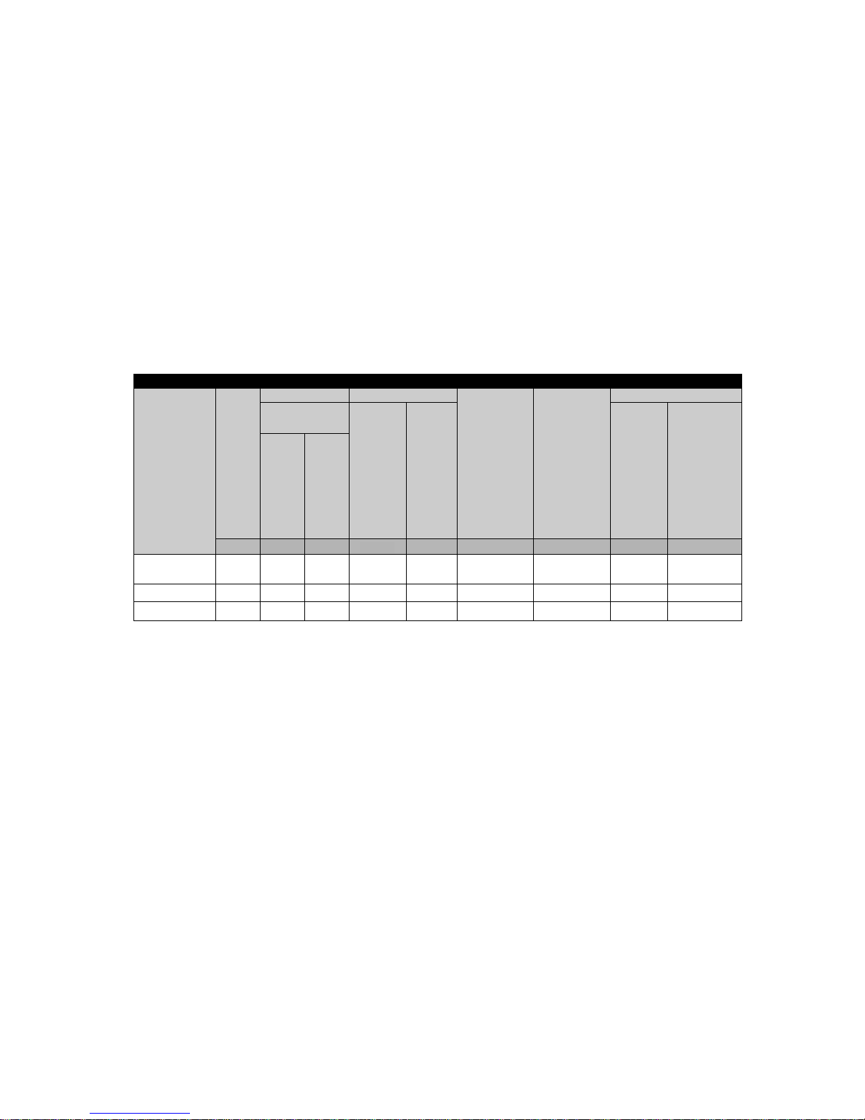
TYPE VCP-WL VACUUM CIRCUIT BREAKER ELEMENT RATINGS1-3
Rated Values
Circuit
Breaker
Type
Nominal
Voltage
Class
Insulation Level Current
Interrupting
Time
Permissible
Tripping
Delay
Y
Current Values
Withstand Test
Voltage
Continuous
Current
at 60 Hz
Short
Circuit
Current
(at Rated
Max. kV)
I
Closing
and
Latching
Capability
2.7 K
Times
Rated
Short
Circuit
Current
Closing
and
Latching
Capability
Momentary
1.6 K
Times
Rated
Short
Circuit
Current
Power
Frequency
(1 Min.)
Impulse
kV kV rms Amperes kA rms Cycles Seconds kA Peak kA rms
150 VCP-WL 15 36 95 1200 25 3 or 5 2 65 39
75 VCP-WL 8.25 36 95 1200 25 3 or 5 2 65 39
50 VCP-WL 4.76 36 95 1200 25 3 or 5 2 65 39
Table 1-1 (ANSI Standards) Type VCP-WL Vacuum Circuit Breaker Through 15 kV Rated Symmetrical Current Basis
Identification
Pag e iv IB13 1021EN
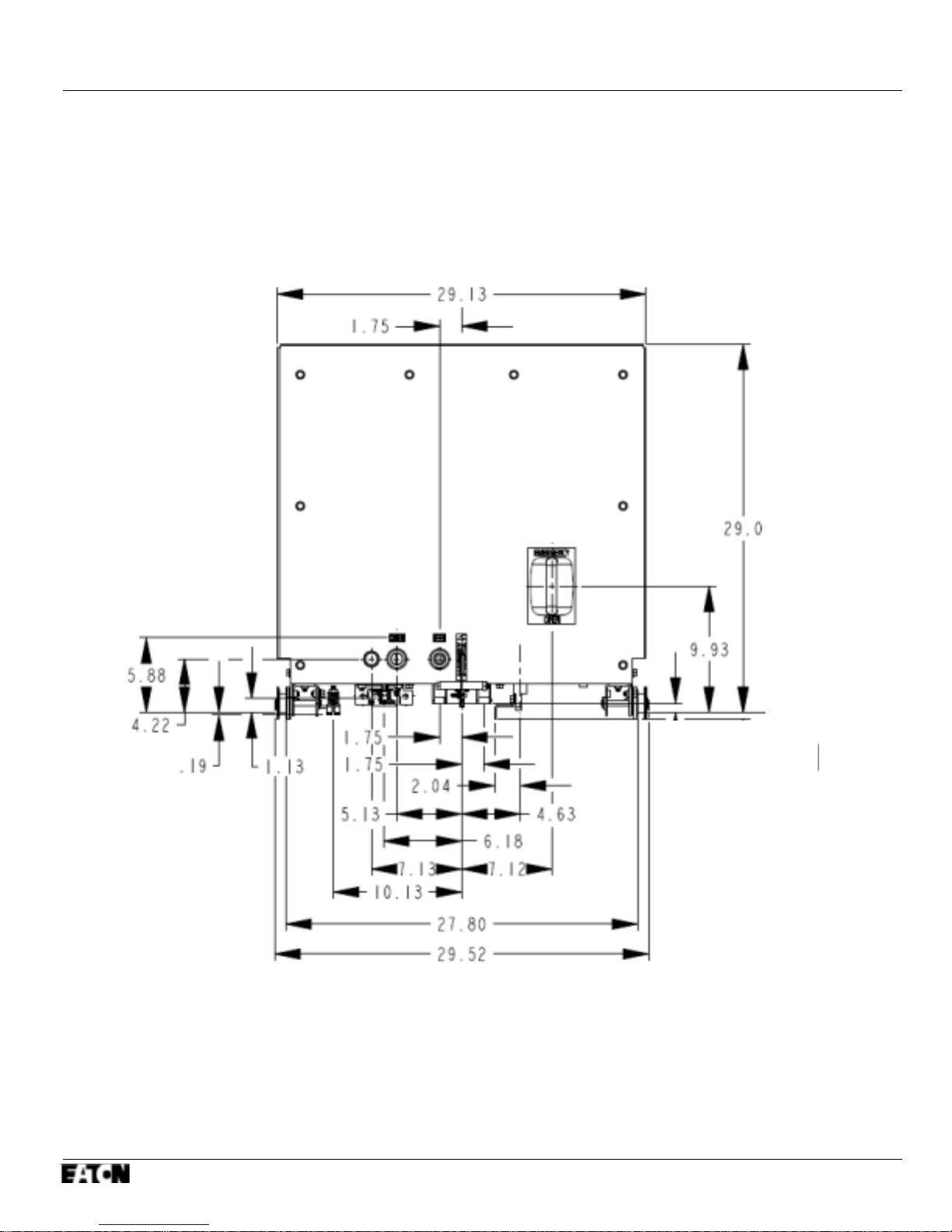
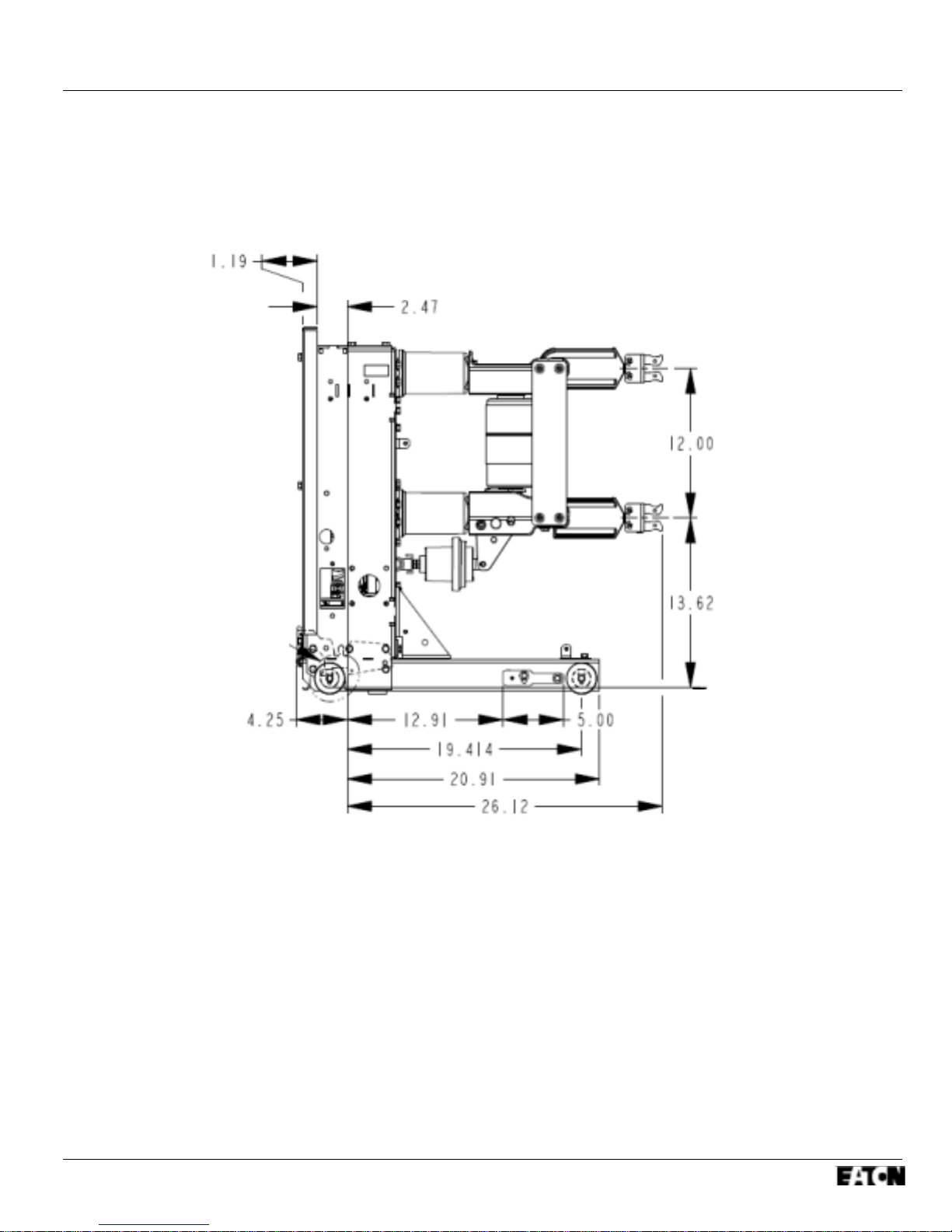
OUTLINES AND DIMENSIONS1-4
Figure 1-1 Type VCP-WL Circuit Breaker Outlines and Dimensions
Effective Mar 2018
Front View
IB13 1021EN P ag e v
SECTION 2: SAFE PRACTICES
Effective Mar 2018
Side View
2-1 RECOMMENDATIONS
Type VCP-WL Vacuum Circuit Breaker Elements are
equipped with high speed, high energy operating
mechanisms, and are designed with several built-in inter-

Pag e vi IB13 1021EN
locks and safety features to provide safe and proper
operating sequences.
WARNING
TO PROTECT THE PERSONNEL ASSOCIATED WITH
INSTALLATION, OPERATION, AND MAINTENANCE OF
THESE CIRCUIT BREAKER ELEMENTS, THE
FOLLOWING PRACTICES MUST BE FOLLOWED:
Only qualified personnel, as defined in the local
electrical code, who are familiar with the installation and
maintenance of medium voltage circuits and equipment,
should be permitted to work on these circuit breaker
elements.
Read these instructions carefully before attempting
any installation, operation or maintenance of these
breakers.
Always remove the breakers from the enclosure before
performing any maintenance. Failure to do so could
result in electrical shock leading to death, severe
personal injury or property damage.
tripping. Carelessness could cause the circuit breaker to
fall from the rails resulting in personal injury to those in the
area.
Do not work on a closed breaker or a breaker with
capacitor bank charged. The capacitor bank should be
discharged and the main contacts open before working
on the breaker. The capacitor bank will discharge after
control power is removed. Failure to do so could result in
severe injury or death.
Do not use a circuit breaker by itself as the sole means of
isolating a high voltage circuit. Remove the breaker to the
DISCONNECT position and follow good lockout and
tagging rules, as well as all applicable codes, regulations
and work rules.
Do not leave the breaker in an intermediate position in
the cell. Always have the breaker either in the TEST or
CONNECTED position. Failure to do so could result in a
flash over and possible death, personal injury or property
damage.
Breakers are equipped with safety interlocks. Do not
defeat them. This may result in death, bodily injury or
equipment damage.
BE EXTREMELY CAREFUL while the circuit breaker is
on the extension rails. Use provided rail clamps to firmly
hold the circuit breaker on the extension rails while
performing such activities as charging, closing and
SECTION 3: RECEIVING, HANDLING AND
STORAGE
Effective Mar 2018
IB13 1021EN P ag e vii
3-1 GENERAL
Type VCP-WL Vacuum Circuit Breaker Elements are
subjected to complete factory production tests and
inspection before being packed. They are shipped in
packages designed to provide maximum protection to the
equipment during shipment and storage and at the same
time to provide convenient handling.
3-2 RECEIVING
If the circuit breaker element is not to be used immediately
but is to be placed in storage; maximum protection can be
obtained by keeping it packed as shipped.
Upon receipt of the equipment, inspect the containers for
any signs of damage or rough handling. Open the
containers carefully to avoid any damage to the con-tents.
Use a nail puller rather than a crow bar when required.
When opening the containers, be careful to save any loose
items or hardware that may be otherwise discarded with
the packing material. Check the contents of each package
against the packing list.
Examine the circuit breaker element for any signs of
shipping damage such as broken, missing or loose
hardware, damaged or deformed insulation and other
components. File claims immediately with the carrier if
damage or loss is detected and notify the nearest Eaton
Office.
breaker element side openings with the lifting hole toward
the interrupters. Once the lifting yoke is securely seated in
the holes, the breaker element can be carefully lifted and
moved.
3-4 STORAGE
If the circuit breaker element is to be placed in storage,
maximum protection can be obtained by keeping it packed
as shipped. Before placing it in storage, checks should be
made to make sure that the breaker element is free from
shipping damage and is in satisfactory operating condition.
The circuit breaker element is shipped with its contacts
open and capacitor bank discharged. The indicators on the
front panel should confirm this.
Outdoor storage of the breaker element is NOT
recommended. If unavoidable, the outdoor location must
be well drained and a temporary shelter from sun, rain,
snow, corrosive fumes, dirt, falling objects and excessive
moisture must be provided. Containers should be arranged
to permit free circulation of air on all sides and temporary
heaters should be used to minimize condensation.
Moisture can cause rusting of metal parts and deterioration
of high voltage insulation. A heat level of approximately
400 watts for each 100 cubic feet of volume is
recommended with the heaters distributed uniformly
throughout the structure near the floor.
Indoor storage should be in a building with sufficient heat
and air circulation to prevent condensation. If the building is
not heated, the same general rule for heat as for outdoor
storage should be applied.
3-3 HANDLING
CAUTION
DO NOT USE ANY LIFTING DEVICE AS A PLATFORM
FOR PERFORMING MAINTENANCE, REPAIR OR
ADJUSTMENT OF THE BREAKER OR FOR OPENING,
CLOSING THE CONTACTS OR CHARGING THE
SPRINGS. THE CIRCUIT BREAKER ELEMENT MAY
SLIP OR FALL CAUSING SEVERE PERSONAL INJURY.
ALWAYS PERFORM MAINTENANCE, REPAIR AND
ADJUSTMENTS ON A SOLID WORK SURFACE
CAPABLE OF SUPPORTING THE BREAKER
ELEMENT.
When a breaker element is ready for installation, a lifting
yoke in conjunction with an overhead lifter or portable floor
lifter can be used to move a breaker element. When a
breaker element is to be lifted, position the lifting yoke over
the breaker element and insert the lifter tabs into the
Effective Mar 2018
3-5 TOOLS AND ACCESSORIES
Tools and accessories, both standard and optional are
available for use with the circuit breaker element
(Figure 3-1).

Pag e viii IB13 1021EN
Amperes Lbs. (kg)
50VCP-WL25 1200 350
75VCP-WL25 1200 350
150VCP-WL25 1200 350
Spin-Free Levering-In Crank: Used to crank breaker
between TEST and CONNECTED positions (Style
701B601G11).
Extension Rails: Permits breaker to be withdrawn from its
compartment (Style 7813C41G03 for VCP-WL).
Rail Clamps: Used to secure breaker to extension rails
(Style 6511C83G11 for VCP-WL).
Lifting Yoke: Used to lift breaker (Style 691C607G11 for
VCP-WL).
Drawout Ramp: Used to insert or withdraw breaker from
lower compartment without portable lifter (Style
1C14163G02 for VCP-WL).
Table 3-1 VCP-WL ANSI Rated Breaker Weights
Rating
Does not include shipping carton
①
Portable Lifter: Used to lift breaker to or from extended
rails (Style 1C14504H01).
Docking Transport Dolly: Used to insert or withdraw
breaker from lower compartment without portable lifter or
move breaker from one location to another (Style
6510C71G11 for VCP-WL).
Electrical Levering-In Device: Used to electrically move
breaker between TEST and CONNECTED positions (Style
1A30257G01).
Test Jumper: Used to operate breaker electrically while
breaker is on extension rails or transport dolly (Style
6526C23G11 for VCP-WL).
Test Cabinet: Used to provide power to operate breaker
outside its compartment (Styles 8346A28G21 – G23 for
VCP-WL depending on voltage requirements).
3-6 TYPE VCP-WL VACUUM CIRCUIT BREAKER
ELEMENT WEIGHTS (TABLE 3.1)
Effective Mar 2018
 Loading...