

Eaton 50 VCP-T16, 50 VCP-T20, 50 VCP-T25, 50 VCP-TR20, 50 VCP-T32 Instructions For The Use
...
Instructions for the Use, Operation and Maintenance of
Types VCP-T and VCP-TR Vacuum Circuit Breakers
IB131016EN Effective November 2017
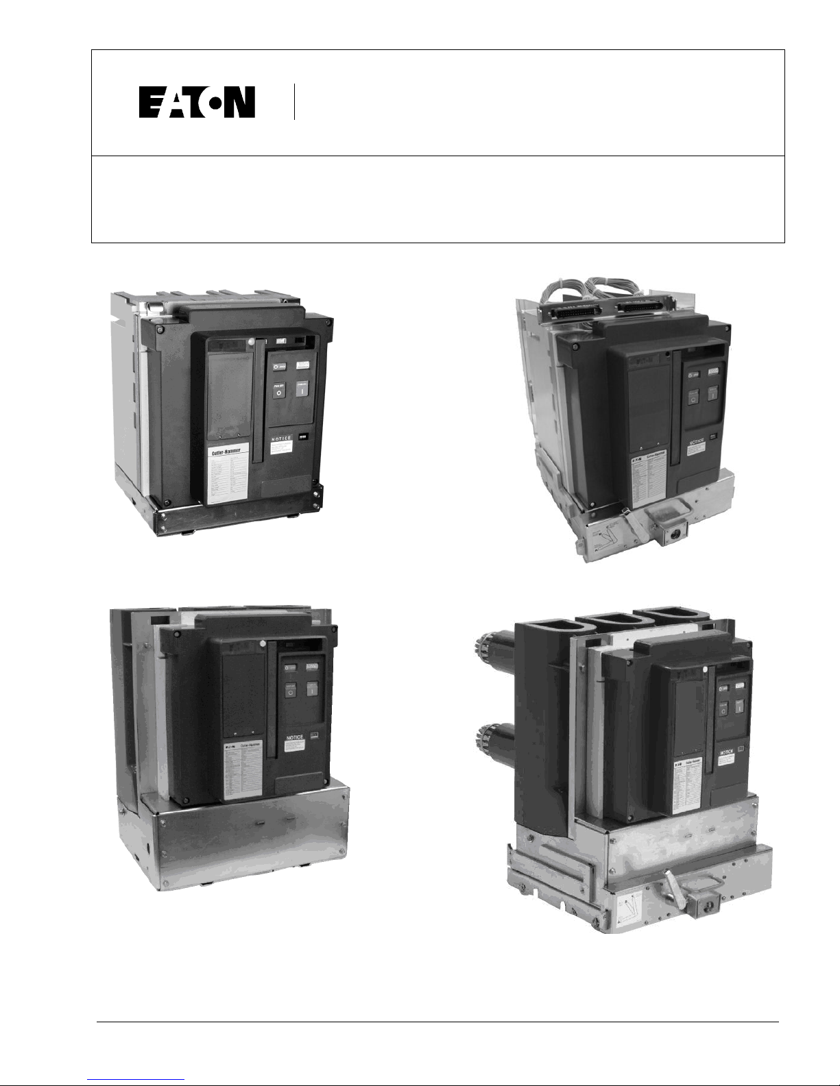
VCP-TR Fixed (up to 25kA)
VCP-TR Fixed (up to 40kA)
VCP-T Drawout (up to 25kA)
VCP-T Drawout (up to 40kA)
IB131016EN For more information visit: www.Eaton.com


Instruction Book
Effective: November 2017 Page iii
WARNING
IMPROPERLY INSTALLING OR MAINTAINING
THESE PRODUCTS CAN RESULT IN DEATH,
SERIOUS PERSONAL INJURY, OR PROPERTY
DAMAGE.
READ AND UNDERSTAND THESE INSTRUCTIONS
BEFORE ATTEMPTING ANY UNPACKING,
ASSEMBLY, OPERATION OR MAINTENANCE OF
THE CIRCUIT BREAKERS.
INSTALLATION OR MAINTENANCE SHOULD BE
ATTEMPTED ONLY BY QUALIFIED PERSONNEL.
THIS INSTRUCTION BOOK SHOULD NOT BE
CONSIDERED ALL INCLUSIVE REGARDING
INSTALLATION OR MAINTENANCE
PROCEDURES. IF FURTHER INFORMATION IS
REQUIRED, YOU SHOULD CONTACT EATON
Eaton Corporation
Moon Township, PA. 15108
WARNING
THE CIRCUIT BREAKER ELEMENTS DESCRIBED
IN THIS BOOK ARE DESIGNED AND TESTED TO
OPERATE WITHIN THEIR NAMEPLATE RATINGS.
OPERATION OUTSIDE OF THESE RATINGS MAY
CAUSE THE EQUIPMENT TO FAIL, RESULTING IN
DEATH, BODILY INJURY AND PROPERTY
DAMAGE.
ALL SAFETY CODES, SAFETY STANDARDS
AND/OR REGULATIONS AS THEY MAY BE
APPLIED TO THIS TYPE OF EQUIPMENT MUST BE
STRICTLY ADHERED TO.
SERIOUS INJURY, INCLUDING DEATH, CAN
RESULT FROM FAILURE TO FOLLOW THE
PROCEDURES OUTLINED IN THIS MANUAL.
THESE CIRCUIT BREA K ER E LE M EN TS A RE S OL D
PURSUANT TO A NON-STANDARD PURCHASING
AGREEM ENT WHICH LIMITS THE LIABILITY OF
THE MANUFACTURER.
All possible contingencies which may arise during installation, operation or maintenance, and all details and
variations of this equipment do no purport to be covered by these instructions. If further information is
desired by purchaser regarding his particular installation, operation or maintenance of particular equipment,
contact an Eaton representative .
IB131016EN For more information visit: www.Eaton.com

Instruction Book
Page iv Effective: November 2017
TABLE OF CONTENTS
SECTION 1: INTRODUCTION
1-1 VCP-T and VCP-TR Vacuum Circuit Breaker Ratings .................................................................................................................................. 1
1-2 Types VCP-T and VCP-TR Outlines and Dimensions ................................................................................................................................. 4
SECTION 2: SAFE PRACTICES
SECTION 3: RECEIVING, HANDLING AND STORAGE
3-1 Receiving ..................................................................................................................................................................................................... 12
3-2 Handling ....................................................................................................................................................................................................... 12
3-2.1 Unpacking .................................................................................................................................................................................. 12
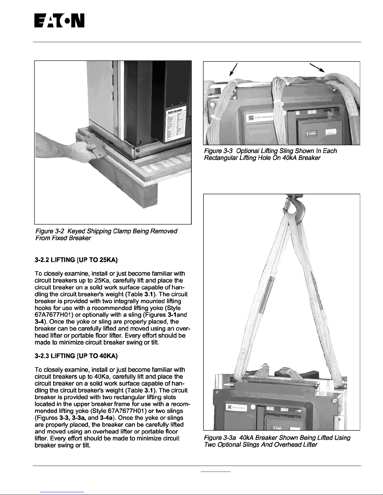
3-2.2 Lifting (up to 25kA) ..................................................................................................................................................................... 13
3-2.3 Lifting (up to 40kA) ..................................................................................................................................................................... 13
3-3 Storage ....................................................................................................................................................................................................... 14
3-4 Typical Breaker and Cassette Weights ...................................................................................................................................................... 15
SECTION 4: INSTALLATION AND WIRING
4-1 Initial Inspection ......................................................................................................................................................................................... 22
4-2 Electrical Clearances ................................................................................................................................................................................. 22
4-3 Interphase Barriers ...................................................................................................................................................................................... 22
4-4 Front Cover ................................................................................................................................................................................................ 22
4-5 Installing Fixed Circuit Breaker .................................................................................................................................................................. 22
4-5.1 Fixed Mechanical Interfaces ...................................................................................................................................................... 22
4-5.2 Fixed Electrical Interfaces ......................................................................................................................................................... 22
4-6 Installing Drawout Circuit Breaker ............................................................................................................................................................... 23
4-6.1 Drawout Mechanical Interfaces ................................................................................................................................................. 23
4-6.2 Circuit Breaker Positioning ........................................................................................................................................................ 24
4-6.3 Drawout Electrical Interfaces ..................................................................................................................................................... 26
4-6.4 Levering Circuit Breaker ............................................................................................................................................................ 28
SECTION 5: DESCRIPTION AND OPERATION
5-1 Introduction ................................................................................................................................................................................................ 31
5-2 Vacuum Interrupter Assembly .................................................................................................................................................................... 31
5-2.1 Contact Erosion Indicator (up to 25kA) ...................................................................................................................................... 34
5-2.2 Contact Wipe and Stroke (up to 25kA) ...................................................................................................................................... 34
5-2.3 Contact Wipe and Erosion (up to 40kA) ..................................................................................................................................... 34
5-3 Stored Energy Mechanism ......................................................................................................................................................................... 35
5-3.1 Manual Operation ...................................................................................................................................................................... 35
5-3.2 Electrical Operation ................................................................................................................................................................... 36
5-3.3 Trip Free Operation ................................................................................................................................................................... 36
5-3.4 Anti-Pump Feature .................................................................................................................................................................... 36
5-3.5 Latch Check Switch ................................................................................................................................................................... 36
5-3.6 Mechanical Interlocks ................................................................................................................................................................ 36
5-4 Connection Diagrams ................................................................................................................................................................................... 37
5-4.1 Timing ......................................................................................................................................................................................... 37
5-4.2 Sensors ........................................................................................................................................................................................ 37
5-5.4 Trip Actuator ............................................................................................................................................................................... 37
5-6 Accessory Devices Secondary Connections ................................................................................................................................................ 43
5-5 Electronic Tripping System .......................................................................................................................................................................... 43
5-5.1 Microprocessor-Based Trip Unit .................................................................................................................................................. 44
5-5.2 Rating Plug ................................................................................................................................................................................. 44
5-5.3 Current ......................................................................................................................................................................................... 45
5-6.1 Plug-in Electrical Accessories...........................................................................................
5-6.2 Internal Electrical Accessories ..................................................................................................................................................... 47
5-6.3 Mechanical Accessories ............................................................................................................................................................. 49
SECTION 6: INSPECTION AND MAINTENANCE
6-1 Introduction .................................................................................................................................................................................................. 50
6-2 Frequency of Inspection and Maintenance ................................................................................................................................................. 50
........................................................... 46
Page
For more information visit: www.Eaton.com IB131016EN

Instruction Book
Effective: November 2017 Page v
6-3 Vacuum Interrupter Integrity Test ................................................................................................................................................................. 49
6-4 Contact Erosion (up to 25kA) ....................................................................................................................................................................... 51
6-5 Contact Wipe (up to 25kA) ........................................................................................................................................................................... 51
6-6 Insulation ...................................................................................................................................................................................................... 54
6-7 Insulation Integrity Check .............................................................................................................................................................................. 54
6-8 Primary Circuit Resistance Check ............................................................................................................................................................... 54
6-9 Mechanism Check ....................................................................................................................................................................................... 54
6-10 Lubrication ................................................................................................................................................................................................... 54
6-11 Troubleshooting ........................................................................................................................................................................................... 54
6-14 End of Life Procedures…………………………………………………………………………………………………………………………………..59
6-15 Failure Reporting………………………………………………………………………………………………………………………………………….59
SECTION 7: RENEWAL PARTS
7-1 General ........................................................................................................................................................................................................ 59
7-2 Ordering Instructions ..................................................................................................................................................................................... 59
7-3 Mechanism and Related Parts ..................................................................................................................................................................... 60
7-4 Current Path .................................................................................................................................................................................................. 61
7-5 Electrical Attachments .................................................................................................................................................................................. 62
7-6 Other Breaker Related Parts ......................................................................................................................................................................... 65
7-7 Trip Unit and Related Parts ........................................................................................................................................................................... 68
LIST OF FIGURES
1-1 VCP-TR Fixed Breaker Outlines (except 25kA, 2000/2500A and all 31.5/40kA) ................................................................................... 4
1-2 VCP-T Drawout Breaker Outlines (except 25kA, 2000A and all 31.5/40kA) ......................................................................................... 5
1-3 VCP-T Breaker Cassette Outlines (except 25kA, 2000A and all 31.5/40kA) ......................................................................................... 6
1-4 VCP-TR Fixed Breaker Outlines (25kA, 2000/2500A and all 31.5/40kA) .............................................................................................. 7
1-5 VCP-T Drawout Breaker Outlines (25kA, 2000A and all 31.5/40kA) ..................................................................................................... 8
1-6 VCP-T Breaker Cassette Outlines (25kA, 2000A and all 31.5/40kA) .................................................................................................... 9
-------------------------------------------------------------------------------------------------------------------------------------------------------------------------------
3-1 Fixed Breaker Shown Mounted on Pallet ............................................................................................................................................. 12
3-2 Keyed Shipping Clamp Being Removed from Fixed Breaker .............................................................................................................. 13
3-3 Optional Lifting Sling Shown on 40kA Breaker .................................................................................................................................... 13
3-3a 40kA Breaker Shown Being Lifted with Optional Lifting Slings ............................................................................................................ 13
3-4 Preferred Lifting Method Using Lifting Yoke To Lift 25kA Breaker ....................................................................................................... 14
3-4a Preferred Lifting Method Using Lifting Yoke To Lift 40kA Breaker ....................................................................................................... 14
3-5 Front and Rear Views All VCP-TR Fixed (except 25kA, 2000/2500A and all 31.5/40kA) .................................................................... 16
3-6 Front and Rear Views All VCP-T Drawout (except 25kA, 2000A and all 31.5/40kA) .......................................................................... 17
3-7 Front and Rear Views Drawout Cassette (except 25kA, 2000A and all 31.5/40kA) ............................................................................ 18
3-8 Front and Rear Views VCP-T Drawout Breaker (25kA, 2000A and all 31.5/40kA) .............................................................................. 19
3-9 Front and Rear Views Drawout Cassette (25kA, 2000A and all 31.5/40kA) ......................................................................................... 20
3-10 Typical VCP-T Front Cover ................................................................................................................................................................... 21
4-1 Typical Fixed Non-Automatic VCP-TR 15KV Circuit Breaker ............................................................................................................... 23
4-2 Bottom View of VCP-TR Circuit Breaker showing Mounting Holes ..................................................................................................... 23
4-3 Cassette Rejection Interlock Pin Positioning ....................................................................................................................................... 24
4-4 Position Circuit Breaker with Lifter on Removable Extension Rails ..................................................................................................... 25
4-5 Breaker Shoot Bolts Against Cassette .................................................................................................................................................. 25
4-6 Shoot Bolt Handle in Up (Locked) Position ........................................................................................................................................... 25
4-7 Shoot Bolt Handle Shown in Position “C” - Shoot Bolts Protrude Fully from Cradle ............................................................................ 26
4-8 Shoot Bolt Handle Shown in Position “B” - Shoot Bolts Protrude Partially from Cradle ....................................................................... 26
4-9 Shoot Bolt Handle Shown in Position “A” - Shoot Bolts Retracted Fully Inside Cradle ........................................................................ 26
4-10 Circuit Breaker Umbilical Cord Shown Connected to Breaker Prior to Breaker Insertion .................................................................... 27
4-11 Secondary Connector Viewed from Rear of Breaker ............................................................................................................................ 27
4-12 Cassette Secondary Connector and Interlock Lever ........................................................................
4-13 Drawout Cassette with Primary Safety Shutters Open Showing Fixed Primary Stabs ........................................................................ 28
4-14 Circuit Breaker Shown in Levered Out (DISCONNECT) Position - Correct for Breaker Positioning ................................................... 28
4-15 Circuit Breaker Shown in Levered In (CONNECT) Position - Incorrect for Breaker Positioning........................................................... 28
................................................... 27
IB131016EN For more information visit: www.Eaton.com

Instruction Book
Page vi Effective: November 2017
4-16 Cradle Mounted Levering Mechanism ..................................................................................................................................................... 29
4-17 Levering Circuit Breaker .......................................................................................................................................................................... 29
4-18 Circuit Breaker Connected as Indicated by Fully Connected Position Label ........................................................................................... 29
4-19 Circuit Breaker Shown in CONNECT Position with Secondary Connections Made ................................................................................ 30
4-20 Primary Safety Shutters Shown in Open Position with Fixed Primary Stabs Exposed ............................................................................. 30
4-21 Padlocking Device on Side of Cassette ................................................................................................................................................... 30
5-1 Rigid Frame Construction ........................................................................................................................................................................ 31
5-2 VCP-TR Fixed Non-automatic Circuit Breaker (Front Cover Removed) .................................................................................................. 32
5-3 VCP-T Drawout Circuit Breaker (Front Cover Removed) ........................................................................................................................ 33
5-4 Typical Fixed 50 VCP-TR Interrupter Assembly ...................................................................................................................................... 34
5-5 Typical Drawout 150 VCP-T Interrupter Assembly .................................................................................................................................. 34
5-6 Breaker Closing Springs Being Manually Charged ................................................................................................................................... 35
5-7 Motor Operator Shown Installed .............................................................................................................................................................. 36
5-8 Typical Cover Mounted Key Interlock ...................................................................................................................................................... 36
5-9 Typical Mechanical Cable Interlock ......................................................................................................................................................... 37
5-10 VCP-T and VCP-TR Non Trip Unit Connection Diagram ......................................................................................................................... 38
5-11 VCP-T and VCP-TR with 520V Trip Unit Connection Diagram ................................................................................................................. 39
5-12 VCP-T and VCP-TR with 1150V Trip Unit Connection Diagram ............................................................................................................... 40
5-12A VCP-T and VCP-TR with 520MCV Trip Unit Connection Diagram ........................................................................................................... 41
5-13 VCP-T Drawout Umbilical Cord and Connector Wiring Diagram ............................................................................................................. 42
5-14 Secondary Connectors Shown Mounted without Secondary Protective Hood in Place .......................................................................... 37
5-15 Top View Secondary Connectors ............................................................................................................................................................ 43
5-16 Secondary Male Connector with Female Pins ......................................................................................................................................... 43
5-17 Optional Terminal Block ........................................................................................................................................................................... 43
5-18 AMP Secondary Wiring Removal Tool (AMP#305183) ........................................................................................................................... 43
5-19 Digitrip RMS 1 150Vi Programmable Trip Unit Installed in VCP-T Circuit Breaker................................................................................... 44
5-20 Hand Held Tester ...................................................................................................................................................................................... 44
5-21 Through-The-Window Electrical Accessories .......................................................................................................................................... 46
5-22 Shunt Trip Device .................................................................................................................................................................................... 46
5-23 Spring Release Device ............................................................................................................................................................................ 46
5-24 Undervoltage Release Device ................................................................................................................................................................. 47
5-25 Rugged Motor Operator ............................................................................................................................................................................ 48
5-26 Auxiliary Switch ........................................................................................................................................................................................ 48
5-27 Pushbutton Cover Mounted ..................................................................................................................................................................... 49
5-28 Door Escutcheon and Gasket .................................................................................................................................................................. 49
6-1 Contact Erosion Mark Visible on Stem .................................................................................................................................................... 53
6-2 Contact Wipe Inspection Area ................................................................................................................................................................. 53
6-3 Satisfactory Contact Wipe Condition with Breaker Closed ...................................................................................................................... 53
6-4 Unsatisfactory Contact Wipe Condition with Breaker Closed .................................................................................................................. 53
6-5 Contact Wipe Measurement 40kA Breaker ............................................................................................................................................... 54
6-6 40kA Breaker Contact Wipe Graphic ....................................................................................................................................................... 54
6-7 Circuit Breaker Lubrication ....................................................................................................................................................................... 58
6-8 Drawout Cassette Lubrication .................................................................................................................................................................. 59
LIST OF TABLES
Table Title Page
1.1 VCP-T and VCP-TR Ratings ...................................................................................................................................................................... 2
3.1 Circuit Breaker and Cassette Weights ..................................................................................................................................................... 15
4.1 Cassette Rejection Interlock Pin Locations ............................................................................................................................................... 23
5.1 Digitrip Trip Units ..................................................................................................................................................................................... 44
5.2 Current Sensors and Matching Rating Plugs ........................................................................................................................................... 45
5.3 Shunt Trip Ratings ................................................................................................................................................................................... 47
5.4 Spring Release Ratings ........................................................................................................................................................................... 47
5.5 Undervoltage Release Ratings ................................................................................................................................................................ 47
5.6 Motor Operator Ratings ........................................................................................................................................................................... 48
5.7 Auxiliary Switch Contacts Interrupting Capacities ..................................................................................................................................... 48
6.1 Inspection and Maintenance Procedures ................................................................................................................................................. 51
6.2 Test Voltage .............................................................................................................................................................................................. 52
6.3 Typical Resistance Measurements .......................................................................................................................................................... 55
6.4 Troubleshooting Guide .............................................................................................................................................................................. 56
For more information visit: www.Eaton.com IB131016EN

Instruction Book
Effective: November 2017 Page 1
SECTION 1: INTRODUCTION
The purpose of this book is to provide instructions for
unpacking, storage, use operation and maintenance
of VCP-T drawout type and VCP-TR fixed type
Vacuum Circuit Breakers. VCP-T and VCP-TR are
compact vacuum interrupting elements designed for
applications such as: mine power centers, portable
power stations, fixed breaker or drawout switchgear
and portable generators, all without compromising
metal clad expectations. VCP-T and VCP-TR
breakers were specifically designed to provide proven
reliable performance in a small package. The circuit
breakers are available in voltage classes of 4.76, 8.25
and 15.0 kV. They are tested in accordance with ANSI
C37.04 and C37.09 (Table 1.1).
1-1 VCP-T and VCP-TR Vacuum Breaker Ratings
Refer to Tables 1.1 and 1.2 on pages 2 and 3.
The circuit breaker's nameplate provides complete
rating information. Reliable control and protection for
medium voltage equipment and circuits are achieved
through the use of VCP-T and VCP-TR Vacuum
Breakers.
WARNING
SATISFACTORY PERFORMANCE OF THESE
BREAKERS IS CONTINGENT UPON PROPER
APPLICATION, CORRECT INSTALLATION AND
ADEQUATE MAINTENANCE. THIS INSTRUCTION
BOOK MUST BE CAREFULLY READ AND
FOLLOWED IN ORDER TO OBTAIN OPTIMUM
PERFORMANCE FOR LONG USEFUL LIFE OF THE
CIRCUIT BREAKERS.
VCP-T and VCP-TR CIRCUIT BREAKERS ARE
PROTECTIVE DEVICES, AS SUCH, THEY ARE
MAXIMUM RATED DEVICES. THEREFORE, THEY
SHOULD NOT UNDER ANY CIRCUMSTANCES BE
APPLIED OUTSIDE THEIR NAMEPLATE RATINGS.
IB131016EN For more information visit: www.Eaton.com
Instruction Book
Effective: November 2017 Page 2
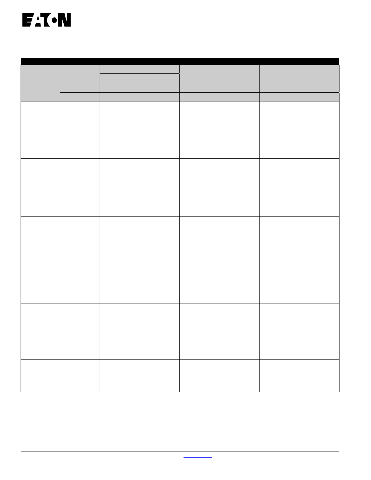
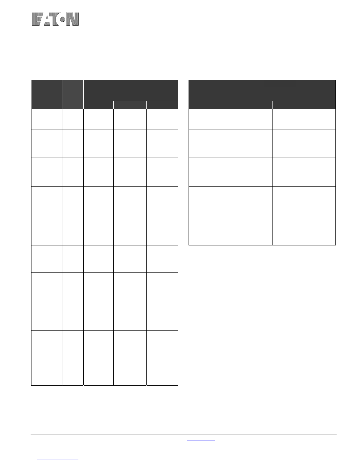
Table 1.1 VCP-T and VCP-TR Ratings (ANSI C37. 04 and C37. 09) (continued on next page)
Identification Rated Values
Circuit
Breaker
Type
Insulation Level
Voltage
Class
Power
Frequency
Impulse
Withstand
kV rms kV rms kV Peak
Continuous
Current
Amperes
Short Circuit `
Breaking
Current
kA rms
Short Circuit
Making
Current
Mechanical
Endurance
C - O
kA Peak Operations
50 VCP-T16
and
50 VCP-TR16
50 VCP-T20
and
50 VCP-TR20
50 VCP-T25
and
50 VCP-TR25
50 VCP-T32
and
50 VCP-TR32
50 VCP-T40
and
50 VCP-TR40
75 VCP-T16
and
75 VCP-TR16
75 VCP-T20
and
75 VCP-TR20
4.76 19 60
4.76 19 60
4.76 19 60
4.76 19 60
4.76 19 60
8.25 20
8.25 20
60
60
600
1200
1600
600
1200
1 600
600
1200
1600
2000
2500
600
1200
2000
2500
600
1200
2000
2500
600
1200
1600
600
1200
1600
16 42
20 52
25 65
31.5 82
40 104
16 42
20 52
10000
10000
10000
10000
10000
10000
10000
10000
10000
10000
10000
10000
10000
10000
10000
10000
10000
10000
10000
10000
10000
10000
10000
10000
10000
75 VCP-T25
and
75 VCP-TR25
75 VCP-T32
and
75 VCP-TR32
75 VCP-T40
and
75 VCP-TR40
Use 15kV Breaker and Cassette when 95kV Impulse Withstand required Also 2 Second Short Time Current Rating
1600A and 2500A available as fixed VCP-TR circuit breaker only
8.25 20
8.25 20
8.25 20
For more information visit: www.Eaton.com IB131016EN
600
60
60
60
1200
1600
2000
2500
600
1200
2000
2500
600
6040
1200
2000
2500
25 65
31.5 82
40 104
10000
10000
10000
10000
10000
10000
10000
10000
10000
10000
10000
10000
10000
Instruction Book
Effective: November 2017 Page 3
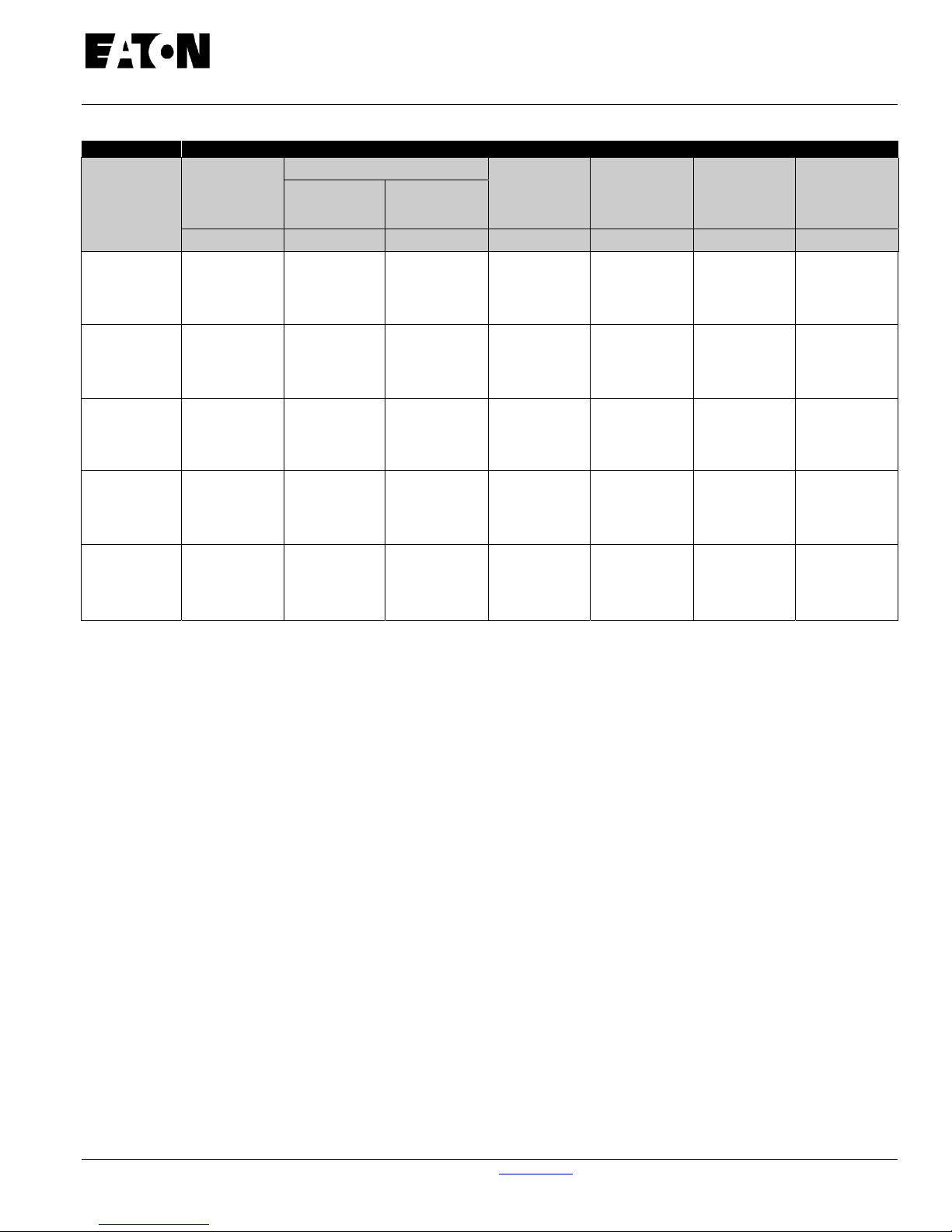
Table 1.1 VCP-T and VCP-TR Ratings (ANSI C37. 04 and C37. 09) (continued from previous page)
Identification Rated Values
Circuit
Breaker
Type
Insulation Level
Voltage
Class
Power
Frequency
Impulse
Withstand
kV rms kV rms kV Peak
Continuous
Current
Amperes
Short Circuit `
Breaking
Current
kA rms
Short Circuit
Making
Current
Mechanical
Endurance
C - O
kA Peak Operations
150 VCP-T16
and
150 VCP-TR16
150 VCP-T20
and
150 VCP-TR20
150 VCP-T25
and
150 VCP-TR25
150 VCP-T32
and
150 VCP-TR32
150 VCP-T40
and
150 VCP-TR40
Use 15kV Breaker and Cassette when 95kV Impulse Withstand required Also 2 Second Short Time Current Rating
1600A and 2500A available as fixed VCP-TR circuit breaker only
Tested for capacitor switching capabilities. “General Purpose” to ANSI C37: Cable charging = 25A. "Definite Purpose" to ANSI C37:
Back-to-back equals 250A and 1000A. Ratings of 250 and 1000A cover capacitor bank applications from 75 to 1000A.
Inrush current and frequency rating = 18 kApk at 2.4 kHz.
15 36 95
15 36 95
15 36 95
15 36 95
15 36 95
600
1200
1600
600
1200
1600
600
1200
1600
2000
2500
600
1200
2000
2500
600
1200
2000
2500
16 42
20 52
25 65
31.5 82
40 104
10000
10000
10000
10000
10000
10000
10000
10000
10000
10000
10000
10000
10000
10000
10000
10000
10000
10000
IB131016EN For more information visit: www.Eaton.com
Instruction Book
Effective: November 2017 Page 4
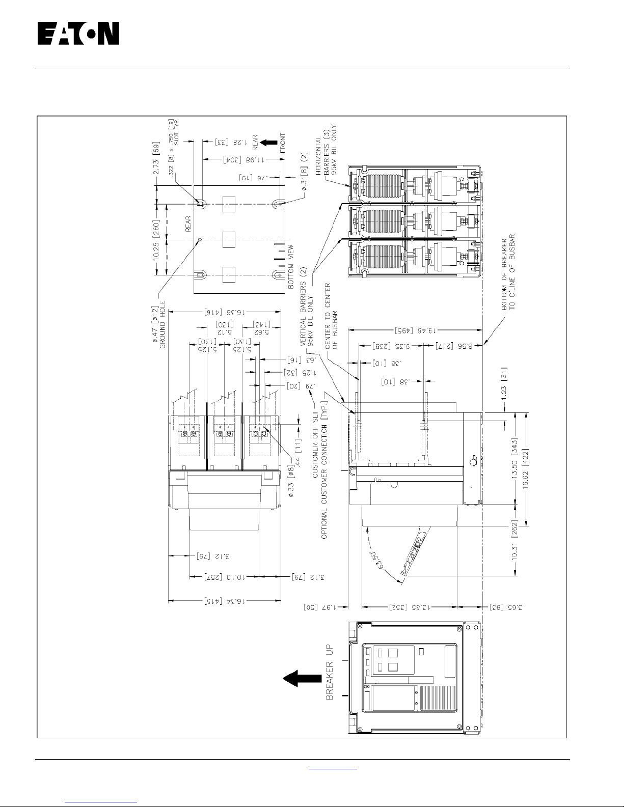
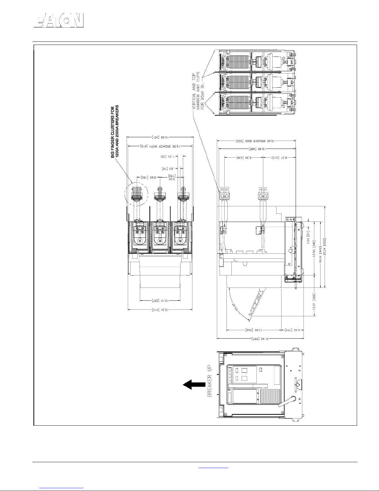
1-2 Types VCP-T and VCP-TR Outlines and Dimensions (Circuit Breakers and Drawout Cassettes)
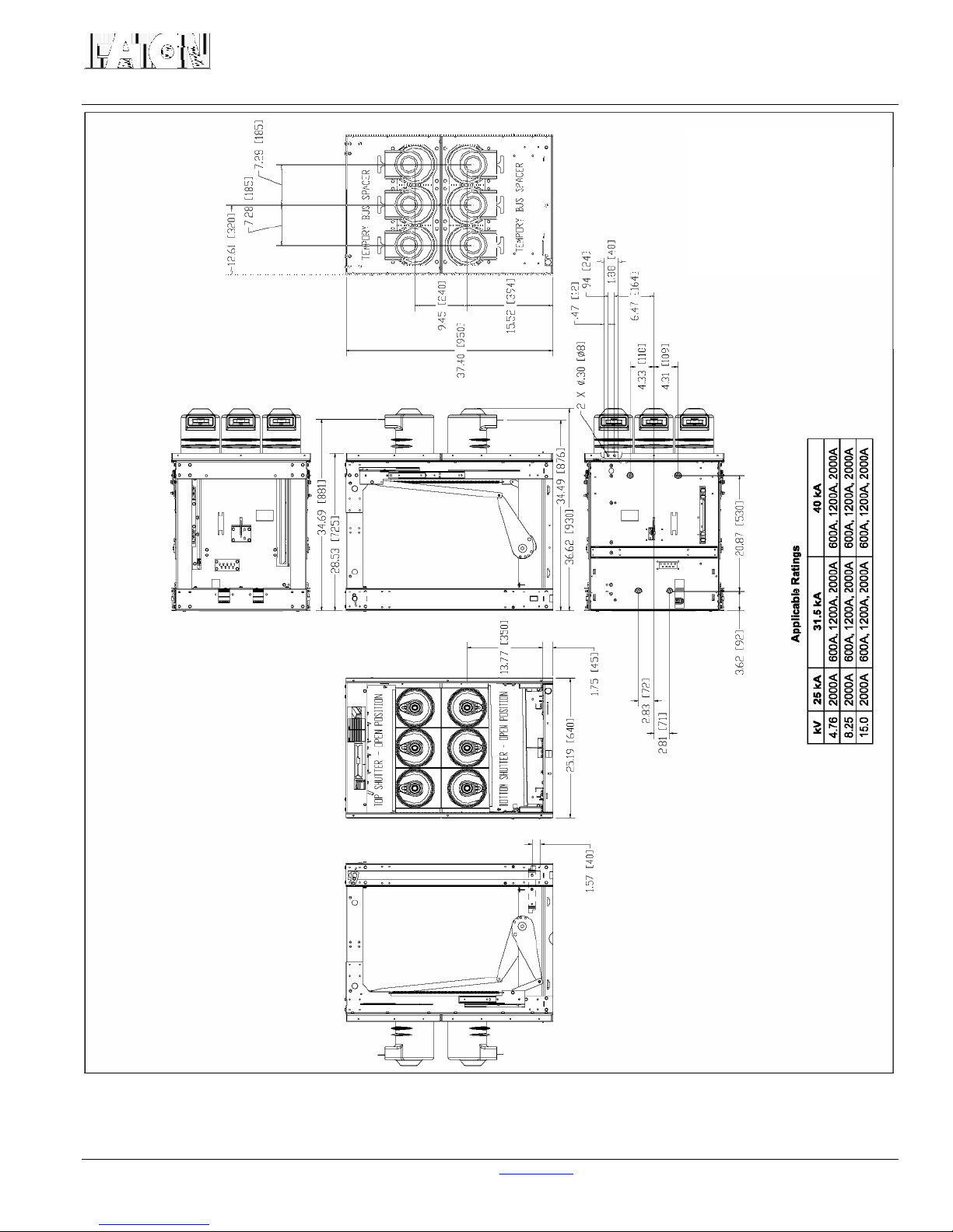
Figure 1-1 VCP-TR Fixed Breaker Outlines in inch es [mm] (e xcept 25kA, 2000/2500A and all 31.5/40kA)
For more information visit: www.Eaton.com IB131016EN
Instruction Book
Effective: November 2017 Page 5
Figure 1-2 VCP-T Drawout Breaker Outlines in inches [mm] (except 25kA, 2000A and all 31.5/40kA)
IB131016EN For more information visit: www.Eaton.com
Instruction Book
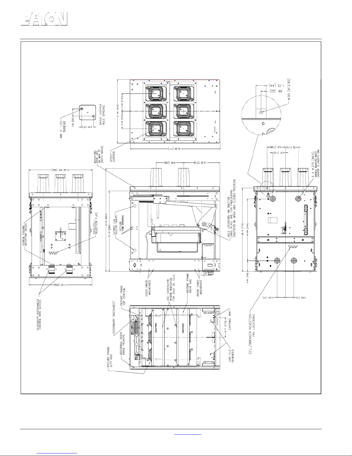
Effective: November 2017 Page 6
Figure 1-3 VCP-T Breaker Cassette Outlines in inches [mm] (except 25kA, 2000A and all 31.5/40kA)
For more information visit: www.Eaton.com IB131016EN
Instruction Book
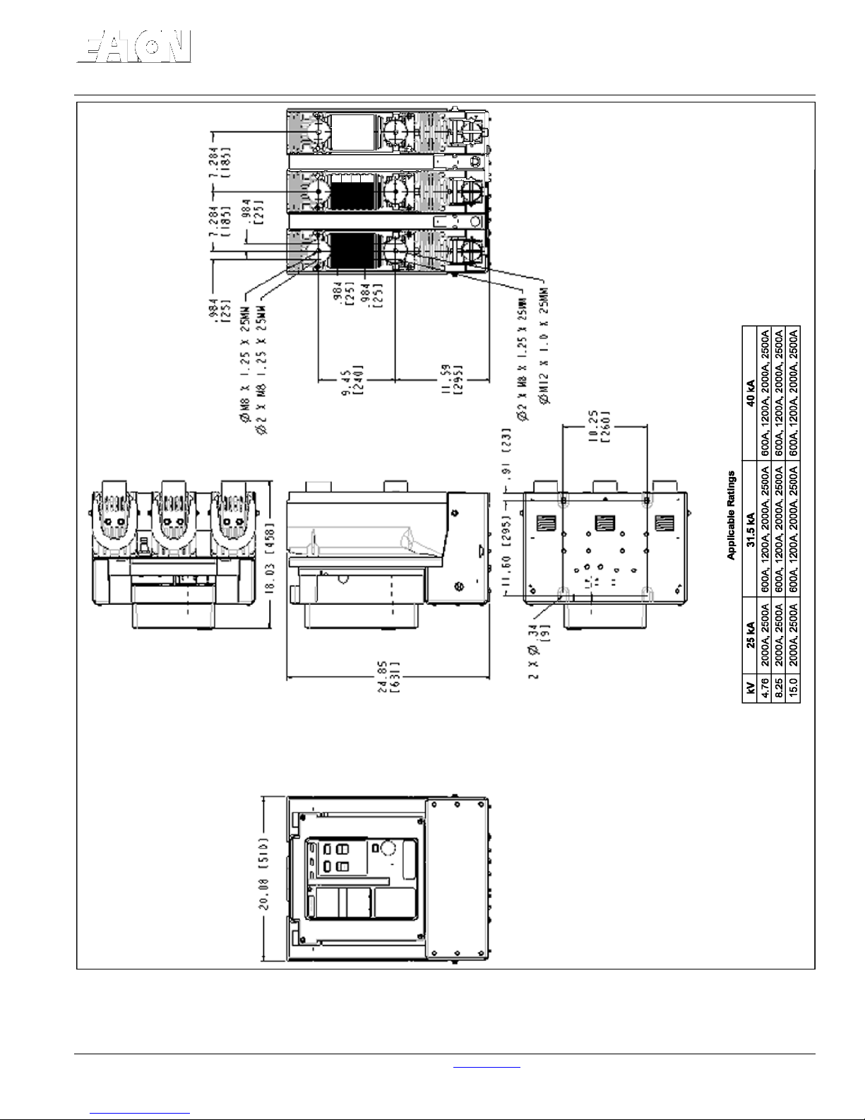
Effective: November 2017 Page 7
Figure 1-4 VCP-TR Fixed Breaker Outlines in inches [mm] (Refer to above Applicable Ratings Table)
IB131016EN For more information visit: www.Eaton.com
Instruction Book
Effective: November 2017 Page 8
Figure 1-5 VCP-T Drawout Breaker Outlines in inches [mm] (Refer to above Applicable Ratings Table)
For more information visit: www.Eaton.com IB131016EN
Instruction Book
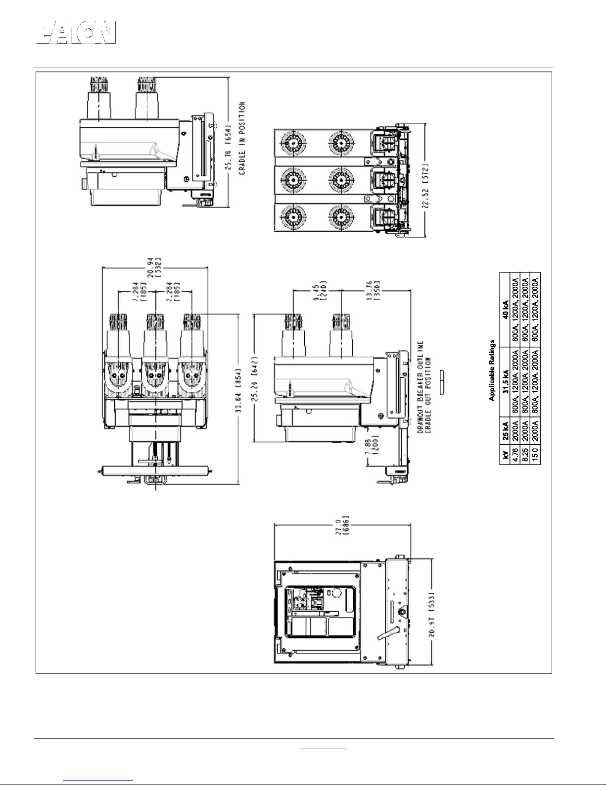
Effective: November 2017 Page 9
Figure 1-6 VCP-T Breaker Cassette Outline s in inch es [mm ] (Re fer to abo ve Applicab le Ra tings Ta ble)
IB131016EN For more information visit: www.Eaton.com

Instruction Book
Effective: November 2017 Page 10
REFER TO IL131031EN FOR:
VCP-T/T-VAC 31.5kA, 40kA 2000A Cassette Bus Bar
Assembly Instructions
For more information visit: www.Eaton.com IB131016EN

Instruction Book
Effective: November 2017 Page 11
SECTION 2: SAFE PRACTICES
The circuit breakers are equipped with high speed,
high energy operating mechanisms. They are
designed with built-in safety interlocks to provide for
safe operation. In addition, other optional interlocks
are available depending upon the application. Refer to
Section 5 for additional inter lock informatio n. It is the
customers’ responsibility to insure that appropriate
interfaces with the breakers are provided and tests
conducted to adequately prove proper installation and
functioning.
WARNING
TO PROTECT THE PERSONNEL ASSOCIATED
WITH INSTALLATION, OPERATION, AND
MAINTENANCE OF THESE BREAKERS, THE
FOLLOWING PRACTICES MUST BE FOLLOWED:
Always make sure that primary and secondary
power are disconnected from a fixed breaker
before performing any maintenance. Failure to do
so could result in electrical shock leading to death,
severe personal injury and/or property damage.
Do not work on a closed breaker or a breaker with
closing springs charged. The closing springs
should be discharged and the main contacts open
before working on the breaker. Failure to do so
could result in cutting or crushing injuries.
Do not use a circuit breaker by itself as the sole
means of isolating a high voltage circuit. As
appropriate, use an isolation means and follow all
lock-out and tagging rules of the Local Electrical
Codes and any and all applicable codes,
regulations and work rules.
Only qualified persons, as defined in the Local
Electrical Codes, who are familiar with the
installation and maintenance of medium voltage
circuits and equipment, should be permitted to
work on these breakers.
Read these instructions carefully before
attempting any installation, operation or
maintenance of these breakers.
Always remove drawout type breakers from their
enclosure before performing any maintenance.
Failure to do so could result in electrical shock
leading to death, severe personal injury and/or
property damage.
Always ensure that drawout circuit breakers are in
one of their designed cell positions, such as
Connect, Test/Disconnect or Remove. A circuit
breaker permitted to remain in an intermediate
position could result in control circuits being
improperly connected resulting in electrical failures.
Breakers are equipped with safety interlocks. Do
Not defeat them. This may result in death, bodily
injury and/or equipment damage.
Do not work on a circuit breaker while
suspended from a lifting means. Maintenance
work should be performed on a properly
supported cart or table.
IB131016EN For more information visit: www.Eaton.com
Instruction Book
Effective: November 2017 Page 12
3-2.1 UNPACKING
SECTION 3: RECEIVING, HANDLING
AND STORA GE
VCP-T and VCP-TR circuit breakers are subjected to
complete factory production tests and inspection
before being packed. They are shipped in packages
designed to provide maximum protection to the
equipment during shipment and storage and at the
same time to provide convenient handling.
3-1 RECEIVING
Until the breaker is ready for use, it is best NOT to
remove it from its container. If the breaker is to be
placed in storage, maximum protection can be obtained
by keeping it packed as shipped.
Upon receipt of the equipment, inspect the containers
for any signs of damage from rough handling and/or
external damage incurred during the transportation
phase. Record any observed damage for reporting to
the transportation carrier and Eaton. All reports should
be as specific as possible and include the order
number and other applicable nameplate information.
Every effort is made to ensure that circuit breakers
arrive at their destination undamaged and ready for
installation. Care should be exercised, however, to
protect the breakers from impact at all times. Do not
remove protective packaging until the circuit breakers
are ready for inspection, testing and/or installation.
Before beginning to unpack new circuit breakers, read
and understand the directions. Unpacking a fixed circuit
breaker is described in the next paragraph in detail.
Unpacking a drawout circuit breaker is also simple to
accomplish and is not described here in detail. Just
proceed by carefully removing all packing material used
for protection during shipment and the fa steners used
to secure the drawout circuit breaker to its shipping
pallet.
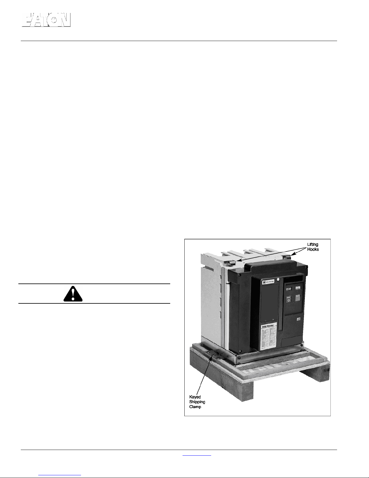
When ready to inspect and install the circuit breaker,
carefully remove any banding straps and lift off the
cardboard box. Remove any additional packing material
and internally packed documentation. The circuit
breaker is mounted to a wooden shipping pallet. A
keyed metal clamp is used on each side of the circuit
breaker to hold it to the wooden pallet (Figure 3-1).
Remove the screws from the wooden pallet on each
side and lift up and out on the keyed metal clamps for
removal (Figure 3-2). The circuit breaker is now ready
to be rem ov e d f r o m i ts s hi p ping pallet. Save all
shipping hardware and packaging material for any
future shipments of the circuit breaker.
3-2 HANDLING
WARNING
DO NOT USE ANY LIFTING DEVICE AS A
PLATFORM FOR PERFORMING MAINTENANCE,
REPAIR OR ADJUSTMENT OF THE BREAKER,
FOR OPENING OR CLOSING THE CONTACTS OR
CHARGING THE SPRINGS. THE BREAKER MAY
SLIP OR FALL CAUSING SEVERE PERSONAL
INJURY. ALWAYS PERFORM MAINTENANCE,
REPAIR AND ADJUSTMENTS ON A WORKBENCH
CAPABLE OF SUPPORTING THE BREAKER.
Shipping containers are designed to be handled either
by use of a sufficiently strong rope sling and overhead
lifting device or by a fork lift truck. If containers must
be skidded for any distance, it is preferable to use
roller conveyors or individual pipe rollers.
Figure 3-1 Fixed Breaker Shown Mounted on Pallet
For more information visit: www.Eaton.com IB131016EN
Instruction Book
Effective: November 2017 Page 13
IB131016EN For more information visit: www.Eaton.com
Instruction Book
Effective: November 2017 Page 14
3-3 STORAGE
WARNING
THE CUSTOMER SHOULD READ AND
UNDERSTAND THE MATERIAL PRESENTED AND
ANY WARNINGS OR CAUTIONS OFFERED IN
THE INSTRUCTION BOOK BEFORE ANY
ATTEMPT IS MADE TO INTERFACE WITH THIS
CIRCUIT BREAKER.
IT IS IMPERATIVE THAT ALL APPLICABLE ANSI
STANDARDS BE COMPLIED WITH IN EVERY
RESPECT AND THAT NO COMPROMISES ARE
MADE WITH RESPECT TO THE ANSI
GUIDELINES OR INTENT.
UNDER NO CIRCUMSTANCES SHOULD
ALTERATIONS BE MADE TO EATON SUPPLIED
VCP-T OR VCP-TR CIRCUIT BREAKERS UNLESS
THE ALTERATION IS SPECIFICALLY ADDRESSED
IN AND PERMITTED BY THIS INSTRUCTION
BOOK.
If the circuit breaker is to be placed in storage,
maximum protection can be obtained by keeping it
packed as shipped. Before placing it in storage,
checks should be made to make sure that the breaker
is fre e from shipping damage and is in satisfactory
operating condition.
Outdoor storage is NOT recommended. If
unavoidable, the outdoor location must be well
drained and a temporary shelter from sun, rain, snow,
corrosive fumes, dust, dirt, falling objects, excessive
moisture, etc. must be provided. Containers should be
arranged to permit free circulation of air on all sides
and temporary heaters should be used to minimize
condensation. Moisture can cause rusting of metal
parts and deterioration of high voltage insulation. A
heat level of approximately 400 watts for each 100
cubic feet of volume is recommended with the heaters
distributed uniformly throughout the structure near the
floor.
Indoor storage should be in a building with sufficient
heat and circulation to prevent condensation. If the
building is not heated, the same general rule for heat as
for outdoor storage should be applied.
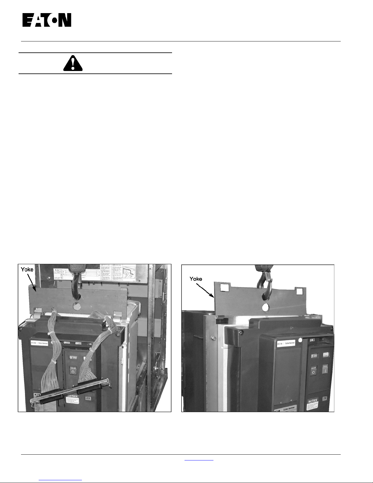
Figure 3-4 Preferred Lifting Method Using Lifting Yoke
To Lift 25kA Breaker
For more information visit: www.Eaton.com IB131016EN
Figure 3-4a Preferred Lifting Method Using Lifting
Yoke To Lift 40kA Breaker
Instruction Book
Effective: November 2017 Page 15
3-4 TYPICAL BREAKER AND CASSETTE WEIGHTS
Table 3.1 Circuit Breaker and Cassette Weights Table 3.1 (Continued)
Circuit
Breaker
Type
50 VCP-TR16
and
50 VCP-T16
50 VCP-TR20
and
50 VCP-T20
50 VCP-TR25
and
50 VCP-T25
50 VCP-TR32
and
50 VCP-T32
50 VCP-TR40
and
50 VCP-T40
Current
Rating
(Amps)
600
1200
1600
600
1200
1600
600
1200
1600
2000
2500
600
1200
1600
2000
2500
600
1200
1600
2000
2500
Approximate Weight
(lb)
Fixed Drawout Cassette Fixed Drawout Cassette
153
155
157
159
161
163
166
168
170
338
342
329
329
333
338
342
333
333
338
342
346
232
234
237
237
239
241
243
245
247
428
NA
419
419
424
428
NA
424
424
428
432
NA
157
157
157
157
157
157
157
157
157
157
NA
301
301
301
301
NA
301
301
301
301
NA
Circuit
Breaker
Type
150 VCP-TR16
150 VCP-T16
150 VCP-TR20
150 VCP-T20
150 VCP-TR25
150 VCP-T25
150 VCP-TR32
150 VCP-T32
150 VCP-TR40
150 VCP-T40
and
and
and
and
and
Current
Rating
(Amps)
600
1200
1600
600
1200
1600
600
1200
1600
2000
2500
600
1200
1600
2000
2500
600
1200
1600
2000
2500
Approximate Weight
(lb)
155
157
159
161
163
166
168
170
172
342
346
333
333
338
342
346
338
338
342
346
350
234
237
239
239
241
243
245
247
249
432
NA
424
424
428
432
NA
428
428
432
436
NA
161
161
161
161
161
161
161
161
161
161
NA
301
301
301
301
NA
301
301
301
301
NA
75 VCP-TR16
and
75 VCP-T16
75 VCP-TR20
and
75 VCP-T20
75 VCP-TR25
and
75 VCP-T25
75 VCP-TR32
and
75 VCP-T32
75 VCP-TR40
and
75 VCP-T40
600
1200
1600
600
1200
1600
600
1200
1600
2000
2500
600
1200
1600
2000
2500
600
1200
1600
2000
2500
155
157
159
161
161
163
166
168
170
342
346
333
333
338
342
346
333
333
338
342
346
232
234
237
239
241
243
245
247
249
432
NA
424
424
428
432
NA
424
424
428
432
NA
161
161
161
161
161
161
161
161
161
161
NA
301
301
301
301
NA
301
301
301
301
NA
IB131016EN For more information visit: www.Eaton.com
Instruction Book
Effective: November 2017 Page 16
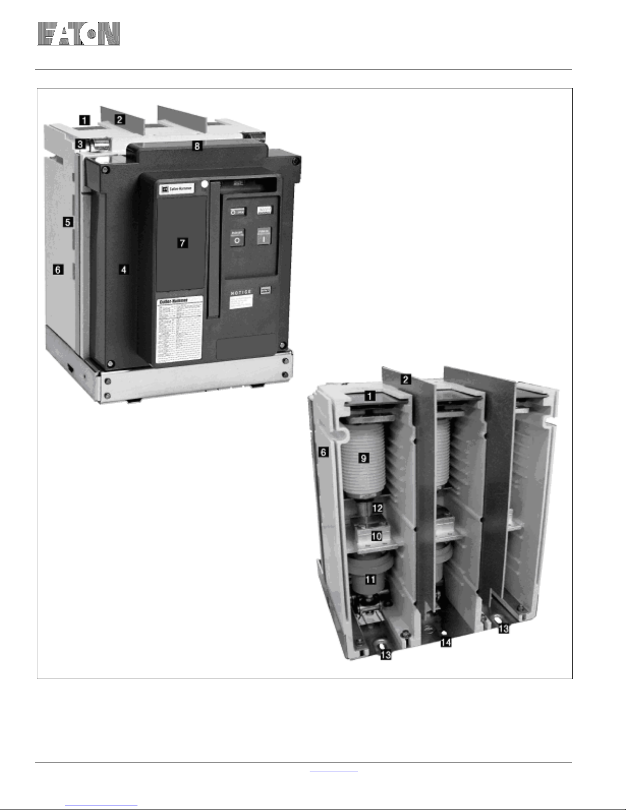
8. Secondary Disconnect with Protective
Hood
9. Vacuum Interrupter (Part of Replacement
Pole Unit Assembly - 67A3158 or
67A3159 or 67A3160, depending on kA
and AMP rating.
10. Primary Conductor Interface or
Bottom Conductor – 69C3008H03
11. Drive Insulator with Internal Contact
Loading Spring (Wipe Spring)
16kA – 69C3053G01
25kA - 69C3053G03
12. Vacuum Interrupter Movable Stem
13. Rear Customer Mounting Holes
69C3010G01 – Base Plate
14. Customer Earth Connection
69C3010G01 - Base Plate
1. Horizontal Phase Barrier (95kV BIL Only)
68B3016H02
2. Vertical Phase Barrier (95kV BIL Only)
69C3027G01
3. Integral Lifting Hook
67A3137H01
4. Front Cover (Figure 3-10 for details)
69C3056G01
5. 3mm Earthed Steel Barrier
69C3104H03
6. Pole Unit Molding 70D3001G01
7. Trip Unit Location (Non-Automatic Breaker
Shown)
Figure 3-5 Front and Rear Views All VCP-TR Fixed (except 25kA, 2000/2500A and all 31.5/40kA)
For more information visit: www.Eaton.com IB131016EN
Instruction Book
Effective: November 2017 Page 17
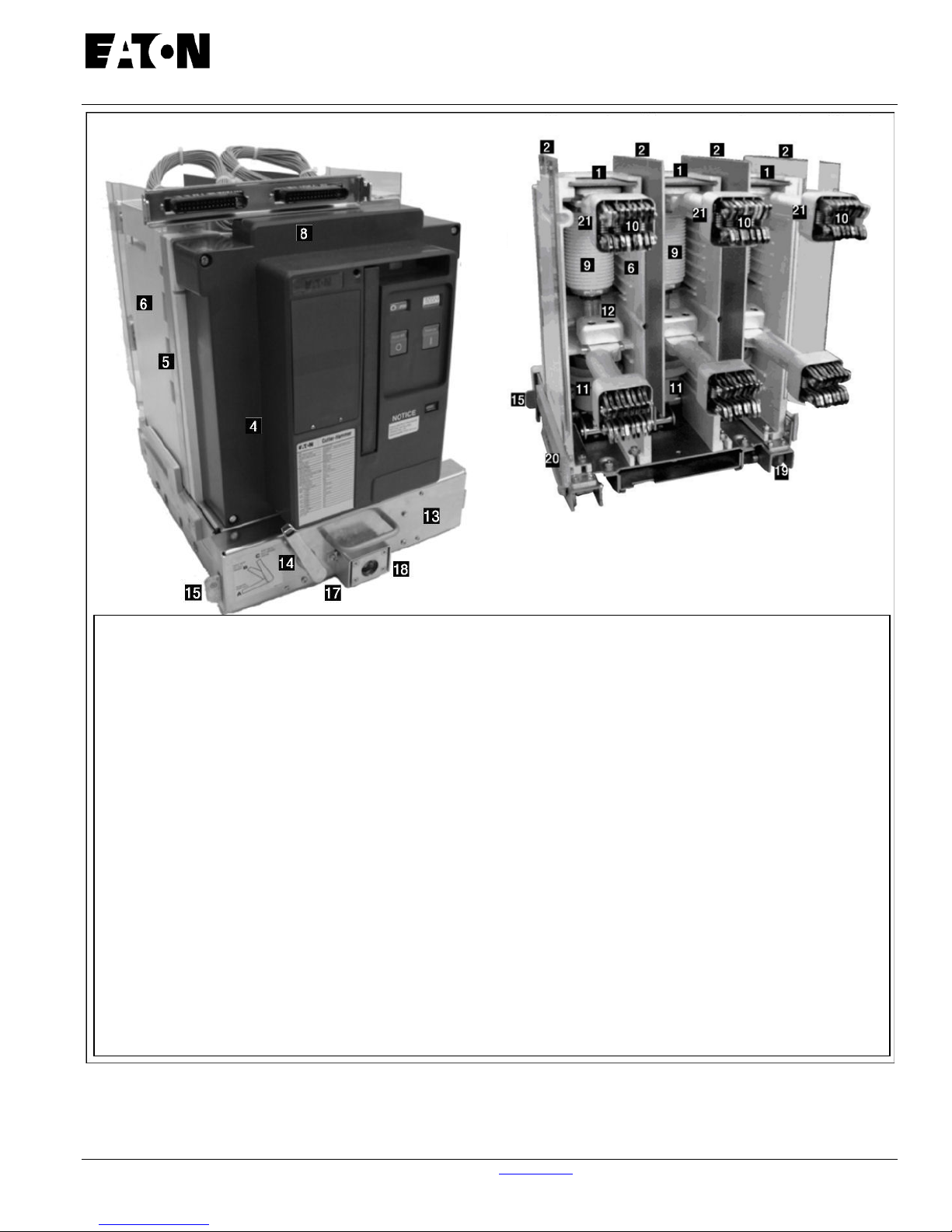
1. Horizontal Phase Barrier – 95kV BIL Only 68B3106H02
2. Vertical Phase Barrier – 95kV BIL Only 69C3027G01
3. Integral Lifting Hook 67A3137H01
4. Front Cover 69C3056G01
5. 11 Gauge Grounded Steel Barrier 69C3104H03
6. Pole Unit Molding 70D3001G01
8. Secondary Disconnect Protective Hood (Umbilical Cord Shown)
Umbilical Harness Assembly 69C3261G01
9. Vacuum Interrupter (This is part of the Pole Unit Assembly)
67A3158, 67A3159, or 67A3160 (Depending on the kA and AMP Rating)
(Contact your Eaton Sales or Local Eaton Rep. for more information).
10. Primary Disconnect Finger Cluster (1200/1250A Shown)
1200/1250A – 68B3031G01 600/630A - 68B3031G02
11. Drive Insulator with Internal Contact Loading Spring (Wipe Spring).
16kA – 69C3053G01 25kA – 69C3053G03
12. Vacuum Interrupter Movable Stem
13. Cradle with Levering Mechanism 25kA – 69C3305G01 40kA – 69C3305G11
14. Shoot Bolt Handle – Part of 69C3305
15. Shoot Bolt - Part of 69C3305
16. Push/Pull Handle – Part of 69C3305
17. Racking Screw Lock Plate – Part of 69C3305
18. Levering Drive Nut – Part of 69C3305
19. Integral Wheel – Wheel 67A3201H01 Wheel Axle (Pin) – 67A3202H02
20. Shutter Operator – 69C3213H05
21. Primary Disconnect Cup (95kV BIL Only) – 68B3303H01
Figure 3-6 Front and Rear Views All T-VAC Draw out (except 25kA, 2000A and all 3 1.5/40
IB131016EN For more information visit: www.Eaton.com
 Loading...