

Eaton 72W-VAC20, 72W-VAC25, 72W-VAC32, 72W-VAC40, 120W-VAC16 Instructions For Installation, Operation And Maintenance
...
A
A
r
A
r
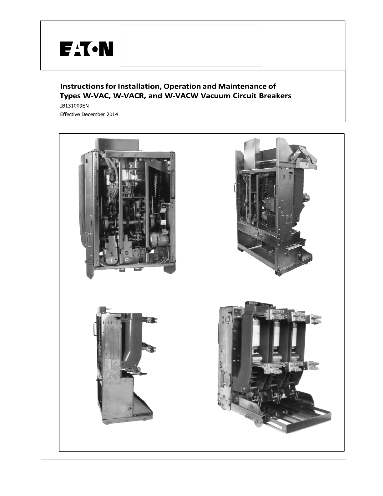
W-VAC Breaker Element
W-VAC3150A Breaker with Carriage
ssembly for Single Tier Switchgear
W-VAC Breaker with Carriage
ssembly for Single Tier Switchgea
W-VAC Breaker with Cradle
ssembly for Double Tier Switchgea
IB131009EN


WARNING WARNING
IMPROPERLY INSTALLING OR MAINTAINING
THESE PRODUCTS CAN RESULT IN DEATH, SERIOUS PERSONAL INJURY, OR PROPERTY DAMAGE.
READ AND UNDERSTAND THESE INSTRUCTIONS
BEFORE ATTEMPTING ANY UNPACKING, ASSEMBLY, OPERATION OR MAINTENANCE OF THE CIRCUIT BREAKERS.
INSTALLATION OR MAINTENANCE SHOULD BE
ATTEMPTED ONLY BY QUALIFIED PERSONNEL.
THIS INSTRUCTION BOOK SHOULD NOT BE CONSIDERED ALL INCLUSIVE REGARDING INSTALLATION OR MAINTENANCE PROCEDURES. IF FURTHER INFORMATION IS REQUIRED, YOU SHOULD
CONTACT EATON.
Eaton Corporation
Power Components Division
Instruction Book
Page3
THE CIRCUIT BREAKER ELEMENTS DESCRIBED IN
THIS BOOK ARE DESIGNED AND TESTED TO
OPERATE WITHIN THEIR NAMEPLATE RATINGS.
OPERATION OUTSIDE OF THESE RATINGS MAY
CAUSE THE EQUIPMENT TO FAIL, RESULTING IN
DEATH, BODILY INJURY AND PROPERTY DAMAGE.
ALL SAFETY CODES, SAFETY STANDARDS
AND/OR REGULATIONS AS THEY MAY BE
APPLIED TO THIS TYPE OF EQUIPMENT MUST BE
STRICTLY ADHERED TO.
THESE CIRCUIT BREAKER ELEMENTS ARE
DESIGNED TO BE INSTALLED PURSUANT TO THE
AMERICAN NATIONAL STANDARDS INSTITUTE
(ANSI). SERIOUS INJURY, INCLUDING DEATH, CAN
RESULT FROM FAILURE TO FOLLOW THE PROCEDURES OUTLINED IN THIS MANUAL. THESE CIRCUIT BREAKER ELEMENTS ARE SOLD PURSUANT
TO A NON-STANDARD PURCHASING AGREEMENT
WHICH LIMITS THE LIABILITY OF THE MANUFACTURER.
All possible contingencies which may arise during installation, operation or maintenance, and all details and
variations of this equipment do not purport to be covered by these instructions. If further information is
desired by purchaser regarding his particular installation, operation or maintenance of particular equipment,
contact an Eaton representative.
IB131009EN

InstructionBook
Page 4
TABLE OF CONTENTS
SECTION 1 INTRODUCTION
1-1
Type W-VAC, W-VACR and W-VACW Breaker Ratings ....................................................................................... 1
SECTION 2 SAFE PRACTICES
SECTION 3 RECEIVING, HANDLING AND STORAGE
3-1 Receiving ............................................................................................................................................................... 14
3-2 Handling ................................................................................................................................................................ 15
3-3 Storage .................................................................................................................................................................. 15
SECTION 4 INSTALLATION
4-1 Initial Inspection and Operation ............................................................................................................................ 22
4-2 Manual Operation Check ...................................................................................................................................... 22
4-3 Vacuum Interrupter Integrity ................................................................................................................................. 22
4-4 Insulation ............................................................................................................................................................... 22
4-5 Contact Erosion and Wipe .................................................................................................................................... 22
4-6 Primary Circuit Resistance .................................................................................................................................... 22
4-7 Nameplate ............................................................................................................................................................. 22
4-8 Electrical Operations Check .................................................................................................................................. 22
4-9 Breaker/Compartment Interface Check ................................................................................................................ 24
PAGE
SECTION 5 DESCRIPTION AND OPERATION
5-1 Interrupter Assembly ............................................................................................................................................. 26
5-1.1 Vacuum Interrupter ............................................................................................................................................... 26
5-1.2 Contact Erosion Indicator (Except 3150A) ........................................................................................................... 27
5-1.3 Contact Erosion Indicator (3150A Only) ............................................................................................................... 27
5-1.4 “T” Cutout Loading Spring Indicator ...................................................................................................................... 28
5-1.5 Contact Wipe and Stroke ...................................................................................................................................... 28
5-1.6 Pole Unit Support Molding .................................................................................................................................... 28
5-2 Stored Energy Mechanism .................................................................................................................................... 29
5-2.1 Operation of Stored Energy Mechanism .................................................................................... .......................... 29
5-2.2 Charging ................................................................................................................................................................ 29
5-2.3 Closing Operation .................................................................................................................................................. 29
5-2.4 Tripping Operation................................................................................................................................................. 32
5-2.5 Trip Free Operation ............................................................................................................................................... 32
5-3 Control Scheme ............................................................................................................
5-3.1 Timing .................................................................................................................................................................... 32
5-3.2 Secondary Disconnects ........................................................................................................................................ 32
5-3.3 Undervoltage Trip Device...................................................................................................................................... 33
5-4 Interlocks ............................................................................................................................................................... 33
5-4.1 Floor Tripping, Spring Release and Anti-Latch Interlocks .................................................................................... 33
5-4.2 Levering Interlock .................................................................................................................................................. 33
5-4.3 Anti-Close Interlock ............................................................................................................................................... 33
5-4.4 Earthing Drive Interlock ......................................................................................................................................... 33
........................................ 32
IB131009EN

Instruction Book
Page5
5-5 Miscellaneous ........................................................................................................................................................ 36
5-5.1 Earthing Contact .................................................................................................................................................... 36
5-5.2 Operations Counter ............................................................................................................................................... 36
5-6 Levering Mechanism .............................................................................................................................................. 36
5-7 Circuit Breaker Interfacing ..................................................................................................................................... 36
5-7.1 Electrical Clearances ............................................................................................................................................. 36
SECTION 6 INSPECTION AND MAINTENANCE
6-1 Warning .................................................................................................................................................................. 37
6-2 Frequency of Inspection ........................................................................................................................................ 37
6-3 Inspection and Maintenance Procedures .............................................................................................................. 38
6-4 Vacuum Interrupter Integrity Test .......................................................................................................................... 37
6-5 Contact Erosi on (Except 3150A) ........................................................................................................................... 40
6-5.1 Contact Erosion (3150A Only) .............................................................................................................................. 40
6-5.2 Contact Wipe (All Ratings) .................................................................................................................................... 40
6-6 Insulation ................................................................................................................................................................ 41
6-7 Insulation In tegrity Check ...................................................................................................................................... 41
6-8 Primary Circuit Resistance Check ......................................................................................................................... 42
6-9 Mechanism Check ................................................................................................................................................. 42
6-9.1 CloSure Test .......................................................................................................................................................... 42
6-10 Lubrication .......................................................................................................................................................... 47
6-11 Troubleshooting Chart ........................................................................................................................................ 47
SECTION 7 RENEWAL PARTS
7-1 General .................................................................................................................................................................. 50
7-2 Ordering In structions ............................................................................................................................................. 50
FIGURES
Figure Title Page
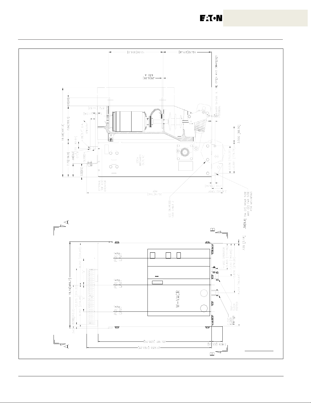
1-1 Type W-VACR 630A Breaker Element Only Outline Dimensions (millimeters) & Weights (Kilograms) .... 3
1-2 Type W-VACR 630A Breaker Element Only Outline Dimensions (millimeters) & Weights (Kilograms) .... 4
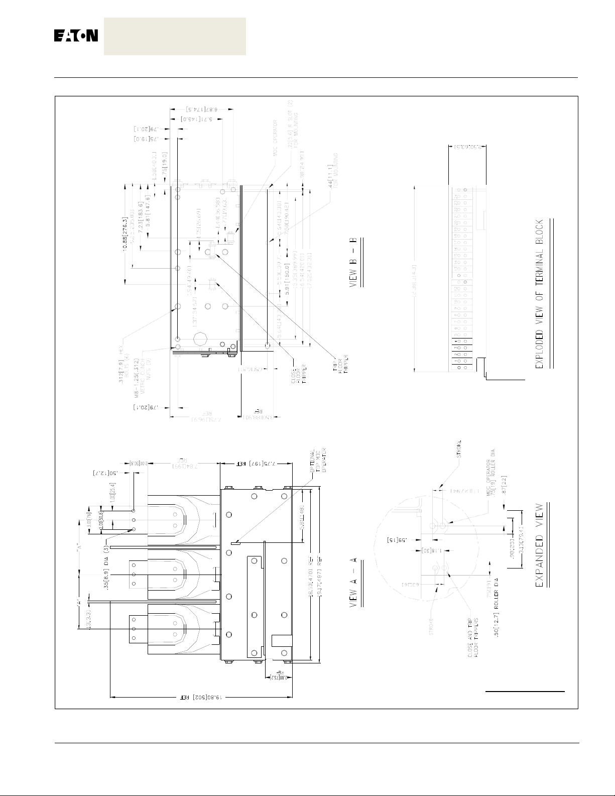
1-3 Type W-VACR 800/1250A Breaker Element Only Outline Dimensions (millimeters) & Weights (kg) ....... 5
1-4 Type W-VACR 800/1250A Breaker Element Only Outline Dimensions (millimeters) & Weights (kg) ....... 6
1-5 Type W-VACR 800/1250A Breaker Element Only Outline Dimensions (millimeters) & Weights (kg) ....... 7
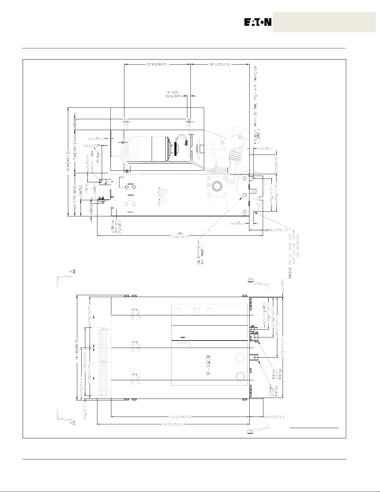
1-6 Type W-VACR 2000A Breaker Element Only Outline Dimensions (millimeters) & Weights (kg) .............. 8
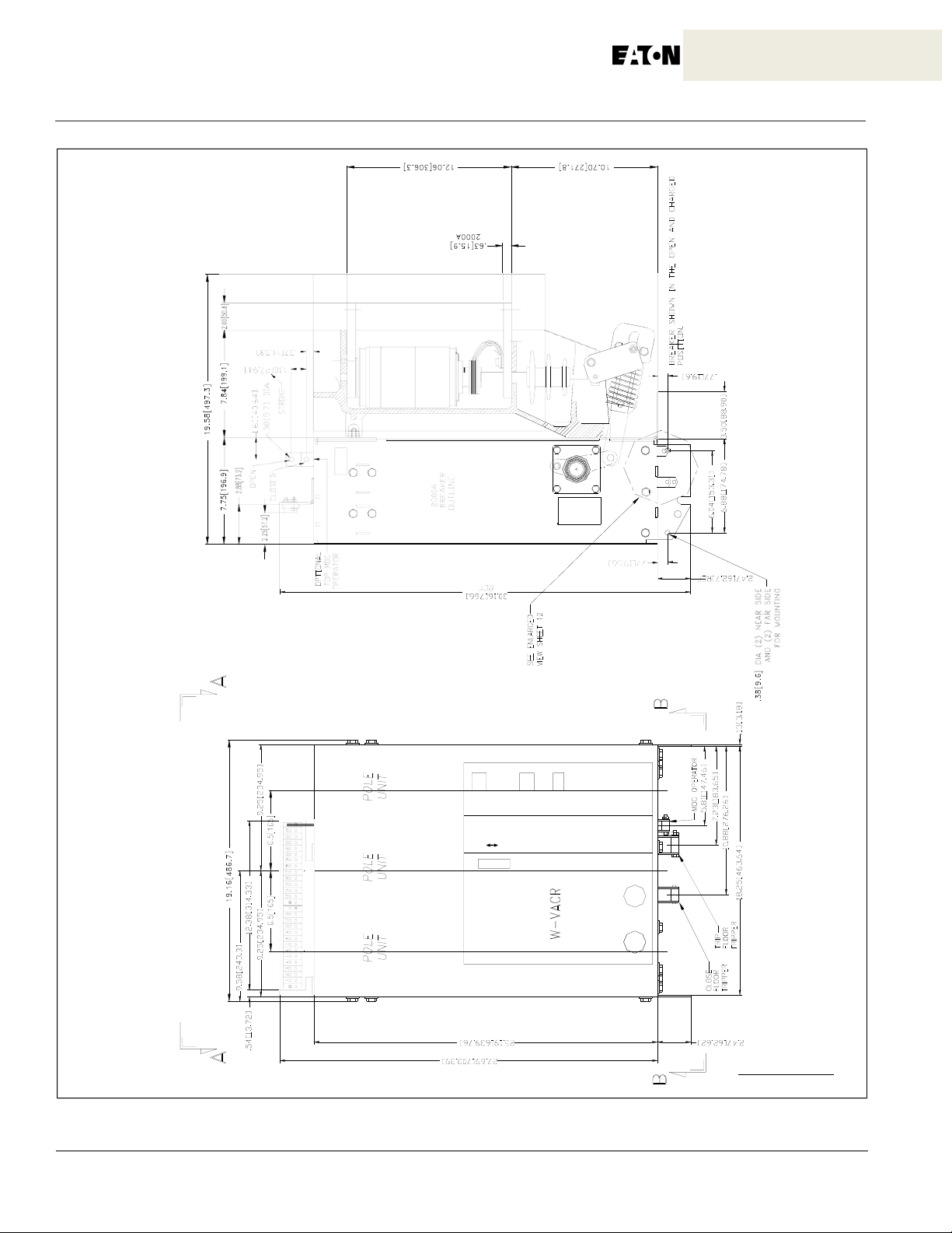
1-7 Type W-VACR 2500A Breaker Element Only Outline Dimensions (millimeters) & Weights (kg) .............. 9
1-8 Type W-VAC Breaker Element Only Outline Dimensions (millimeters) and Weights (Kilograms) .......... 10
1-9 Outline and Dimensions (mm) Type W-VAC B reaker Element with Carri age
Assembly and Cradle Assembly ........................................................................................................................ 11
1-10 Outline and Dimensions (mm) Type W-VAC 3150 Breaker with Carriage Assembly .............................. 12
3-1 Typical VCP-W Tools and Accessories .......................................................................................................14
3-2 Typical Front View VCP-W Vacuum Circuit Breaker Element ................................................................... 16
3-3 Typical VCP-W Vacuum Circuit Breaker Element with Front Cover Removed ....................................... 17
3-4 Typical Rear View VCP-W Vacuum Circuit Breaker Element ................................................................... 18
3-5 Typical VCP-W Vacuum Circuit Breaker Element Escutcheon ................................................................. 19
3-6 Front and Rear External View W-VAC Breaker With Cradle Assembly for
Double Tier Switchgear ...............................................................................................................................20
3-7 Front and Rear External View W-VAC 3150A Breaker with Carriage Assembly for
Single Tier Switchgear .................................................................................................................................21
IB131009EN

InstructionBook
Page 6
4-1 Type W-VAC Breaker Manual Operation (Single Tier Breaker Shown) .................................................. 23
5-1 Flush Mounted Configuration. ..................................................................................................................... 26
5-2 Behind the Door Configuration ................................................................................................................... 27
5-3 Closeup of Type W-VAC Breaker Vacuum Interrupters and Current Carrying System ........................... 27
5-4 a Type W-VAC 95 kV BIL Breaker Shown With Left Hand Cover Removed for Clarity Purposes ............. 28
5-4 b Type W-VAC 3150 Ampere Breaker Closeup of Completely Enclosed Pole Units ................................. 28
5-5 Closing Cam and Trip Linkage ................................................................................................................... 30
5-6 Charging Schematic .................................................................................................................................... 31
5-7 Typical DC and AC Control Schemes. ..................................................................................................... 34
5-8 Undervoltage Trip Device Configuration ..................................................................................................... 35
5-9 Closeup of Type W-VACW Breaker Vacuum Interrupters and Current Carrying System ....................... 36
6-1 Lubrication Points ........................................................................................................................................ 37
6-2 Vacuum Interrupter Showing Contact Erosion Indicator With Breaker Open .......................................... 40
6-3 Vacuum Interrupter Showing Contact Erosion Indicator With Breaker Closed ........................................ 40
6-4 Breaker Sho wn Closed an d Interrupte r Erosi on Satisfactory (3 150A). .................................................... 41
6-5 Breaker Sho wn Col sed an d Interrupter Erosi on Unsa tisfacto ry (31 50A). ................................................ 41
6-6 “T” Contact Wipe Indicator .......................................................................................................................... 42
6-7 Wipe Indication ............................................................................................................................................ 42
TABLES
Table
Title
1.1 Type W-VAC and W-VACW Vacuum Circuit Breaker Ratings .................................................................... 1
1.2 Type W-VACR Vacuum Circuit Breaker Ratings ......................................................................................... 2
5.1 Typical Opening and Closing Times Value ................................................................................................ 32
6.1 Test Voltage. ............................................................................................................................................... 39
6.2 Typical Resistance Measurements ............................................................................................................. 42
7.1 Recommended W-VAC and W-VACW Spare Parts .................................................................................. 50
Page
IB131009EN
r
SECTION 1: INTRODUCTION
The purpose of this book is to provide instructions for
unpacking, storage, installation, operation and maintenance of Types W-VAC, W-VACR, and W-VACW
Vacuum Circuit Breakers. They are a horizontal drawout
type removable interrupting element design, unless
there is an “R” in the designation.The “R” as in W-VACR
indicates a fixed breaker configuration. They were
designed specifically to IEC 56 Standards for reliable
performance. All types can be applied in single tier or
double tier switchgear applications, with the basic
breaker element applicable to retrofitting. Reliable control and protection are achieved though the use of the
W-VAC family of breakers.
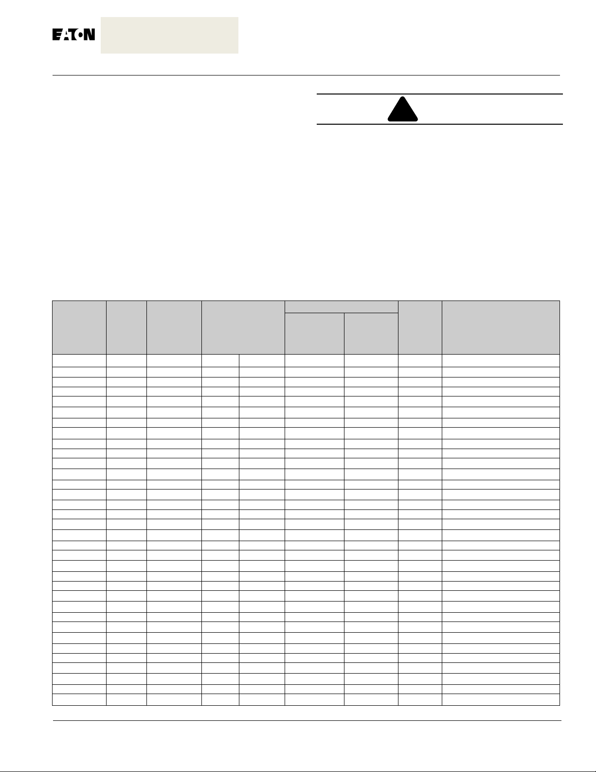
1-1 W-VAC, W-VACR AND W-VACW RATINGS
Table 1.1 Type W-VAC and W-VACW Vacuum Circuit Breaker Ratings
Circuit
Breaker
Type
36W-VAC25
72W-VAC16
72W-VAC20
72W-VAC25
72W-VAC32
72W-VAC40
120W-VAC16
120W-VAC20
120W-VAC25
120W-VAC32
120W-VAC40
120W-VAC50
150W-VAC16
150W-VAC20
150W-VAC25
150W-VAC32
150W-VAC40
150W-VAC50
175W-VAC16
175W-VAC20
175W-VAC25
175W-VAC32
175W-VAC40
120W-VACW16
120W-VACW20
120W-VACW25
120W-VACW32
120W-VACW40
150W-VACW16
150W-VACW20
150W-VACW25
150W-VACW32
150W-VACW40
Rated
Frequency
Voltage
at
50-60HZ
3.6 50/60 25 3 40 10 63
7.2 50/60 16 3 60 20 40
7.2 50/60 20 3 60 20 50
7.2 50/60 25 3 60 20 63
7.2 50/60 31.5 3 60 20 79
7.2 50/60 40 3 60 20 100 3150
12 50/60 16 3 75 28 40
12 50/60 20 3 75 28 50
12 50/60 25 3 75 28 63
12 50/60 31.5 3 75 28 79
12 50/60 40 3 75 28 100
12 50/60 50 3 75 28 125 3150
15 50/60 16 3 95 36 40
15 50/60 20 3 95 36 50
15 50/60 25 3 95 36 63
15 50/60 31.5 3 95 36 79
15 50/60 40 3 95 36 100 3150
15 50/60 50 3 95 36 125 3150
17.5 50/60 16 3 95 38 40
17.5 50/60 20 3 95 38 50
17.5 50/60 25 3 95 38 63
17.5 50/60 31.5 3 95 38 79
17.5 50/60 40 3 95 38 100 3150
12 50/60 16 3 75 42 40
12 50/60 20 3 75 42 50
12 50/60 25 3 75 42 63
12 50/60 31.5 3 75 42 79
12 50/60 40 3 75 42 100
15 50/60 16 3 95 42 40
15 50/60 20 3 95 42 50
15 50/60 25 3 95 42 63
15 50/60 31.5 3 95 42 79
15 50/60 40 3 95 42 100
kV
Hz
Rated Short Circuit
Breaking Current
& Short Circuit
Duration
kA
Sec
SATISFACTORY PERFORMANCE OF THESE
BREAKERS IS CONTINGENT UP-ON PROPER
APPLICATION, CORRECT INSTALLATION AND
ADEQUATE MAINTENANCE. THIS INSTRUCTION
BOOK MUST BE CAREFULLY READ AND FOLLOWED IN ORDER TO OBTAIN OPTIMUM PERFORMANCE FOR LONG USEFUL LIFE OF THE CIRCUIT
BREAKERS.
TYPES W-VAC, W-VACR AND W-VACW BREAKERS
ARE PROTECTIVE DEVICES, AS SUCH, THEY ARE
MAXIMUM RATED DEVICES. THEREFORE, THEY
SHOULD NOT UNDER ANY CIRCUMSTANCES BE
APPLIED OUTSIDE THEIR NAMEPLATE RATINGS.
Rated Insulation Level
Lighting
Pulse
Withstand
Voltage
kV
Powe
Frequency
Withstand
Voltage
kV
Short
Circuit
Making
Current
kA
Instruction Book
WARNING
Rated Nominal Current
(Peak) Amperes
630, 1250, 2000,3150
630, 800, 1250
630, 800, 1250, 1600
630, 800, 1250, 1600, 2000,3150
1250, 2000
630, 800, 1250
630, 800, 1250, 1600
630, 800, 1250, 1600, 2000,3150
1250, 2000
1250, 2000,3150
630, 800, 1250
630, 800, 1250, 1600
630, 800, 1250, 1600, 2000,3150
1250, 2000
630, 800, 1250
630, 800, 1250, 1600
630, 800, 1250, 1600, 2000,3150
630, 800, 1250, 1600
630, 800, 1250
630, 800, 1250, 1600
630, 800, 1250, 1600, 2000
1250, 1600, 2000
1250, 2000
630, 800, 1250
630, 800, 1250, 1600
630, 800, 1250, 1600, 2000
1250, 2000
1250, 2000
Page1
IB131009EN
r
InstructionBook
Page 2
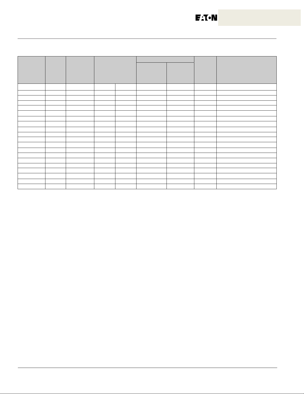
Table 1.2 Type W-VACR Vacuum Circuit Breaker Ratings
Circuit
Breaker
Type
36W-VACR16
36W-VACR20
36W-VACR25
72W-VACR16
72W-VACR20
72W-VACR25
72W-VACR32
72W-VACR40
120W-VACR16
120W-VACR20
120W-VACR25
120W-VACR32
120W-VACR40
120W-VACR50
150W-VACR16
150W-VACR20
150W-VACR25
150W-VACR32
150W-VACR40
Rated
Frequency
Voltage
at
50-60HZ
kV
3.6 50/60 16 3 40 20 40
3.6 50/60 20 3 40 20 50
3.6 50/60 25 3 40 20 63
7.2 50/60 16 3 60 20 40
7.2 50/60 20 3 60 20 50
7.2 50/60 25 3 60 20 63
7.2 50/60 31.5 3 60 20 80
7.2 50/60 40 3 60 20 100
12 50/60 16 3 75 28 40
12 50/60 20 3 75 28 50
12 50/60 25 3 75 28 63
12 50/60 31.5 3 75 28 80
12 50/60 40 3 75 28 100
12 50/60 50 3 75 28 125
12 50/60 16 3 95 36 40
12 50/60 20 3 95 36 50
12 50/60 25 3 95 36 63
12 50/60 31.5 3 95 36 80
12 50/60 40 3 95 36 100
Hz
Rated Short Circuit
Breaking Current
& Short Circuit
Duration
kA
Sec
Rated Insulation Level
Lighting
Pulse
Withstand
Voltage
kV
Powe
Frequency
Withstand
Voltage
kV
Short
Circuit
Making
Current
kA
Rated Nominal Current
(Peak) Amperes
630, 800, 1250,
630, 800, 1250
630, 800, 1250, 2000
630, 800, 1250
630, 800, 1250
630, 800, 1250, 2000
1250, 2000
1250, 2000
630, 800, 1250
630, 800, 1250
630, 800, 1250, 2000
1250, 2000
1250, 2000
1250, 2000, 2500
630, 800, 1250
630, 800, 1250
630, 800, 1250, 2000
1250, 2000
1250, 2000
IB131009EN
Instruction Book
Page3
630A Element
Figure 1-1 Type W-VACR 630A. breaker element only outline dimensions (millimeters) and weights (kilograms).
630A = 105kg
IB131009EN
InstructionBook
Page 4
630A Element
Figure 1-2 Type W-VACR 630A. breaker element only outline dimensions (millimeters) and weights (kilograms).
630A = 105kg
IB131009EN
Instruction Book
Page5
800/1250A Element
800A/1250A = 110kg
Figure 1-3 Type W-VACR 800/1250A. breaker element only outline dimensions (millimeters) and weights (kilograms).
IB131009EN
InstructionBook
Page 6
800/1250A Element
800A/1250A = 110kg
Figure 1-4 Type W-VACR 800/1250A. breaker element only outline dimensions (millimeters) and weights (kilograms).
IB131009EN

Instruction Book
2000A Element
Figure 1-5 Type W-VACR 2000A. breaker element only outline dimensions (millimeters) and weights (kilograms).
2000A = 149kg
Page7
IB131009EN
InstructionBook
Page 8
2000A Element
Figure 1-6 Type W-VACR 2000A. breaker element only outline dimensions (millimeters) and weights (kilograms).
2000A = 149kg
IB131009EN

Instruction Book
Page9
2500A Element
2500A = 154kg
Figure 1-7 Type W-VACR up to 2500A, 50kA. breaker element only outline dimensions (millimeters) and weights (kg.).
IB131009EN
InstructionBook
Page 10
Up to 1250A Element
(Front View) (Side View)
800A/1250A = 121kg
(Front View)
1600A & 2000A Elements
1600A/2000A = 160kg
Figure 1-8 Type W-VAC breaker element only outline dimensions (millim eters) and wei ghts (kilog ram s).
(Side View)
630A = 115kg
IB131009EN
Instruction Book
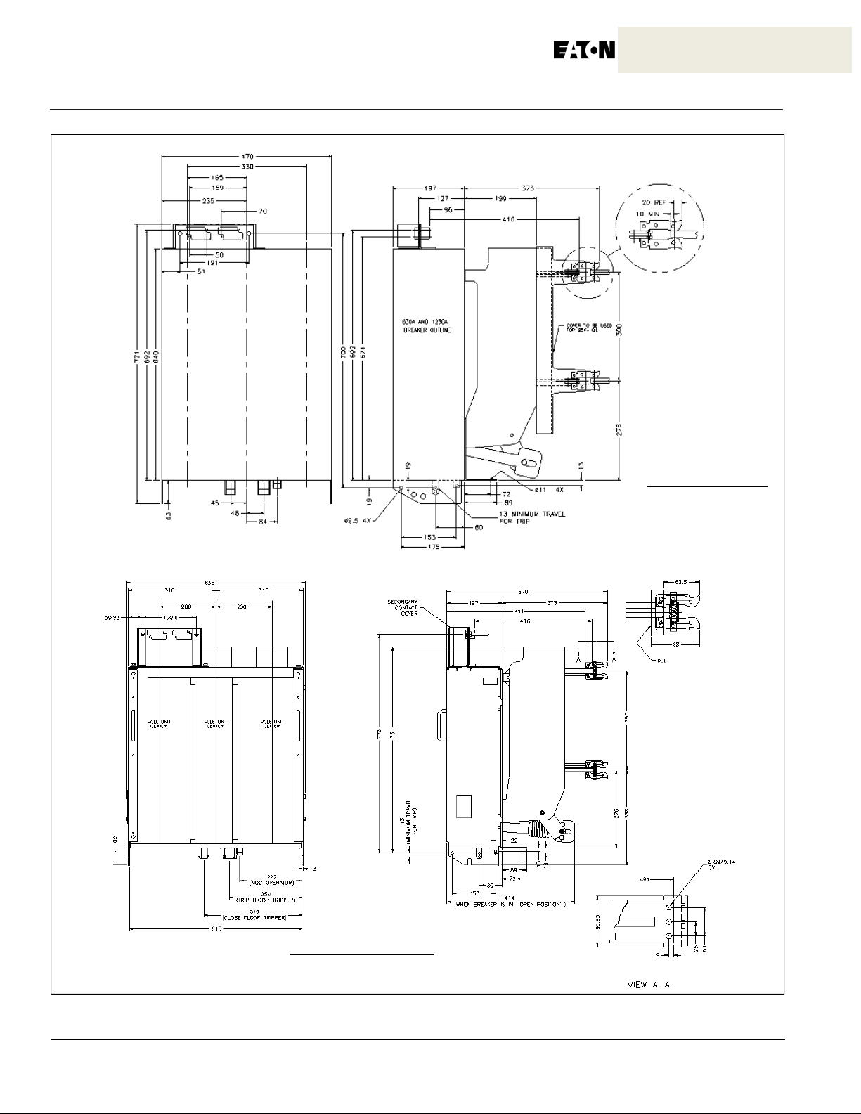
197
325
570
350
373
202
33.3
A
G
F
F
B
“A” POLE
“B” POLE
“C” POLE
C
1160
795.7
520
480
Rating
Up to 15 kV/Up to 1250A to 40kA
Up to 15 kV/1600A and2000A/Up to 40 kA
33.3
197
Earthing Contacts
A
B
C
D
E
F
570 300 1226 1202 1340 165 470 29
719 350 1299 1275 1340 200 620 33
570
373
202
C
E
720
B
80
Earthing Contacts
440
Rating
Up to 15 kV/Up to 1250A to 40kA
701
490 300 786 762 738 165 470 23
Up to 15 kV/1600A and2000A/Up to 40 kA
A
640 350 856 835 736 200 620 25
355.7
B
C
D E
F
19.34
269
“A” POLE
44.6
G
9.5
G
F
A
G
“C” POLE
“B” POLE
84.4
456.6
538
Weight Carriage
Weight Carriage
F
228.3
48.3
E
D
D
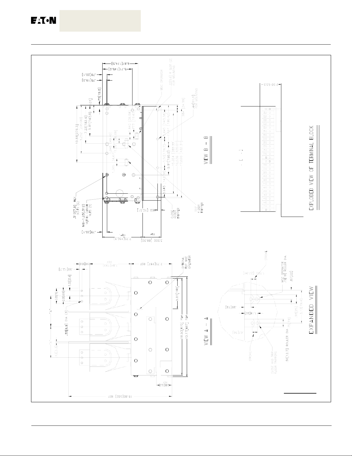
Figure 1-9 Outline and Dimensions (mm) Type W-VAC breaker element with carriage assembly and cradl e assem bly
Page11
IB131009EN
InstructionBook
Page 12
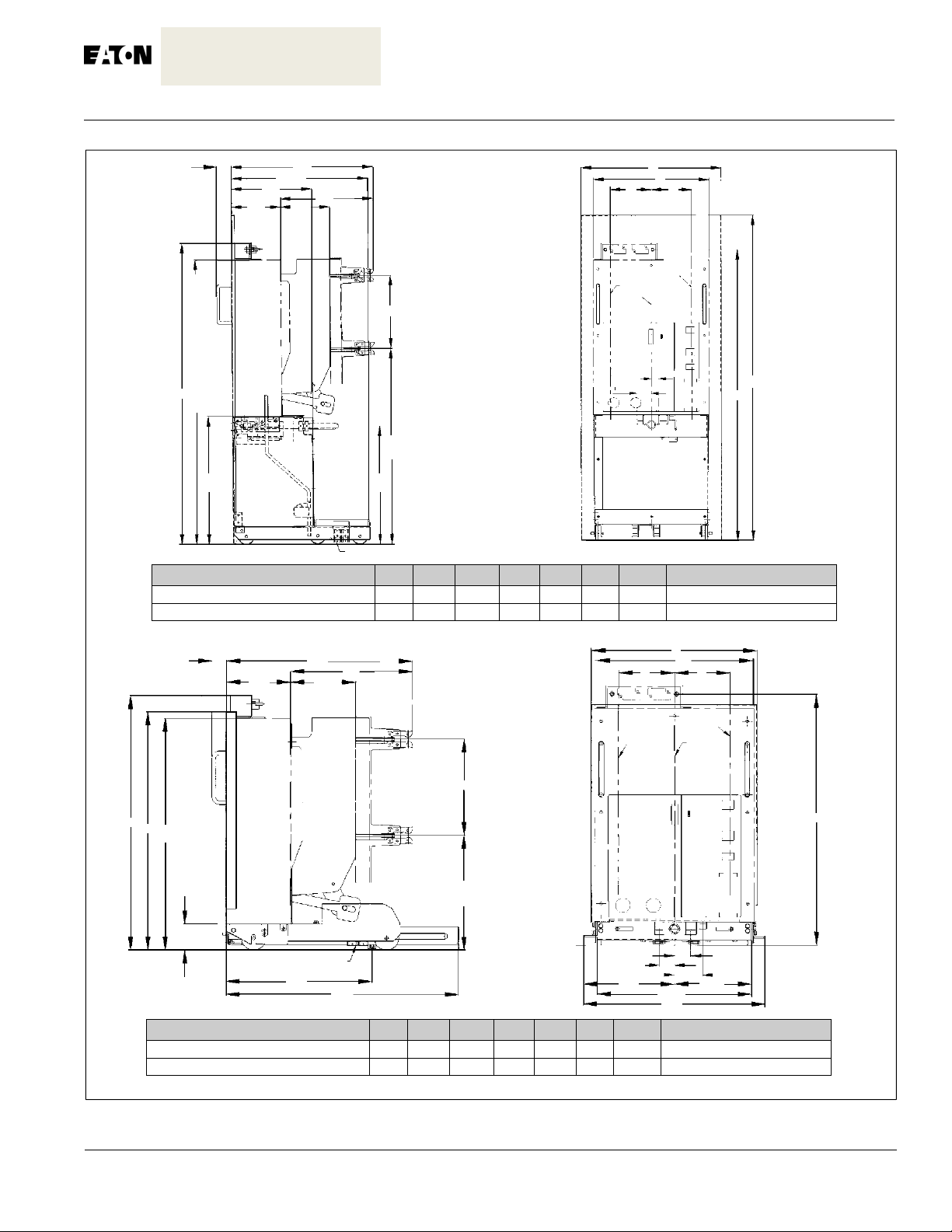
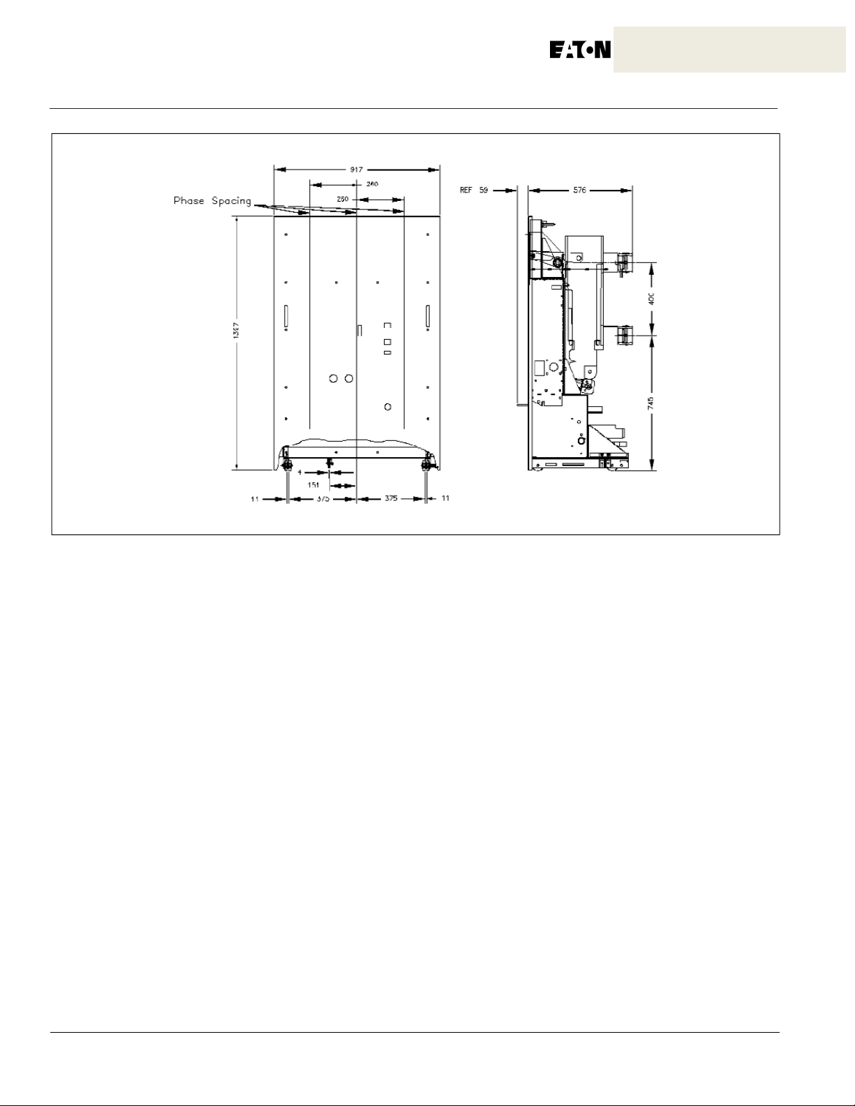
Figure 1-10 Outline and Dimensions (mm) Type W-VAC 3150 breaker with carriage a ssembl y
IB131009EN
Instruction Book
Page13
SECTION 2: SAFE PRACTICES
W-VAC, W-VACR, and W-VACW breakers are
equipped with high speed, high energy operating mechanisms. They are designed with several built-in interlocks and safety features to provide safe and proper
operating sequences.
closing springs charged. The closing spring should be
WARNING
TO PROTECT THE PERSONNEL ASSOCIATED WITH
INSTALLATION, OPERATION, AND MAINTENANCE
OF THESE BREAKERS, THE FOLLOWING PRACTICES MUST BE FOLLOWED:
• Only qualified persons, as defined in the local electrical code who are familiar with the installation and maintenance of medium voltage circuits and equipment,
should be permitted to work on these breakers.
• Read these instructions carefully before attempting
any installation, operation or maintenance of these
breakers.
• Always remove the removable breakers from their
enclosures or disconnect the fixed primary connections
associated with fixed breakers before performing any
maintenance. Failure to do so could result in electrical
shock leading to death, severe personal injury or property damage.
• Do not work on a breaker with the secondary test coupler engaged or fixed secondary connections made.
Failure to disconnect the test coupler could result in an
electrical shock leading to death, personal injury or
property damage.
• Do not work on a closed breaker or a breaker with
discharged and the main contacts open before working
on the breaker. Failure to do so could result in cutting or
crushing injuries.
• Do not use a drawout circuit breaker by itself as the
sole means of isolating a high voltage circuit, Remove
the breaker to the Disconnect position and follow good
lock-out and tagging rules, as well as all applicable
codes, regulations and work rules.
• Do not leave a drawout breaker in an intermediate
position in the cell. Always have the breaker either in the
Test or Connected position. Failure to do so could result
in a flash over and possible death, personal injury or
property damage.
• Always remove the maintenance tool from the breaker
after charging the closing springs.
• Circuit breaker elements are equipped with safety
interlocks. Do Not remove, interfere with or in any
manner defeat them. This may result in death, bodily
injury or equipment damage.
IB131009EN
 Loading...