

Eaton 3h.508, E5224C Series, 6-T-3H-508RPM-406 Operating Instructions Manual
For Sales and Support, Contact Walker EMD • Toll-free: (800) 876-4444 • Tel: (203) 426-7700 • Fax: (203) 426-7800 • www.walkeremd.com
Operating Instructions
LCD Hour Meter
E5224C Series
The E5224C Series are battery-powered LCD hour
meters. Typical elapsed timer applications include run
time, product life, cycle time, and time monitoring.
They are controlled by means of dry contacts or voltage
pulses.
DC models:
Timer: INP A: no function
INP B: Timer-Enable-Input
Main technical features:
Display: LCD, 8 decades, height of the figures 8 mm
[0.31 in.]
Display range:
0 – 99999999 with lead zero blanking.
Error: < 100 ppm
Overflow:
In case of a display range overflow, the timer
starts again from 0, but without removing the
leading zeros and activating all decimal
points.
Reset key: Requires rear terminal jumper to enable.
Housing: Panel mounting, 48 x 24 mm [1.89 x 0.94 in.]
according to DIN 43 700, RAL 7021
Panel cut-out:
22.2 x 45 mm [0.87 x 1.77 in.]
22.5 x 45.6 mm [0.89 x 1.80 in.] max.
Mounting depth:
approximately 48 mm [1.89 in.]
Weight: approximately 50 g [1.76 oz.]
Front panel rating:
IP65
AC/DC models:
Timer: INP A: Timer-Enable-Input AC/DC
INP B: reset input AC/DC
Connection:
Screw terminals, RM 5.00, 8 poles
Rated cross-section: 4.0 mm
2
solid wire
2.5 mm
2
stranded wire
AWG 12
Connection diameter:
0.4 – 2.3 mm
2
solid wire
AWG 28-12
EMC: Emissions per EN55011 Class B
Susceptibility per EN 61000-6-2
Low Voltage Directive (for the AC/DC models):
EN 61010 Part 1 ; overvoltage category 2,
pollution level 2
Power supply:
Non-replaceable lithium battery (lifetime
approximately 8 years at 20°C [68°F])
Working temperature:
-10 to +55°C [14 to 131°F], relative humidity
< 85%, non-condensing
Operating temperature:
-10 to +60°C [14 to 140°F]
Storage temperature:
-20 to +70°C [-4 to 158°F]
Backlighting:
must be powered by an external elecrical
source (24V ±20%, 50 mA)
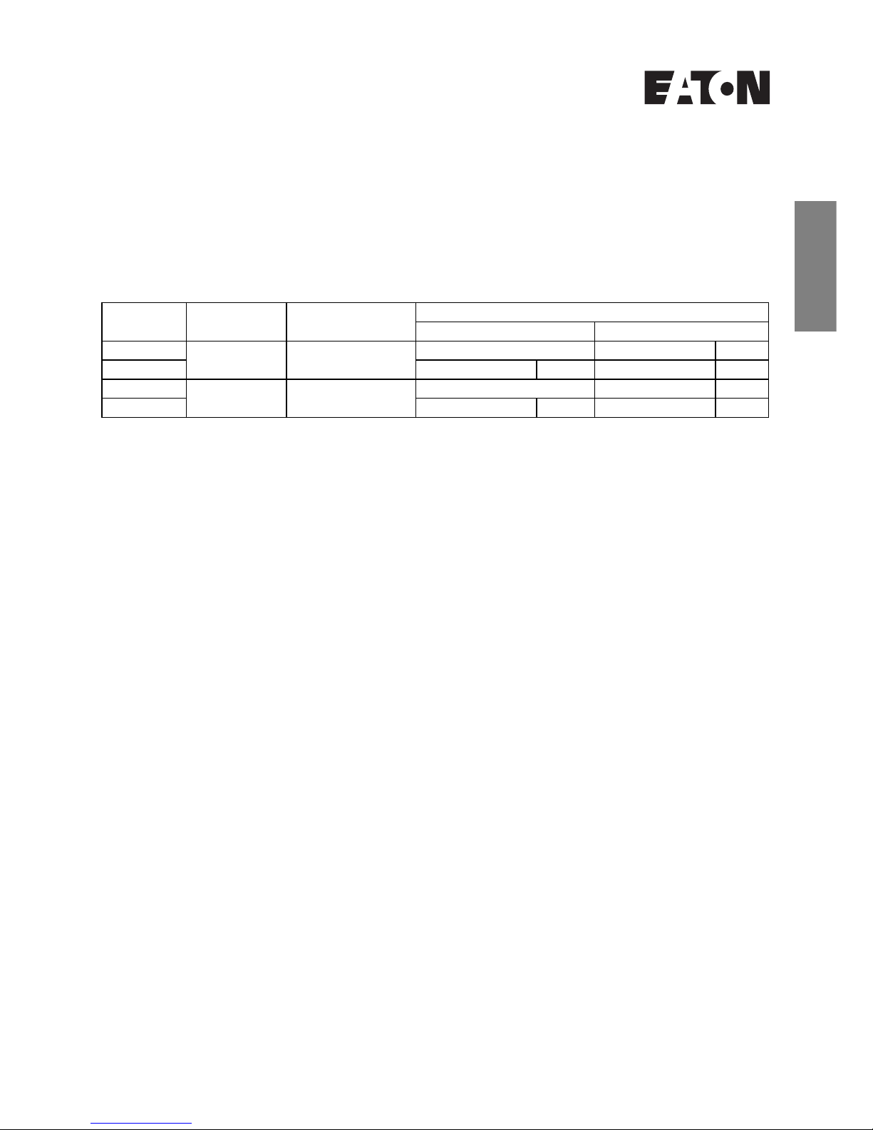
Table 1
Overview
Model Operating mode Time range Inputs
INP A INP B
E5224C0440 Timer 99999h 59 m/
99999.99 h
— 0 – 0.7V DC NPN
E52240C448 10 – 260V AC/DC AC/DC 10 – 260V AC/DC AC/DC
E5224C0450 Timer 9999 h 59 m 59 s/
9999999.9 s
— 0 – 0.7V DC NPN
E5224C0458 10 – 260V AC/DC AC/DC 10 – 260V AC/DC AC/DC
deutsch
français
español
english
MN05401006E 1
For Sales and Support, Contact Walker EMD • Toll-free: (800) 876-4444 • Tel: (203) 426-7700 • Fax: (203) 426-7800 • www.walkeremd.com
Screw terminal 1: no function
Screw terminal 2:
Timer Enable Input:
time measurement as long as the
input is active
NPN: active for low level
Input resistance: approximately 1 MOhm
Low level: 0 – 0.7V DC
High level: 3 – 30V DC
PNP: active for high level
Input resistance: approximately 100 kOhm
Low-level: 0 – 0.7V DC
High-level: 4 – 30V DC
Screw terminal 3:
Reset input:
active for negative edge contact
input / Open Collector NPN
Low level: 0 – 0.7V DC
High level: 3 – 30V DC
Min. pulse duration: 50 ms
Input resistance: approximately 2.2 MOhm
Screw terminal 4:
Reset key enable
Contact input / Open Collector NPN
Low level: 0 – 0.7V DC
High level: 3 – 5V DC
Input resistance: approximately. 2.2 MOhm
Input not active:
Reset key disabled
Input active (contact with GND):
Reset key enabled
Screw terminal
5:
Time range switching (Mode)
contact input / Open Collector NPN
Low level: 0 – 0.7V DC
High level: 3 – 5V DC
Input resistance: approximately. 2.2 MOhm
Function: see table 2
Remark
If the time range is changed during
operation,
the device must be reset.
Screw terminal
6:
Common GND connection
for all inputs
Screw terminal
7:
(–) external power supply for the backlight option
Screw terminal
8:
(+) external power supply for the backlight option
(24V DC ±20%, 50 mA)
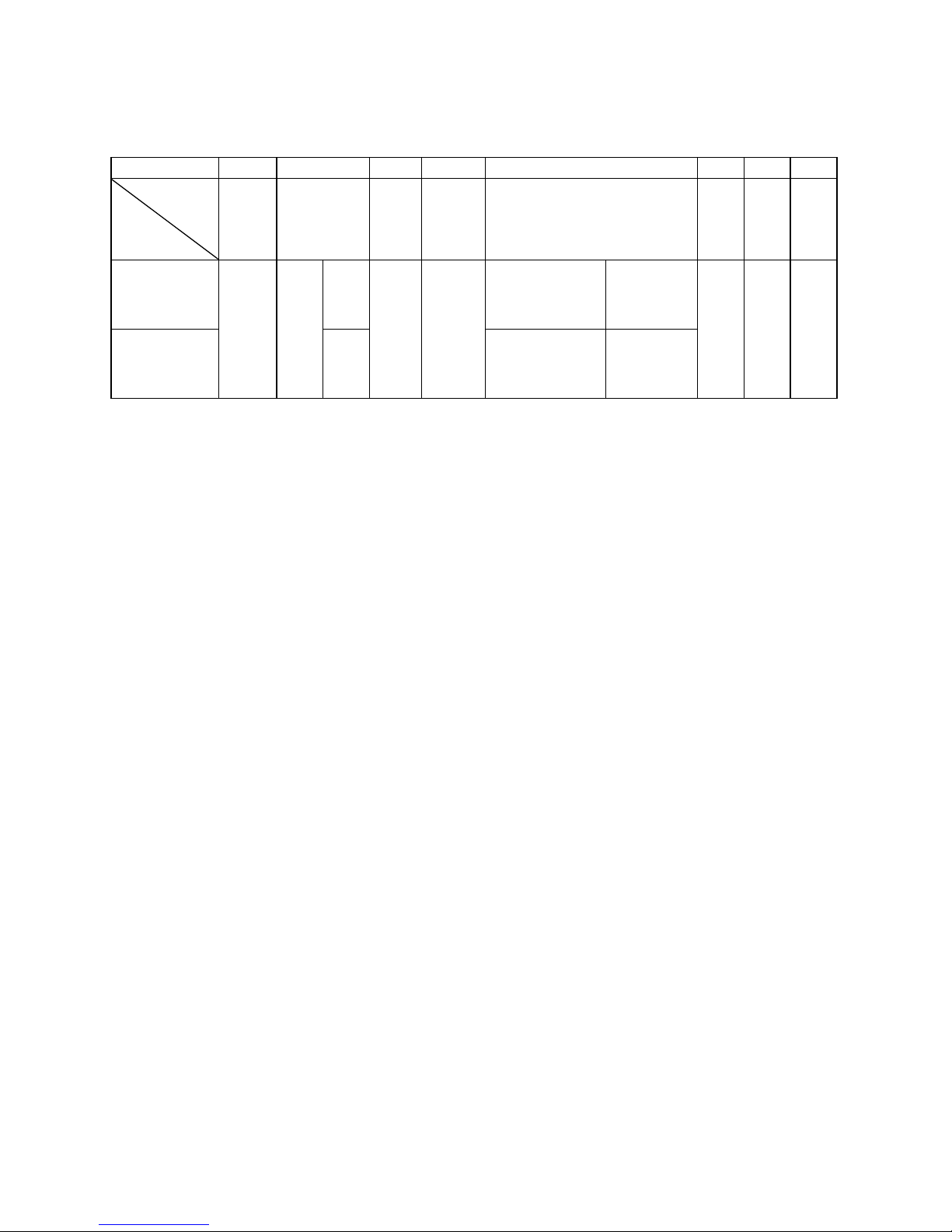
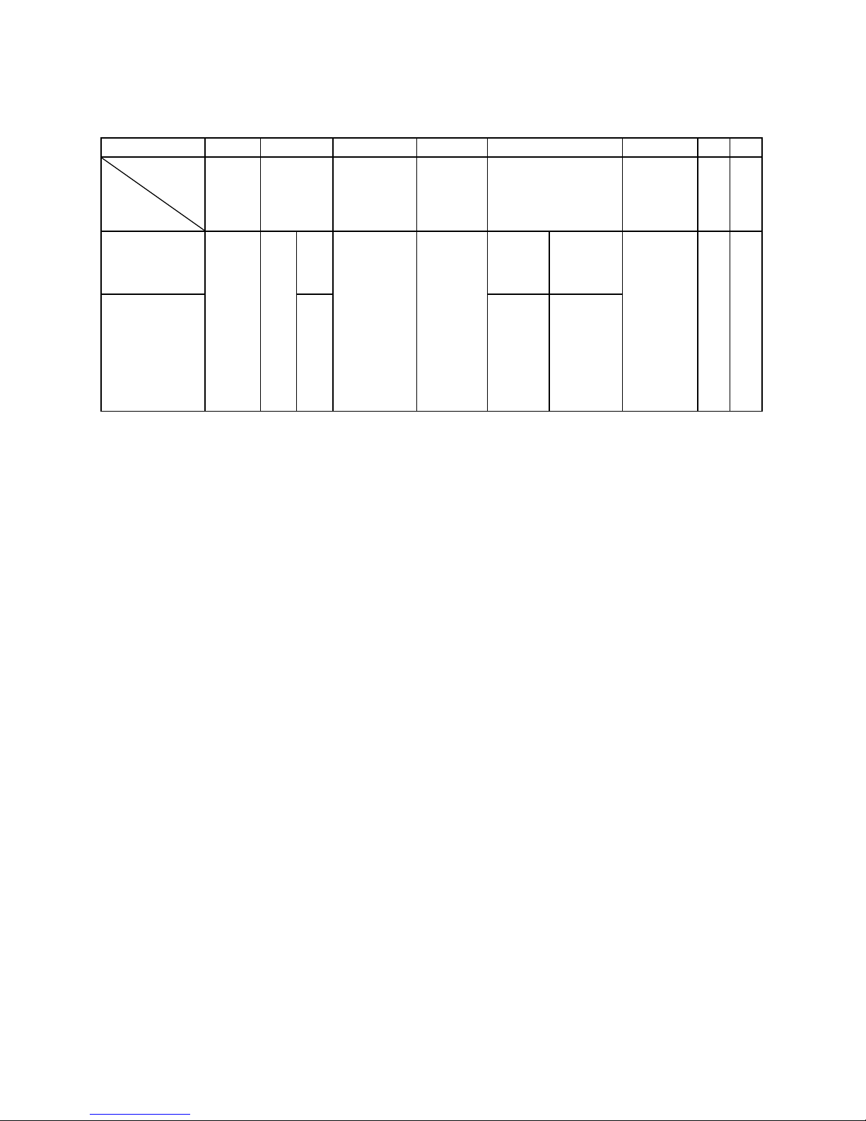
Table 2
2 MN05401006E
Input specifications, terminal assignment and adjustable time ranges (DC versions)
The time range is set via a control input (screw terminal 5).
Screw terminal No. 1 No. 2 No. 3 No. 4 No. 5 No. 6 No. 7 No. 8
Designation
Model
INP A INP B Reset Reset
Enable
Time range (Mode) GND BL–BL
+
E5224C0440
no function
Timer Enable Input
NPN
NPN reset input
Reset key enabled
when connected to
gnd.
open =
99999 h 59 m
contact with
GND =
99999.99 h
GND = 0V DC
Backlighting (–)
Backlighting (+)
E5224C0450 NPN
open =
9999 h 59 m 59 s
contact with
GND =
9999999.9 s
For Sales and Support, Contact Walker EMD • Toll-free: (800) 876-4444 • Tel: (203) 426-7700 • Fax: (203) 426-7800 • www.walkeremd.com
Screw terminal 1:
Timer Enable Input:
time measurement as long as the
level at this input is high.
Optocoupler input 10 – 260V AC/DC
galvanic isolation, active for High
signal
Low level: 0 – 2V AC/DC
High level: 10 – 260V AC/DC
Input resistance: approximately 160 kOhm
Screw terminal 2:
Common AC/DC, common connection for the
optocoupler inputs (screw terminals 1 and 3)
Screw terminal 3:
Reset input:
10 – 260V AC/DC galvanic
isolation
Min. pulse duration: 16 ms
Max. frequency: approximately 30 Hz
Low level: 0 – 2V AC/DC
High level: 10 – 260V AC/DC
Input resistance: approximately 160 kOhm
Screw terminal
4:
Reset key enable
Contact input / Open Collector NPN
Low level: 0 – 0.7V DC
High level: 3 – 5V DC
Input resistance: approximately
2.2 MOhm
Input not active: Reset key disabled
Input in contact with GND:
Reset key enabled
Screw terminal 5:
Time range switching (Mode)
Contact input / Open Collector NPN
Low level: 0 – 0.7V DC
High level: 3 – 5V DC
Input resistance: approximately 2.2 MOhm
Function: see table 3
Remark:
If the time range is changed during
operation,
the device must be reset.
Screw terminal 6:
Common GND connection for screw terminal 4
(reset key locking input) and screw terminal 5
(time range switching).
Screw terminal 7:
(–) external power supply for the backlight option
Screw terminal 8:
(+) external power supply for the backlight option
(24V DC ±20%, 50 mA)
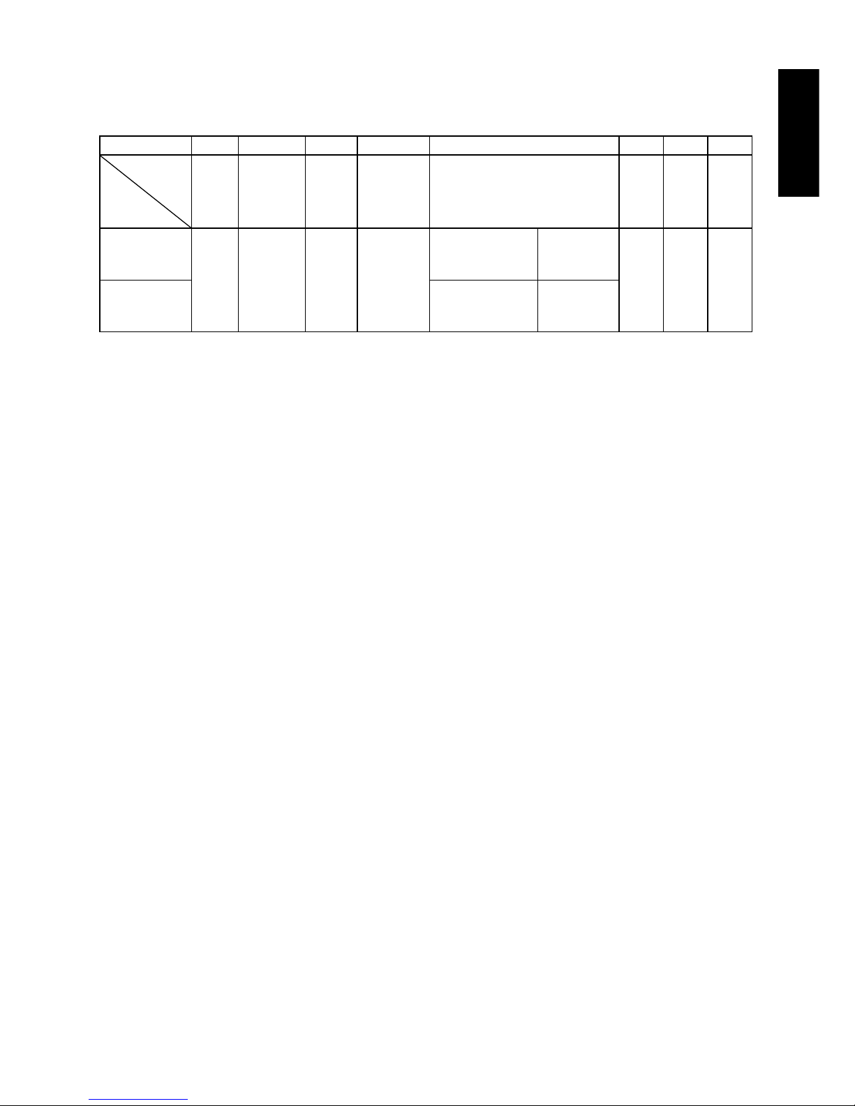
Table 3
english
MN05401006E 3
Input specification, terminal assignment and adjustable time ranges (AC/DC versions)
The time range is set via a control input (screw terminal 5).
Screw terminal No. 1 No. 2 No. 3 No. 4 No. 5 No. 6 No. 7 No. 8
Designation
Model
INP A
AC/DC
Common
AC/DC
INP B
AC/DC
Reset
Enable
Time range (Mode) GND BL
–
BL
+
E5224C0448
Timer Enable
Input AC/DC
Common
connection for
INP A and INP B
reset input
AC/DC
NPN reset key
locking input,
Contact with
GND. key free.
not active =
99999 h 59 m
contact with
GND =
99999.99 h
GND = 0V DC
Backlighting (–)
Backlighting (+)
E5224C0458
not active =
9999 h 59 m 59 s
contact with
GND =
9999999.9 s
For Sales and Support, Contact Walker EMD • Toll-free: (800) 876-4444 • Tel: (203) 426-7700 • Fax: (203) 426-7800 • www.walkeremd.com
Contents:
Timer
Clamp
Front frame for screw mounting,
Panel cut-out 50 x 25 mm [1.97 x 0.98 in.]
Front frame for clamp mounting,
Panel cut-out 50 x 25 mm [1.97 x 0.98 in.]
Seal
Operating instructions
Installation:
DC versions:
Use shielded wires for the counting and control inputs to
obtain the maximum EMC resistance.
Use according to the intended purpose:
This device may only be used inside as a panelmounted device! Applications of this product may be
found in industrial processes and controls in the branch
of the manufacturing lines for the metal, wood, plastics,
paper, glass, textile, etc., processing industries. It must
be considered that the overvoltages at the terminals of
the device must be limited to the values of overvoltage
category II. Overvoltage category II is described in the
standard EN 61 010 Part 1.
This device shall only operate when it has been
correctly mounted in a panel. It may only be used in
accordance with the chapter “Main technical features”.
This device shall not be used:
– in areas with risks of explosion,
– in the branches expressly quoted in the standard
EN 61 010.
If this device is used to monitor machines or a process
in which, in case of a failure of the device, there might
be risks of damaging the machine or causing accidents
to the operators, it is up to you to take appropriate
safety measures.
Note:
This product includes a lithium battery. Do not
open it by force, do not throw it in the fire.
Avoid temperatures below -20°C [-4°F] and
above 70°C [158°F]!
AC/DC versions:
Use shielded wires for the counting and control inputs to
obtain the maximum EMC resistance.
Safety instructions:
Only use these counters
– according to their intended
purpose
– if their technical condition is
perfect
– adhering to the operating
instructions and the general
safety instructions.
Also take into account the fact that there may exist user
or country-specific safety regulations, which must also
be followed.
!
4 MN05401006E
For Sales and Support, Contact Walker EMD • Toll-free: (800) 876-4444 • Tel: (203) 426-7700 • Fax: (203) 426-7800 • www.walkeremd.com
español
MN05401006E 5
Instrucciones de operación
Contadores con pantalla LCD
Serie E5224C
Los contadores con pantalla LCD de la serie E5224C
funcionan a baterías. Las aplicaciones típicas del
contador de tiempo transcurrido incluyen tiempo de
ejecución, vida útil del producto, tiempo de ciclo y
control de tiempo.
Se controlan por medio de contactos secos o por
impulsos de voltaje.
Modelos CC:
Temporizador: ENT A: sin función
ENT B: Entrada de habilitación
de temporizador
Características técnicas principales:
Pantalla: LCD, 8 decimales, altura de cifras 8 mm
[0,31 pulg.]
Rango de pantalla:
0 – 99999999 con supresión de cero inicial.
Error: < 100 ppm
Exceso:
En caso de exceso del rango de pantalla, el
temporizador vuelve a comenzar desde 0,
pero sin quitar los ceros iniciales y activando
los puntos decimales.
Tecla de restablecimiento:
Para habilitar se requiere el puente de borne
posterior.
Cubierta: Montaje en panel, 48 x 24 mm [1,89 x
0,94 pulg.] según DIN 43 700, RAL 7021
Plantilla de recorte del panel:
22,2 x 45 mm [0,87 x 1,77 pulg.]
22,5 x 45,6 mm [0,89 x 1,80 pulg.] máx.
Profundidad de montaje:
48 mm aproximadamente [1,89 pulg.]
Peso: 50 g aproximadamente [1,76 oz.]
Clasificación del panel delantero:
IP65
Modelos CA/CC:
Temporizador: ENT A: Entrada de habilitación
de temporizador CA/CC
ENT B: Entrada de
restablecimiento
CA/CC
Conexión:
Bornes de tornillo, RM 5,00, 8 polos
Sección transversal
clasificada: 4,0 mm
2
cable simple
2,5 mm
2
cable trenzado
AWG 12
Diámetro de la
conexión: 0,4 – 2,3 mm
2
cable
simple
AWG28-12
EMC: Emisiones por EN55011 Clase B
susceptibilidad por EN 61000-6-2
Directiva de bajo voltaje (para los modelos CA/CC):
EN 61010 Parte 1; categoría de sobrevoltaje
2, nivel de contaminación 2
Suministro de energía:
Batería de litio no reemplazable (vida útil
aproximada de 8 años a 20º C [68° F])
Temperatura de trabajo:
-10 a +55° C [14 a 131° F], humedad
relativa < 85%, sin condensación
Temperatura de funcionamiento:
-10 a +60° C [14 a 140° F]
Temperatura de almacenamiento:
-20 a +70° C [-4 a 158° F]
Iluminación posterior:
Se debe alimentar por medio de una fuente
eléctrica externa (24 V ± 20%, 50 mA)
Tabla 1
Información general
Modelo Modo de
funcionamiento
Rango de tiempo Entradas
ENT A ENT B
E5224C0440 Temporizador 99999h 59 m/
99999,99 h
— 0 – 0,7 V CC NPN
E52240C448 10 – 260 V CA/CC CA/CC 10 – 260 V CA/CC CA/CC
E5224C0450 Temporizador 9999 h 59 m 59 seg./
9999999,9 seg.
— 0 – 0,7 V CC NPN
E5224C0458 10 – 260 V CA/CC CA/CC 10 – 260 V CA/CC CA/CC
For Sales and Support, Contact Walker EMD • Toll-free: (800) 876-4444 • Tel: (203) 426-7700 • Fax: (203) 426-7800 • www.walkeremd.com
6 MN05401006E
Borne de tornillo 1: Sin función
Borne de tornillo 2:
Entrada de habilitación del temporizador:
Medición del tiempo mientras
la entrada esté activa
NPN: Activo para nivel bajo
Resistencia de entrada: Aproximadamente 1 MOhm
Nivel bajo: 0 – 0,7 V CC
Nivel alto: 3 – 30 V CC
PNP: Activo para nivel alto
Resistencia de entrada: Aproximadamente 100 kOhm
Nivel bajo: 0 – 0,7 V CC
Nivel alto: 4 – 30 V CC
Borne de tornillo 3:
Entrada de restablecimiento:
Activo para entrada de
contacto de borde negativo/
NPN de toma de corriente
abierta
Nivel bajo: 0 – 0,7 V CC
Nivel alto: 3 – 30 V CC
Duración de impulso mín: 50 ms
Resistencia de entrada: Aproximadamente 2,2 MOhm
Borne de tornillo 4:
Habilitación de tecla de restablecimiento
Entrada de contacto/NPN de toma de corriente abierta
Nivel bajo: 0 – 0,7 V CC
Nivel alto: 3 – 5 V CC
Resistencia de entrada: Aproximadamente 2,2 MOhm
Entrada inactiva:
Tecla de restablecimiento
deshabilitada
Entrada activa (contacto a tierra):
Tecla de restablecimiento
habilitada
Borne de tornillo
5:
Conmutación de rango de tiempo (modo)
Entrada de contacto/NPN de toma de corriente abierta
Nivel bajo: 0 – 0,7 V CC
Nivel alto: 3 – 5 V CC
Resistencia de entrada: Aproximadamente 2,2 MOhm
Función: Consulte la Tabla 2
Observación
Si se cambia el rango de tiempo durante
la operación,
se debe restablecer el
dispositivo.
Borne de tornillo
6:
Conexión a tierra común
para todas las entradas
Borne de tornillo
7:
(–) suministro de energía para la opción de
iluminación posterior
Borne de tornillo
8:
(+) suministro de energía para la opción de
iluminación posterior
(24 V CC ±20%, 50 mA)
Tabla 2
Especificaciones de entrada, asignación de borne y rangos de tiempo ajustables (versiones de CC)
Se configura el rango de tiempo por medio de una entrada de control (borne de tornillo 5).
Borne de tornillo Nº 1 Nº 2 Nº 3 Nº 4 Nº 5 Nº 6 Nº 7 Nº 8
Designación
Modelo
ENT A ENT B Restable-
cimiento
Habilita-
ción del
restable-
cimiento
Rango de tiempo
(modo)
CONEXIÓN
A TIERRABL–BL+
E5224C0440
Sin función
Entrada de la habilitación
del temporizador
NPN
Entrada de
restablecimiento NPN
La tecla de restablecimiento
se habilita cuando está
conectada a tierra.
Abierto =
99999 h
59 m
Contacto a
tierra =
99999,99 h
CONEXIÓN A TIERRA =
0 V CC
Iluminación posterior (–)
Iluminación posterior (+)
E5224C0450 NPN
Abierto =
9999 h
59 m
59 seg.
Contacto a
tierra =
9999999,9
seg.
 Loading...