

Page 1

Eaton® Intelligent Power® Manager (IPM)
User’s Guide
Page 2

Eaton is a registered trademarks of Eaton Corporation or its subsidiaries and affiliates. Google Chrome is a
trademark of Google, Inc. HyperTerminal is a registered trademark of Hilgraeve. Linux is a registered
trademark of Linus Torvalds in the United States, other countries, or both. Microsoft, Internet Explorer, Vista,
and Windows are registered trademarks of Microsoft Corporation in the United States and other countries.
Mozilla and Firefox are registered trademarks of the Mozilla Foundation. National Electrical Code and NEC are
registered trademarks of National Fire Protection Association, Inc. Phillips is a registered trademark of Phillips
Screw Company. All other trademarks are property of their respective companies.
©Copyright 2013 Eaton Corporation, Raleigh NC, USA. All rights reserved. No part of this document may be
reproduced in any way without the express written approval of
Eaton Corporation.
Page 3

Class A EMC Statements
FCC Information
This equipment has been tested and found to comply with the limits for a Class A digital device, pursuant to
part 15 of the FCC Rules. These limits are designed to provide reasonable protection against harmful
interference when the equipment is operated in a commercial environment. This equipment generates, uses
and can radiate radio frequency energy and, if not installed and used in accordance with the instruction manual,
may cause harmful interference to radio communications. Operation of this equipment in a residential area is
likely to cause harmful interference in which case the user will be required to correct the interference at his own
expense.
ICES-003
This Class A Interference Causing Equipment meets all requirements of the Canadian Interference Causing
Equipment Regulations ICES-003.
Cet appareil numérique de la classe A respecte toutes les exigences du Règlement sur le matériel brouilleur du
Canada.
Eaton is not responsible for damage to this product resulting f
modification of the product, or other events outside the reasonable control of Eaton or not arising under normal
operating conditions.
rom accident, disaster, misuse, abuse, non-Eaton
1F61
I.T.E.
Page 4

Special Symbols
The following are examples of symbols used on the UPS or accessories to alert you to important information:
RISK OF ELECTRIC SHOCK - Observe the warning associated with the risk
of electric shock symbol.
CAUTION: REFER TO OPERATOR'S MANUAL - Refer to your operator's
manual for additional information, such as important operating and
maintenance instructions.
This symbol indicates that you should not discard waste electrical or
electronic equipment (WEEE) in the trash. For proper disposal, contact your
local recycling/reuse or hazardous waste center.
Page 5

Table of Contents
1 INTRODUCTION . . . . . . . . . . . . . . . . . . . . . . . . . . . . . . . . . . . . . . . . . . . . . . . . . . . . . . . . . . . . . . . . . . . . . . . . 1
2 INSTALLATION . . . . . . . . . . . . . . . . . . . . . . . . . . . . . . . . . . . . . . . . . . . . . . . . . . . . . . . . . . . . . . . . . . . . . . . . . 9
Compatibility . . . . . . . . . . . . . . . . . . . . . . . . . . . . . . . . . . . . . . . . . . . . . . . . . . . . . . . . . . . . . . . . . . . 2
Eaton Devices . . . . . . . . . . . . . . . . . . . . . . . . . . . . . . . . . . . . . . . . . . . . . . . . . . . . . . . . . . . . . . 2
Serial Line Devices . . . . . . . . . . . . . . . . . . . . . . . . . . . . . . . . . . . . . . . . . . . . . . . . . . . . . . . . . . 3
Other Network Devices. . . . . . . . . . . . . . . . . . . . . . . . . . . . . . . . . . . . . . . . . . . . . . . . . . . . . . . 4
Eaton IPP Management. . . . . . . . . . . . . . . . . . . . . . . . . . . . . . . . . . . . . . . . . . . . . . . . . . . . . . . . . . . 4
Performance Evaluations . . . . . . . . . . . . . . . . . . . . . . . . . . . . . . . . . . . . . . . . . . . . . . . . . . . . . . . . . . 4
Network Ports . . . . . . . . . . . . . . . . . . . . . . . . . . . . . . . . . . . . . . . . . . . . . . . . . . . . . . . . . . . . . . . . . . 5
Troubleshooting . . . . . . . . . . . . . . . . . . . . . . . . . . . . . . . . . . . . . . . . . . . . . . . . . . . . . . . . . . . . . . . . . 6
Terms. . . . . . . . . . . . . . . . . . . . . . . . . . . . . . . . . . . . . . . . . . . . . . . . . . . . . . . . . . . . . . . . . . . . . . . . . 6
Acknowledgements. . . . . . . . . . . . . . . . . . . . . . . . . . . . . . . . . . . . . . . . . . . . . . . . . . . . . . . . . . . . . . 6
Java Licensing . . . . . . . . . . . . . . . . . . . . . . . . . . . . . . . . . . . . . . . . . . . . . . . . . . . . . . . . . . . . . . 7
Installation Prerequisites . . . . . . . . . . . . . . . . . . . . . . . . . . . . . . . . . . . . . . . . . . . . . . . . . . . . . . . . . . 9
On the System Hosting Eaton IPM . . . . . . . . . . . . . . . . . . . . . . . . . . . . . . . . . . . . . . . . . . . . . . 9
On the System that Displays the Web-based GUI . . . . . . . . . . . . . . . . . . . . . . . . . . . . . . . . . . 9
JRE Prerequisites . . . . . . . . . . . . . . . . . . . . . . . . . . . . . . . . . . . . . . . . . . . . . . . . . . . . . . . . . . . 10
JRE Installation . . . . . . . . . . . . . . . . . . . . . . . . . . . . . . . . . . . . . . . . . . . . . . . . . . . . . . . . . . . . . 10
Quick Start Instructions . . . . . . . . . . . . . . . . . . . . . . . . . . . . . . . . . . . . . . . . . . . . . . . . . . . . . . . . . . . 10
Graphical Installation . . . . . . . . . . . . . . . . . . . . . . . . . . . . . . . . . . . . . . . . . . . . . . . . . . . . . . . . . 10
Configuration . . . . . . . . . . . . . . . . . . . . . . . . . . . . . . . . . . . . . . . . . . . . . . . . . . . . . . . . . . . . . . . 11
License Code. . . . . . . . . . . . . . . . . . . . . . . . . . . . . . . . . . . . . . . . . . . . . . . . . . . . . . . . . . . . . . . 13
Operation. . . . . . . . . . . . . . . . . . . . . . . . . . . . . . . . . . . . . . . . . . . . . . . . . . . . . . . . . . . . . . . . . . 13
Installation Result . . . . . . . . . . . . . . . . . . . . . . . . . . . . . . . . . . . . . . . . . . . . . . . . . . . . . . . . . . . 14
Uninstalling the Eaton IPM . . . . . . . . . . . . . . . . . . . . . . . . . . . . . . . . . . . . . . . . . . . . . . . . . . . . . . . . 15
Upgrading the Eaton IPM Product . . . . . . . . . . . . . . . . . . . . . . . . . . . . . . . . . . . . . . . . . . . . . . . . . . . 15
Installing/Uninstalling the Eaton IPM (Command Line) . . . . . . . . . . . . . . . . . . . . . . . . . . . . . . . . . . . 15
JRE Installation . . . . . . . . . . . . . . . . . . . . . . . . . . . . . . . . . . . . . . . . . . . . . . . . . . . . . . . . . . . . . . . . . 15
. . . . . . . . . . . . . . . . . . . . . . . . . . . . . . . . . . . . . . . . . . . . . . . . . . . . . . . . . . . . . . . . . . . . . . . . . . . . . . 15
3 CONFIGURATION . . . . . . . . . . . . . . . . . . . . . . . . . . . . . . . . . . . . . . . . . . . . . . . . . . . . . . . . . . . . . . . . . . . . . . . 17
Configure Nodes . . . . . . . . . . . . . . . . . . . . . . . . . . . . . . . . . . . . . . . . . . . . . . . . . . . . . . . . . . . . . . . . 17
Discover Nodes Connected on the Network . . . . . . . . . . . . . . . . . . . . . . . . . . . . . . . . . . . . . . . . . . . 17
Quick Scan . . . . . . . . . . . . . . . . . . . . . . . . . . . . . . . . . . . . . . . . . . . . . . . . . . . . . . . . . . . . . . . . 18
Range Scan . . . . . . . . . . . . . . . . . . . . . . . . . . . . . . . . . . . . . . . . . . . . . . . . . . . . . . . . . . . . . . . . 18
Address Scan . . . . . . . . . . . . . . . . . . . . . . . . . . . . . . . . . . . . . . . . . . . . . . . . . . . . . . . . . . . . . . 19
Scan Settings for Discovery . . . . . . . . . . . . . . . . . . . . . . . . . . . . . . . . . . . . . . . . . . . . . . . . . . .20
Change driver node . . . . . . . . . . . . . . . . . . . . . . . . . . . . . . . . . . . . . . . . . . . . . . . . . . . . . . . . . . 21
Configure Node Settings . . . . . . . . . . . . . . . . . . . . . . . . . . . . . . . . . . . . . . . . . . . . . . . . . . . . . . . . . . 22
Configure Actions . . . . . . . . . . . . . . . . . . . . . . . . . . . . . . . . . . . . . . . . . . . . . . . . . . . . . . . . . . . . . . . 23
E-mail Notification Actions . . . . . . . . . . . . . . . . . . . . . . . . . . . . . . . . . . . . . . . . . . . . . . . . . . . . 25
Execute Script/Program Actions . . . . . . . . . . . . . . . . . . . . . . . . . . . . . . . . . . . . . . . . . . . . . . . . 25
Alarm Box Notification Actions . . . . . . . . . . . . . . . . . . . . . . . . . . . . . . . . . . . . . . . . . . . . . . . . .26
Configure User Accounts. . . . . . . . . . . . . . . . . . . . . . . . . . . . . . . . . . . . . . . . . . . . . . . . . . . . . . . . . . 27
System Settings . . . . . . . . . . . . . . . . . . . . . . . . . . . . . . . . . . . . . . . . . . . . . . . . . . . . . . . . . . . . 29
Eaton Intelligent Power Manager (IPM) User’s Guide v1.40 P-164000289—Rev 2 i
Page 6

Table of Contents
Automatic Data Purge . . . . . . . . . . . . . . . . . . . . . . . . . . . . . . . . . . . . . . . . . . . . . . . . . . . . . . . . . . . . 30
Manage the Cisco UCS Manager Component. . . . . . . . . . . . . . . . . . . . . . . . . . . . . . . . . . . . . . . . . . 30
Enabling the Component. . . . . . . . . . . . . . . . . . . . . . . . . . . . . . . . . . . . . . . . . . . . . . . . . . . . . .30
Add the Component . . . . . . . . . . . . . . . . . . . . . . . . . . . . . . . . . . . . . . . . . . . . . . . . . . . . . . . . . 30
Remove the Component . . . . . . . . . . . . . . . . . . . . . . . . . . . . . . . . . . . . . . . . . . . . . . . . . . . . . . 32
Edit a Component . . . . . . . . . . . . . . . . . . . . . . . . . . . . . . . . . . . . . . . . . . . . . . . . . . . . . . . . . . . 33
Configure the Cisco UCS Manager Component . . . . . . . . . . . . . . . . . . . . . . . . . . . . . . . . . . . . . . . . 34
Difference Between “Present” and “Future” Options . . . . . . . . . . . . . . . . . . . . . . . . . . . . . . . 34
Power Capping Timer . . . . . . . . . . . . . . . . . . . . . . . . . . . . . . . . . . . . . . . . . . . . . . . . . . . . . . . . 34
Global Power Allocation Policy . . . . . . . . . . . . . . . . . . . . . . . . . . . . . . . . . . . . . . . . . . . . . . . . .35
Power Control Policy and Priority . . . . . . . . . . . . . . . . . . . . . . . . . . . . . . . . . . . . . . . . . . . . . . . 36
Power Budget . . . . . . . . . . . . . . . . . . . . . . . . . . . . . . . . . . . . . . . . . . . . . . . . . . . . . . . . . . . . . . 37
Common Errors and Notifications for the Cisco UCS Manager Component . . . . . . . . . . . . . . . . . . . 38
4 SUPERVISION . . . . . . . . . . . . . . . . . . . . . . . . . . . . . . . . . . . . . . . . . . . . . . . . . . . . . . . . . . . . . . . . . . . . . . . . . . 41
Access to the Monitoring Interface . . . . . . . . . . . . . . . . . . . . . . . . . . . . . . . . . . . . . . . . . . . . . . . . . . 41
Local Access . . . . . . . . . . . . . . . . . . . . . . . . . . . . . . . . . . . . . . . . . . . . . . . . . . . . . . . . . . . . . . . 41
Remote Access . . . . . . . . . . . . . . . . . . . . . . . . . . . . . . . . . . . . . . . . . . . . . . . . . . . . . . . . . . . . . 41
Node List View . . . . . . . . . . . . . . . . . . . . . . . . . . . . . . . . . . . . . . . . . . . . . . . . . . . . . . . . . . . . . . . . . 41
Flexible Panels View . . . . . . . . . . . . . . . . . . . . . . . . . . . . . . . . . . . . . . . . . . . . . . . . . . . . . . . . . . . . . 43
Information Panel . . . . . . . . . . . . . . . . . . . . . . . . . . . . . . . . . . . . . . . . . . . . . . . . . . . . . . . . . . . 43
Status Panel . . . . . . . . . . . . . . . . . . . . . . . . . . . . . . . . . . . . . . . . . . . . . . . . . . . . . . . . . . . . . . . 44
Outlets Panel. . . . . . . . . . . . . . . . . . . . . . . . . . . . . . . . . . . . . . . . . . . . . . . . . . . . . . . . . . . . . . . 45
Measures Panel. . . . . . . . . . . . . . . . . . . . . . . . . . . . . . . . . . . . . . . . . . . . . . . . . . . . . . . . . . . . . 46
Environment Panel . . . . . . . . . . . . . . . . . . . . . . . . . . . . . . . . . . . . . . . . . . . . . . . . . . . . . . . . . . 47
Graph Panel . . . . . . . . . . . . . . . . . . . . . . . . . . . . . . . . . . . . . . . . . . . . . . . . . . . . . . . . . . . . . . . . 47
Synoptic Panel. . . . . . . . . . . . . . . . . . . . . . . . . . . . . . . . . . . . . . . . . . . . . . . . . . . . . . . . . . . . . . 48
Power Source . . . . . . . . . . . . . . . . . . . . . . . . . . . . . . . . . . . . . . . . . . . . . . . . . . . . . . . . . . . . . . 50
Powered Applications . . . . . . . . . . . . . . . . . . . . . . . . . . . . . . . . . . . . . . . . . . . . . . . . . . . . . . . . 51
Events Panel . . . . . . . . . . . . . . . . . . . . . . . . . . . . . . . . . . . . . . . . . . . . . . . . . . . . . . . . . . . . . . . 51
Statistics Panel . . . . . . . . . . . . . . . . . . . . . . . . . . . . . . . . . . . . . . . . . . . . . . . . . . . . . . . . . . . . . 51
Power Components . . . . . . . . . . . . . . . . . . . . . . . . . . . . . . . . . . . . . . . . . . . . . . . . . . . . . . . . . 52
Subviews . . . . . . . . . . . . . . . . . . . . . . . . . . . . . . . . . . . . . . . . . . . . . . . . . . . . . . . . . . . . . . . . . . . . . . 52
Defining Sub-views . . . . . . . . . . . . . . . . . . . . . . . . . . . . . . . . . . . . . . . . . . . . . . . . . . . . . . . . . . 52
Sharing Sub-views. . . . . . . . . . . . . . . . . . . . . . . . . . . . . . . . . . . . . . . . . . . . . . . . . . . . . . . . . . . 55
Device Supervision . . . . . . . . . . . . . . . . . . . . . . . . . . . . . . . . . . . . . . . . . . . . . . . . . . . . . . . . . . . . . . 56
Map View. . . . . . . . . . . . . . . . . . . . . . . . . . . . . . . . . . . . . . . . . . . . . . . . . . . . . . . . . . . . . . . . . . . . . . 57
Create a Customized Map View . . . . . . . . . . . . . . . . . . . . . . . . . . . . . . . . . . . . . . . . . . . . . . . . 57
Map Examples. . . . . . . . . . . . . . . . . . . . . . . . . . . . . . . . . . . . . . . . . . . . . . . . . . . . . . . . . . . . . . 57
Events . . . . . . . . . . . . . . . . . . . . . . . . . . . . . . . . . . . . . . . . . . . . . . . . . . . . . . . . . . . . . . . . . . . . . . . . 60
List Representation . . . . . . . . . . . . . . . . . . . . . . . . . . . . . . . . . . . . . . . . . . . . . . . . . . . . . . . . . . 60
Calendar Representation . . . . . . . . . . . . . . . . . . . . . . . . . . . . . . . . . . . . . . . . . . . . . . . . . . . . . . 61
Node Events List . . . . . . . . . . . . . . . . . . . . . . . . . . . . . . . . . . . . . . . . . . . . . . . . . . . . . . . . . . . . 61
Launching the Device Web Interface . . . . . . . . . . . . . . . . . . . . . . . . . . . . . . . . . . . . . . . . . . . . . . . . 64
Node List Export to CSV File . . . . . . . . . . . . . . . . . . . . . . . . . . . . . . . . . . . . . . . . . . . . . . . . . . . . . . . 64
5 SHUTDOWN . . . . . . . . . . . . . . . . . . . . . . . . . . . . . . . . . . . . . . . . . . . . . . . . . . . . . . . . . . . . . . . . . . . . . . . . . . . 67
Shutdown Configuration . . . . . . . . . . . . . . . . . . . . . . . . . . . . . . . . . . . . . . . . . . . . . . . . . . . . . . . . . . 67
Shutdown Through Hibernate . . . . . . . . . . . . . . . . . . . . . . . . . . . . . . . . . . . . . . . . . . . . . . . . . . 68
Eaton Intelligent Power Manager (IPM) User’s Guide v1.40 P-164000289—Rev 2 ii
Page 7

Table of Contents
Power Source View . . . . . . . . . . . . . . . . . . . . . . . . . . . . . . . . . . . . . . . . . . . . . . . . . . . . . . . . . . . . . . 68
Shutdown Sequence . . . . . . . . . . . . . . . . . . . . . . . . . . . . . . . . . . . . . . . . . . . . . . . . . . . . . . . . . . . . . 69
6 ADVANCED MANAGEMENT . . . . . . . . . . . . . . . . . . . . . . . . . . . . . . . . . . . . . . . . . . . . . . . . . . . . . . . . . . . . . 71
Nodes Settings . . . . . . . . . . . . . . . . . . . . . . . . . . . . . . . . . . . . . . . . . . . . . . . . . . . . . . . . . . . . . . . . . 71
Single Node Configuration Display . . . . . . . . . . . . . . . . . . . . . . . . . . . . . . . . . . . . . . . . . . . . . . 71
Single Card Settings . . . . . . . . . . . . . . . . . . . . . . . . . . . . . . . . . . . . . . . . . . . . . . . . . . . . . . . . . 71
Multiple Card Configurations Synchronization. . . . . . . . . . . . . . . . . . . . . . . . . . . . . . . . . . . . . . 73
Nodes Upgrade . . . . . . . . . . . . . . . . . . . . . . . . . . . . . . . . . . . . . . . . . . . . . . . . . . . . . . . . . . . . . . . . . 74
Upload Device Firmware . . . . . . . . . . . . . . . . . . . . . . . . . . . . . . . . . . . . . . . . . . . . . . . . . . . . . .74
Upgrade Applications . . . . . . . . . . . . . . . . . . . . . . . . . . . . . . . . . . . . . . . . . . . . . . . . . . . . . . . . 75
7 VIRTUALIZATION . . . . . . . . . . . . . . . . . . . . . . . . . . . . . . . . . . . . . . . . . . . . . . . . . . . . . . . . . . . . . . . . . . . . . . . 77
Enabling the Infrastructure Connectors Module . . . . . . . . . . . . . . . . . . . . . . . . . . . . . . . . . . . . 77
Eaton Solutions for VMware . . . . . . . . . . . . . . . . . . . . . . . . . . . . . . . . . . . . . . . . . . . . . . . . . . . . . . . 79
Standalone Hypervisor and Local Solution . . . . . . . . . . . . . . . . . . . . . . . . . . . . . . . . . . . . . . . . 79
Multiple Hypervisor and Remote Solution. . . . . . . . . . . . . . . . . . . . . . . . . . . . . . . . . . . . . . . . . 80
VMware Site Recovery Manager . . . . . . . . . . . . . . . . . . . . . . . . . . . . . . . . . . . . . . . . . . . . . . . 84
VMware LoadShedding Package. . . . . . . . . . . . . . . . . . . . . . . . . . . . . . . . . . . . . . . . . . . . . . . . 85
Eaton Solutions for Microsoft . . . . . . . . . . . . . . . . . . . . . . . . . . . . . . . . . . . . . . . . . . . . . . . . . . . . . . 85
Standalone Hypervisor and Local Solution . . . . . . . . . . . . . . . . . . . . . . . . . . . . . . . . . . . . . . . . 85
Multiple Hypervisor and Remote Solution. . . . . . . . . . . . . . . . . . . . . . . . . . . . . . . . . . . . . . . . . 85
Eaton Solutions for Citrix . . . . . . . . . . . . . . . . . . . . . . . . . . . . . . . . . . . . . . . . . . . . . . . . . . . . . . . . . . 87
Standalone Hypervisor and Local Solution . . . . . . . . . . . . . . . . . . . . . . . . . . . . . . . . . . . . . . . . 87
Multiple Hypervisor and Remote Solution. . . . . . . . . . . . . . . . . . . . . . . . . . . . . . . . . . . . . . . . . 88
Eaton Solution for Red Hat . . . . . . . . . . . . . . . . . . . . . . . . . . . . . . . . . . . . . . . . . . . . . . . . . . . . . . . . 90
Eaton Solutions for OpenSource Xen . . . . . . . . . . . . . . . . . . . . . . . . . . . . . . . . . . . . . . . . . . . . . . . . 91
Standalone Hypervisor and Local Solution . . . . . . . . . . . . . . . . . . . . . . . . . . . . . . . . . . . . . . . . 91
Configuring Hypervisors . . . . . . . . . . . . . . . . . . . . . . . . . . . . . . . . . . . . . . . . . . . . . . . . . . . . . . . . . . 92
Configuring Maintenance and Shutdown . . . . . . . . . . . . . . . . . . . . . . . . . . . . . . . . . . . . . . . . . . . . . 93
No Eaton IPP on VM Host . . . . . . . . . . . . . . . . . . . . . . . . . . . . . . . . . . . . . . . . . . . . . . . . . . . . .93
Eaton IPP Running on the VMHost . . . . . . . . . . . . . . . . . . . . . . . . . . . . . . . . . . . . . . . . . . . . . . 94
8 REDUNDANCY . . . . . . . . . . . . . . . . . . . . . . . . . . . . . . . . . . . . . . . . . . . . . . . . . . . . . . . . . . . . . . . . . . . . . . . . . 97
Enabling Redundancy . . . . . . . . . . . . . . . . . . . . . . . . . . . . . . . . . . . . . . . . . . . . . . . . . . . . . . . . . . . . 97
Electrical Redundancy Schemas . . . . . . . . . . . . . . . . . . . . . . . . . . . . . . . . . . . . . . . . . . . . . . . . 97
Configuring Redundancy . . . . . . . . . . . . . . . . . . . . . . . . . . . . . . . . . . . . . . . . . . . . . . . . . . . . . . . . . . 98
Redundancy Views . . . . . . . . . . . . . . . . . . . . . . . . . . . . . . . . . . . . . . . . . . . . . . . . . . . . . . . . . . . . . . 100
Selection View in Node List . . . . . . . . . . . . . . . . . . . . . . . . . . . . . . . . . . . . . . . . . . . . . . . . . . .100
Composite Device in Power Source View. . . . . . . . . . . . . . . . . . . . . . . . . . . . . . . . . . . . . . . . . 101
Redundancy Use Cases. . . . . . . . . . . . . . . . . . . . . . . . . . . . . . . . . . . . . . . . . . . . . . . . . . . . . . . . . . . 102
Use Case #1 . . . . . . . . . . . . . . . . . . . . . . . . . . . . . . . . . . . . . . . . . . . . . . . . . . . . . . . . . . . . . . . 102
Use Case #2 . . . . . . . . . . . . . . . . . . . . . . . . . . . . . . . . . . . . . . . . . . . . . . . . . . . . . . . . . . . . . . . 103
Use Case #3 . . . . . . . . . . . . . . . . . . . . . . . . . . . . . . . . . . . . . . . . . . . . . . . . . . . . . . . . . . . . . . . 103
Use Case #4 . . . . . . . . . . . . . . . . . . . . . . . . . . . . . . . . . . . . . . . . . . . . . . . . . . . . . . . . . . . . . . . 104
Redundancy Advanced Behavior Example . . . . . . . . . . . . . . . . . . . . . . . . . . . . . . . . . . . . . . . . . . . . 105
Redundancy Alarm Management with Four Modules. . . . . . . . . . . . . . . . . . . . . . . . . . . . . . . . 105
Protection Alarm Management with Four Modules . . . . . . . . . . . . . . . . . . . . . . . . . . . . . . . . . 106
Redundancy Compatibility. . . . . . . . . . . . . . . . . . . . . . . . . . . . . . . . . . . . . . . . . . . . . . . . . . . . .106
Eaton Intelligent Power Manager (IPM) User’s Guide v1.40 P-164000289—Rev 2 iii
Page 8

Table of Contents
9 USER DRIVERS . . . . . . . . . . . . . . . . . . . . . . . . . . . . . . . . . . . . . . . . . . . . . . . . . . . . . . . . . . . . . . . . . . . . . . . . . 109
User Drivers Editor . . . . . . . . . . . . . . . . . . . . . . . . . . . . . . . . . . . . . . . . . . . . . . . . . . . . . . . . . . . . . . 109
User Drivers Page . . . . . . . . . . . . . . . . . . . . . . . . . . . . . . . . . . . . . . . . . . . . . . . . . . . . . . . . . . . 109
User Driver Editor Dialog. . . . . . . . . . . . . . . . . . . . . . . . . . . . . . . . . . . . . . . . . . . . . . . . . . . . . . 111
Rule Editor Dialog . . . . . . . . . . . . . . . . . . . . . . . . . . . . . . . . . . . . . . . . . . . . . . . . . . . . . . . . . . . 113
10 STORAGE . . . . . . . . . . . . . . . . . . . . . . . . . . . . . . . . . . . . . . . . . . . . . . . . . . . . . . . . . . . . . . . . . . . . . . . . . . . . . . 121
Enabling the Infrastructure Connectors Module . . . . . . . . . . . . . . . . . . . . . . . . . . . . . . . . . . . . . . . . 121
Configuration . . . . . . . . . . . . . . . . . . . . . . . . . . . . . . . . . . . . . . . . . . . . . . . . . . . . . . . . . . . . . . . . . . . 122
Shutdown . . . . . . . . . . . . . . . . . . . . . . . . . . . . . . . . . . . . . . . . . . . . . . . . . . . . . . . . . . . . . . . . . . . . . 123
11 EXTENDED FUNCTIONALITY . . . . . . . . . . . . . . . . . . . . . . . . . . . . . . . . . . . . . . . . . . . . . . . . . . . . . . . . . . . . . 125
Configuring the Eaton IPM vCenter Plugin and WebPlugin . . . . . . . . . . . . . . . . . . . . . . . . . . . . . . . . 125
Checking for vCenter Plug-in Registration. . . . . . . . . . . . . . . . . . . . . . . . . . . . . . . . . . . . . . . . . 125
Events and Alarms . . . . . . . . . . . . . . . . . . . . . . . . . . . . . . . . . . . . . . . . . . . . . . . . . . . . . . . . . . 126
Using Eaton IPM through vCenter . . . . . . . . . . . . . . . . . . . . . . . . . . . . . . . . . . . . . . . . . . . . . . 127
Using the WebPlugin through the vSphere Web Interface . . . . . . . . . . . . . . . . . . . . . . . . . . . . 127
Configuring XenCenter Plug-in. . . . . . . . . . . . . . . . . . . . . . . . . . . . . . . . . . . . . . . . . . . . . . . . . . . . . . 128
Prerequisites . . . . . . . . . . . . . . . . . . . . . . . . . . . . . . . . . . . . . . . . . . . . . . . . . . . . . . . . . . . . . . . 128
Check XenCenter Plug-in Installation . . . . . . . . . . . . . . . . . . . . . . . . . . . . . . . . . . . . . . . . . . . . 128
Using Eaton IPM through XenCenter . . . . . . . . . . . . . . . . . . . . . . . . . . . . . . . . . . . . . . . . . . . . 130
Configuring Maintenance Mode and vMotion with vCenter . . . . . . . . . . . . . . . . . . . . . . . . . . . . . . . 130
Prerequisites . . . . . . . . . . . . . . . . . . . . . . . . . . . . . . . . . . . . . . . . . . . . . . . . . . . . . . . . . . . . . . . 130
Introduction . . . . . . . . . . . . . . . . . . . . . . . . . . . . . . . . . . . . . . . . . . . . . . . . . . . . . . . . . . . . . . . . 130
Understanding Maintenance Mode. . . . . . . . . . . . . . . . . . . . . . . . . . . . . . . . . . . . . . . . . . . . . . 131
Configuring Maintenance Mode Behavior in vCenter . . . . . . . . . . . . . . . . . . . . . . . . . . . . . . . . 131
Configuration Test . . . . . . . . . . . . . . . . . . . . . . . . . . . . . . . . . . . . . . . . . . . . . . . . . . . . . . . . . . . 131
VMware vCenter High Availability . . . . . . . . . . . . . . . . . . . . . . . . . . . . . . . . . . . . . . . . . . . . . . . . . . . 131
Configuring Maintenance Mode and Live Migration with SCVMM . . . . . . . . . . . . . . . . . . . . . . . . . . 133
Maintenance Mode . . . . . . . . . . . . . . . . . . . . . . . . . . . . . . . . . . . . . . . . . . . . . . . . . . . . . . . . . . 133
Understanding Live Migration . . . . . . . . . . . . . . . . . . . . . . . . . . . . . . . . . . . . . . . . . . . . . . . . . . 133
Configuration Test . . . . . . . . . . . . . . . . . . . . . . . . . . . . . . . . . . . . . . . . . . . . . . . . . . . . . . . . . . . 133
VMware References . . . . . . . . . . . . . . . . . . . . . . . . . . . . . . . . . . . . . . . . . . . . . . . . . . . . . . . . . . . . . 133
Eaton and Virtualization . . . . . . . . . . . . . . . . . . . . . . . . . . . . . . . . . . . . . . . . . . . . . . . . . . . . . . . 133
VMware ESX Configuration. . . . . . . . . . . . . . . . . . . . . . . . . . . . . . . . . . . . . . . . . . . . . . . . . . . . 133
vCenter Server (VMware Supervisor) . . . . . . . . . . . . . . . . . . . . . . . . . . . . . . . . . . . . . . . . . . . . 134
vSphere SDK for Perl. . . . . . . . . . . . . . . . . . . . . . . . . . . . . . . . . . . . . . . . . . . . . . . . . . . . . . . . . 134
Microsoft Hyper-V References . . . . . . . . . . . . . . . . . . . . . . . . . . . . . . . . . . . . . . . . . . . . . . . . . . . . . 134
Eaton and Virtualization . . . . . . . . . . . . . . . . . . . . . . . . . . . . . . . . . . . . . . . . . . . . . . . . . . . . . . . 134
Microsoft TechNet Library. . . . . . . . . . . . . . . . . . . . . . . . . . . . . . . . . . . . . . . . . . . . . . . . . . . . . 134
About Maintenance Mode. . . . . . . . . . . . . . . . . . . . . . . . . . . . . . . . . . . . . . . . . . . . . . . . . . . . . 134
Requirements for Using Live Migration . . . . . . . . . . . . . . . . . . . . . . . . . . . . . . . . . . . . . . . . . . 134
VMware Icons and Diagrams . . . . . . . . . . . . . . . . . . . . . . . . . . . . . . . . . . . . . . . . . . . . . . . . . . 134
12 VIRTUAL APPLIANCE . . . . . . . . . . . . . . . . . . . . . . . . . . . . . . . . . . . . . . . . . . . . . . . . . . . . . . . . . . . . . . . . . . . 135
Prerequisites and Requirements . . . . . . . . . . . . . . . . . . . . . . . . . . . . . . . . . . . . . . . . . . . . . . . . . . . . 135
Minimum System Requirements . . . . . . . . . . . . . . . . . . . . . . . . . . . . . . . . . . . . . . . . . . . . . . . 135
Virtualization Platform Supported . . . . . . . . . . . . . . . . . . . . . . . . . . . . . . . . . . . . . . . . . . . . . . . 135
Free Version Limitation . . . . . . . . . . . . . . . . . . . . . . . . . . . . . . . . . . . . . . . . . . . . . . . . . . . . . . . 135
Eaton Intelligent Power Manager (IPM) User’s Guide v1.40 P-164000289—Rev 2 iv
Page 9

Table of Contents
Deploying a Virtual Appliance in VMware vSphere . . . . . . . . . . . . . . . . . . . . . . . . . . . . . . . . . . . . . . 135
Configuring a Virtual Appliance . . . . . . . . . . . . . . . . . . . . . . . . . . . . . . . . . . . . . . . . . . . . . . . . . . . . . 136
Setting Security for a Virtual Appliance . . . . . . . . . . . . . . . . . . . . . . . . . . . . . . . . . . . . . . . . . . . . . . . 137
Basic Firewall Configuration . . . . . . . . . . . . . . . . . . . . . . . . . . . . . . . . . . . . . . . . . . . . . . . . . . . 137
Advanced Firewall Configuration. . . . . . . . . . . . . . . . . . . . . . . . . . . . . . . . . . . . . . . . . . . . . . . . 137
To Start or Stop the Firewall . . . . . . . . . . . . . . . . . . . . . . . . . . . . . . . . . . . . . . . . . . . . . . . . . . . 138
Configuring IPM. . . . . . . . . . . . . . . . . . . . . . . . . . . . . . . . . . . . . . . . . . . . . . . . . . . . . . . . . . . . . . . . . 139
VMware Studio References. . . . . . . . . . . . . . . . . . . . . . . . . . . . . . . . . . . . . . . . . . . . . . . . . . . . . . . . 139
Virtual Appliance on VMware Website . . . . . . . . . . . . . . . . . . . . . . . . . . . . . . . . . . . . . . . . . . . 139
Firewall (lptables). . . . . . . . . . . . . . . . . . . . . . . . . . . . . . . . . . . . . . . . . . . . . . . . . . . . . . . . . . . . 139
13 SERVICE AND SUPPORT. . . . . . . . . . . . . . . . . . . . . . . . . . . . . . . . . . . . . . . . . . . . . . . . . . . . . . . . . . . . . . . . . 141
14 WARRANTY. . . . . . . . . . . . . . . . . . . . . . . . . . . . . . . . . . . . . . . . . . . . . . . . . . . . . . . . . . . . . . . . . . . . . . . . . . . . 143
Eaton Intelligent Power Manager (IPM) . . . . . . . . . . . . . . . . . . . . . . . . . . . . . . . . . . . . . . . . . . 143
Eaton Intelligent Power Manager (IPM) User’s Guide v1.40 P-164000289—Rev 2 v
Page 10
Chapter 1 Introduction
The Eaton® Intelligent Power® Manager (IPM) is a power environmental device supervision tool for IT
environments. The Eaton IPM delivers a global view across the network fr
Exceptionally versatile, the software is compatible with any device that supports a network interface, such as
environmental sensors, other manufacturer’s Power Distribution Unit (PDU) or Eaton Enclosure Power
Distribu
management table by groups, centralize alarms, and maintain events logs for preventive maintenance of the
entire installed equipment base.
The Eaton IPM provides the following:
l
l
l
l
l
l
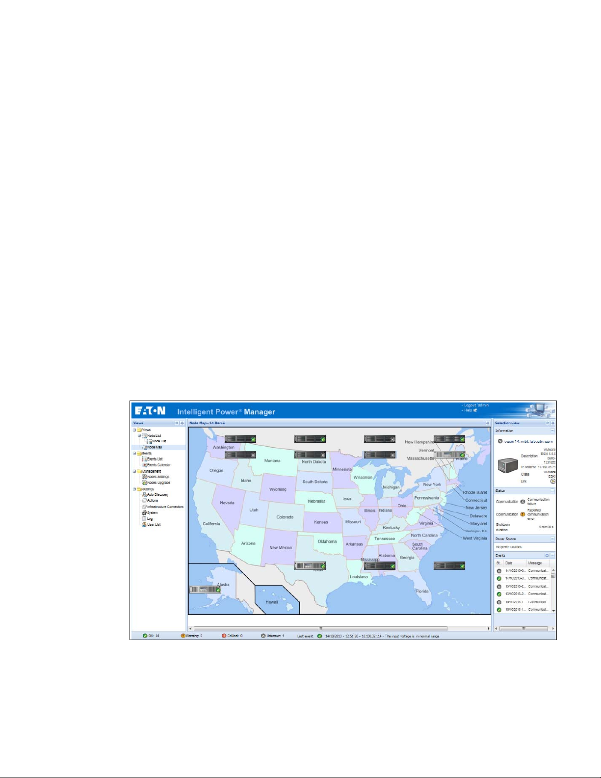
Figure 1 shows the Eaton IPM Node Map page.
tion Unit (ePDU®), other manufacturer’s UPSs, and applications. The Eaton IPM can also organize a
Discovers and supervises UPSs, PDUs, and ePDUs connected to the network either a card or a proxy. For
the detailed list of compatible solutions, see “Compatibility” on page 2.
Supervises the remote servers hosting the Eaton® Intelligent Power® Protectorr (IPP) or Network Shutdown
Module V3 application.
Provides advanced management feature (mass configuration and mass upload) with the Eaton® Network
Management Cards (also called NMC): Network-MS (example, 66102/103006826) and Modbus-MS
(example, 66103)
Provides local computer graceful shutdown through Network or local connectivity, such as USB or RS-232
port
Provides an agentless method for directly managing and controlling VMware® Hypervisors through the
®
VMware
vCenter™ management platform
Provides centralized management of Eaton IPP applications running on virtualized servers other than
VMware vCenter (such as Microsoft® Hyper-V™ Hypervisor or Citrix® Xen®).
om any PC with an Internet browser.
Figure 1. Eaton IPM Node Map Page
Eaton Intelligent Power Manager (IPM) User’s Guide v1.40 P-164000289—Rev 2 1
Page 11

Introduction
Compatibility
Eaton has tested the compatibility of the Eaton IPM with the following devices and applications.
NOTE If a device doesn’t support the Quick Scan feature, it can be supervised if Address
Scan or Range Scan operations are performed. See “Discover Nodes Connected on
the Network” on page 17 for more information.
Eaton Devices
Table 1. Eaton Devices
Eaton Equipment Designation Ty pe Features Protocols
XML SNMPV1 SNMPV3
See NOTE
Network Management Card Minislot SNMP
/
Web - Network-MS (ex 66102)
and associated Environment Sensor
See NOTE
Network Management Card & Modbus /
JBus -Modbus-MS (ex 66103) (through Ethernet
Network)
and associated Environment Sensor 66846
NOTE SNMP is available
for these devices, but IPM does not use it. IPM uses only XML protocol for this equipment.
ConnectUPS- Minislot Network Management Card
/ Network-M
S (ex 103006826)
ConnectUPS-BD Web /SNMP UPS Option Card
ConnectUPS-XSlot Web /SNMP/xHubCard (*) UPS Option Card
PXGX2000 (*) UPS Option Card
PXGX-UPS Card UPS Option Card
®
Eaton Advanced ePDU
(Europe = Switched (SW),
Advanced Monitored (AM) and Managed (MA) /
US= Advanced Monitored (AM) and Managed
(MA))
Eaton ePDU Monitored & Advanced Monitored PDU Integrated
Eaton ePDU Managed PDU Integrated
Eaton ePDU Switched PDU Integrated
MGE Switched PDU NM - 68130 / 68134/56132/
4/56136/56138
5613
MGE AmpMeter PDU NM - 68152/ 56134/56144
UPS Option Card
Eaton Pulsar
UPS Option Card
Eaton Pulsar
UPS Option Card
Eaton Powerware
Eaton Powerware
Eaton Powerware
Eaton Powerware
Eaton Powerware
ePDU Integrated
Communication Card
Communication Ca
Communication Ca
Communication Ca
PDU Integrated
Communication Card
Quick Scan (v 1.20)
Supervision (v. 1.20)
Management (v. 1.25)
rd
rd
rd
Quick Scan
• • •
Supervision
Manage
ment
Shutdown
Quick Scan
• • •
Supervision
Manage
ment
Shutdown
Quick Scan
— • •
Supervision
Management
Shutdown
Quick Scan
— • •
Supervision
Shutdown (*
Quick Scan
*)
— • •
Supervision
Shutdown (*
Quick Scan
*)
— • •
Supervision
Shutdown (*
Quick Scan
*)
— • •
Supervision
Shutdown
• — —
Supervision • — —
Supervision • — —
Supervision • — —
Supervision — • •
2 Eaton Intelligent Power Manager (IPM) User’s Guide v1.40 P-164000289—Rev 2
Page 12

Table 1. Eaton Devices (Continued)
Eaton Equipment Designation Ty p e Features Protocols
Computers (Windows - Linux) hosting the IPP
Shutdown C
MGE Network Management Proxy (Windows)
Computers (Windows) hosting the application
LanS
MGE Network Management Card Minislot SNMP/
and associated Environment Sensor
Network Management Card Transverse SNMP/
and associated Environment Sensor
ontroller
XML-Agent
afe Web View
Web - 66244
Web - 66074
Aphel 1 ePDU Integrated
Aphel 2 ePDU Integrated
UPS Proxy
(Shutdown Controller)
UPS Proxy (legacy) Supervision • — —
UPS Proxy (legacy) Supervision • — —
UPS Option Card (legacy) Supervision • — —
UPS Option Card (legacy) Supervision • — —
Communication Card
Communication Card
Quick Scan
Supervision
Management
Shutdown
Supervision — • •
Supervision — • —
Introduction
XML SNMPV1 SNMPV3
• — —
Serial Line Devices
The Eaton IPM is compatible with the following serial line devices (see Tabl e 2).
Table 2. Serial Line Devices
Eaton Equipment Designation Connectivity
Eaton 3105, 5110, 5115, 5130, 9130, 9135, 9140 and legacy 9120, 9125 USB or RS-232
Eaton BladeUPS, 5125, 9155, 9355, 9390, 9395 RS-232 only
Eaton Pulsar Series:
Evolution 650 / 850 / 1150 / S 1250 / 1550 / S 1750 / 2000 / S 2500 / S 3000
Pulsar 700 / 1000 / 1500 / 1000 RT2U / 1500 RT2U (Intl. & US Models)
Pulsar M / EX
Eaton 5P, 5PX
Pulsar MX & Pulsar MX Frame 16 U / MX
Eaton 9PX
Eaton Pulsar Series:
EX RT
Comet EX RT 1:1 / 3:1 / EX
NOTE Ellipse AS
supported by Personal Solution Pac software.
5 RT (Asia/Pacific)
R 600/750/1000/1500 USBS, Ellipse MAX, Protection Station, Protection Center, and NOVA AVR are currently
USB or RS-232
RS-232 only
Eaton Intelligent Power Manager (IPM) User’s Guide v1.40 P-164000289—Rev 2 3
Page 13

Introduction
Other Network Devices
The Eaton IPM is compatible with the following other network device (see Table 3).
Table 3. Other Devices
Eaton Equipment Designation Card Proxy Features
HP UPS Network Module Minislot (AF465A) Network Card Quick Scan
Dell Network UPS Card (H910P) Network Card Quick Scan
IBM UPS Network Management Card (46M4110) Network Card Quick Scan
All IETF MIB enabled UPSs (R
(Standard IETF UPS MIB 1.3.6.1.2.1.33.xx)
PowerDsine series 6000 Card —
Servertech sentry models PDU Integrated Communication Card —
l
NETAPP® (FAS2040 Series, i.e: FAS 2040)
l
HP (X1400 G2 Network Storage)
l
Synology® (RS812+)
l
NETGEAR® (ReadyNAS® 2100)
l
QNAPt® (TS-559)
l
BUFFALOt® (LinkStation™, TeraStation™)
Network UPS Tools (NUT) enabled devices Generic Driver Quick Scan
FC1628), such as Liebert
Storage
— Supervision
Generic Driver —
Supervision
Supervision
Supervision
Supervision
Eaton IPP Management
The Eaton IPP can be remotely managed, configured, and updated using Eaton IPM supervisory software.
Using the Eaton IPM, you can perform mass configurations and mass updates of Eaton IPP applications. The
Eaton IPM can also remotely perform the following:
l
Display an Eaton IPP configuration
l
Configure a single Eaton IPP
l
Synchronize multiple Eaton IPP configurations
l
Tr ig g e r Eaton IPP upgrade
Performance Evaluations
To provide a performance evaluation, Eaton has tested the following configurations:
Test with Machine 1 (server Dell PowerEdge 2900)
l
CPU: Intel® Xeon® 5130 dual-core @2GHz
l
Memory: 2Go DDR2 @666MHz
l
HDD: 2 HDDs 67GB 7200 rpm RAID 0 (Mirroring)
l
OS: Microsoft® Windows Server® 2008 64 bits
4 Eaton Intelligent Power Manager (IPM) User’s Guide v1.40 P-164000289—Rev 2
Page 14

Introduction
Test conditions during 40 hours:
l
1300 nodes (including ~50 real), mainly Eaton IPMs, and Network Management Cards.
l
Average CPU load: 20~30%
l
Memory load: 200~300MB
Test with Machine 2 (typical PC)
l
CPU: Intel Core™ 2 Duo 6600 @2.4GHz
l
Memory: 2Go DDR2
l
HDD: 1 HDD 220 GB 7200 rpm
l
OS: Microsoft® Windows Vista® Enterprise 32 bits
Test conditions during 40 hours:
l
1000 nodes (including ~50 real), mainly Eaton IPMs, and some NSM and Network Management Card.
l
Average CPU load: ~ 60%
l
Memory load: 200 ~300MB
NOTE These tests have been performed on Windows Server Operating System. The
Windows 2003 or 2008 Operating Systems do not have the limitation of 10
simultaneous connections.
Network Ports
Table 4 lists the network ports used by the Eaton IPM.
Table 4. Network Ports
Eaton Network
Management
Protocol Mode Port
Card
SMTP TCP/25 OUT OUT OUT OUT
DHCP/BOOTP UDP/67 OUT OUT X X
TFTP UDP/69 IN X OUT OUT
HTTP TCP/80 IN IN IN/OUT IN/OUT
NTP UDP/123 OUT OUT X X
SNMP UDP/161 IN IN OUT OUT
SNMP Traps UDP/162 OUT OUT X X
UNMP UDP/200 X OUT IN/OUT IN/OUT
HTTPS TCP/443 IN IN IN/OUT IN/OUT
Eaton Supervision TCP/4679 X X IN/OUT IN/OUT
Eaton Notification Broadcast UDP/4679 IN/OUT X IN/OUT IN/OUT
Eaton SSL Supervision TCP/4680 X X IN/OUT IN/OUT
Eaton Alarms Broadcast UDP/4680 OUT X IN IN
Eaton Connected Alarms TCP/5000 IN X OUT OUT
Eaton Connected Alarms TCP/5001 X X IN OUT
IPP-Unix (NUT) TCP/3493 X X IN/OUT IN/OUT
NOTE PXG
X2000, PXGX-UPS, Connect UPS BD, Connect UPS X-Slot, Network-MS
Other Eaton UPS
Management Cards
*NOTE
Eaton IPP with
Shutdown Controller
Eaton IPP and Eaton
IPM
Eaton Intelligent Power Manager (IPM) User’s Guide v1.40 P-164000289—Rev 2 5
Page 15

Introduction
Troubleshooting
Term s
HTML pages
Cannot display the UPS properties page. HTTP 404 error with IE.
Solution:
Check the URL entered.
https://<name or IP of the computer hosting Eaton IPM>:4680/
- or -
http://<name or IP of the computer hosting Eaton IPM>:4679/
This section provides related terms and definitions.
IP Address
When Transmission Control Protocol / Internet Protocol (TCP/IP) is installed on a computer, an Internet Protocol
(IP) address is assigned to the system. Each address is unique and is made up of four numbers, each between
0 and 255, such as168.8.156.210.
OSGi
OSGi is a module system and service platform for the Java programming language that implements a complete
and dynamic component model.
Secure Socket Layer
The Secure Socket Layer (SSL) is a solution for securing transactions over the internet. SSL is a communication
protocol that authenticates the data exchanged, as well as ensuring its confidentiality and integrity. The protocol
uses a recognized encryption method, the RSA algorithm with a public key. SSL is built into Internet Web
browsers. The padlock in the bottom of your browser screen automatically displays if the server sending
information uses SSL.
Transmission Control Protocol / Internet Protocol
TCP/IP is a family of network and communication protocols for the transport and network layers. Also known
as the Internet Protocol suite of network communication protocols.
Acknowledgements
The Eaton software development team is grateful to the following projects:
l
Spider Monkey
l
Ext JS
l
SQLite
- The SQLite Project (http://www.sqlite.org/) generously donated source code to the public domain that
l
Open SSL
-This Eaton IPM product includes software developed by the OpenSSL Project for use in the OpenSSL
-This Eaton IPM product includes cryptographic software written by Eric Young (eay@cryptsoft.com).
-This Eaton IPM product includes software written by Tim Hudson (tjh@cryptsoft.com).
helped us for this project.
Toolkit (http://www.openssl.org/).
6 Eaton Intelligent Power Manager (IPM) User’s Guide v1.40 P-164000289—Rev 2
Page 16

Introduction
!
IMPORTANT
l
Lib USB
l
Net SNMP
The full license version for each of these projects is available from Eaton IPM using the
Settings > System > About selection path.
Java Licensing
Eaton's advanced software (infra connector) uses the OSGI framework technology. All the constituent modules
of the new features (virtualization, storage, Cisco UCS) are based on OpenJDK (Open Java Development Kit,
which is a free and open source implementation of the Java Platform).
A Java Runtime Environment (JRE) must be installed on the target machine to use these features. This one can
be open source, such as OpenJRE, or business, such as Oracle.
Acceptance of licenses, related to Java Runtime Environment, is the responsibility of the end user.
Eaton Intelligent Power Manager (IPM) User’s Guide v1.40 P-164000289—Rev 2 7
Page 17

Introduction
8 Eaton Intelligent Power Manager (IPM) User’s Guide v1.40 P-164000289—Rev 2
Page 18

Chapter 2 Installation
This chapter provides Eaton Intelligent Power Manager (IPM) installation prerequisites and quick start
installation procedures
NOTE Please refer to the following installation information for operating system
Installation Prerequisites
This section provides installation prerequisites for the following:
l
Systems hosting the Eaton IPM
l
Systems that display the Web-based graphical user interface (GUI)
On the System Hosting Eaton IPM
The Eaton IPM can be installed on
Vista® 7,
and 2012.
l
l
Microsoft® Windows 7 and 8, and on
For better performances with multiple nodes, Eaton recommends a Microsoft® Windows Server® OS (that
does not have the limitation of 10 simultaneous network connections)
To avoid network or serial port access conflicts, do not install the Eaton IPM on a machine that also hosts:
- Network management system, such as HP OpenView
- Eaton Intelligent Power Protector (IPP)
- Eaton Enterprise Power Manager
- Eaton Network Shutdown Module
- Network Management Proxy
- Eaton UPS Management Software
. Procedures for uninstalling and upgrading the product are also included.
compatibility:
http://pqsoftware.eaton.com/install/common/eaton_
Microsoft® Windows 2000,
Microsoft® Windows XP®,
os_compatibilities_aa.pdf
Microsoft® Windows Server® 2003, 2008 (including R2 revision),
®
or CA Unicenter
®
Microsoft® Windows
NOTE This is the previous Eaton software for managing UPSs. If you were using it
previously, remove it before installing the new Eaton IPM software.
On the System that Displays the Web-based GUI
The
Eaton IPM
interface can be secured through Secure Socket Layer (SSL) connection and is also secured through login and
password.
Eaton IPM
The
l
Google® Chrome™
l
Mozilla Firefox®
l
Microsoft® Internet Explorer® (IE) version 7 and later
graphical interface can be accessed remotely using a simple Web browser. Access to this
graphical interface has been tested with:
NOTE For optimal performance, Google Chrome or Firefox is recommended. For good
performance, IE version 9 and later is recommended. IE6 performance is not
optimal.
Eaton Intelligent Power Manager (IPM) User’s Guide v1.40 P-164000289—Rev 2 9
Page 19

Installation
JRE Prerequisites
For all features correlated to the infrastructure connector (like VMware, UCS, NetApp) a JRE must be installed
on the system hosting Eaton IPM (see “JRE Installation” on page 15). If this prerequisite is not installed, only
ualization features are available, such as the legacy API for VMware connectors.
virt
Citrix XenCenter
Virtualization,
Table 5. JRE Virtualization, Storage, and Server
Software No JRE installed JRE 1.6 or greater
Storage, or Server
Virtualization New Vmware vCenter — •
New Vmware ESX/ESXi — •
Microsoft SCVMM •
Citrix XenCenter • •
Citrix XenServer • •
Vmware vCenter (legacy API) • •
Vmware ESX/ESXi (legacy API) • •
Storage NetApp Storage — •
Server Cisco UCS Manager — •
NOTE On
ly available if the system hosting is based on Microsoft operating system. See “Eaton Solutions for Microsoft” on page 85.
see NOTE
JRE Installation
The installation of the Java Runtime Environment (JRE) is Operating System platform-dependent. All new Eaton
components have been developed and tested for the Java version 1.6 or later. After installing the correct JRE,
the IPM must be reloaded, to take account this new environment.
Quick Start Instructions
This section includes quick start installation and configuration instructions.
•
see NOTE
Graphical Installation
To install the
1. On a computer with a Windows OS, run the Eaton Intelligent Power Manager package under an
administrator account. A Web browser displays the Eaton Intelligent Power Manager Installer Welcome
screen.
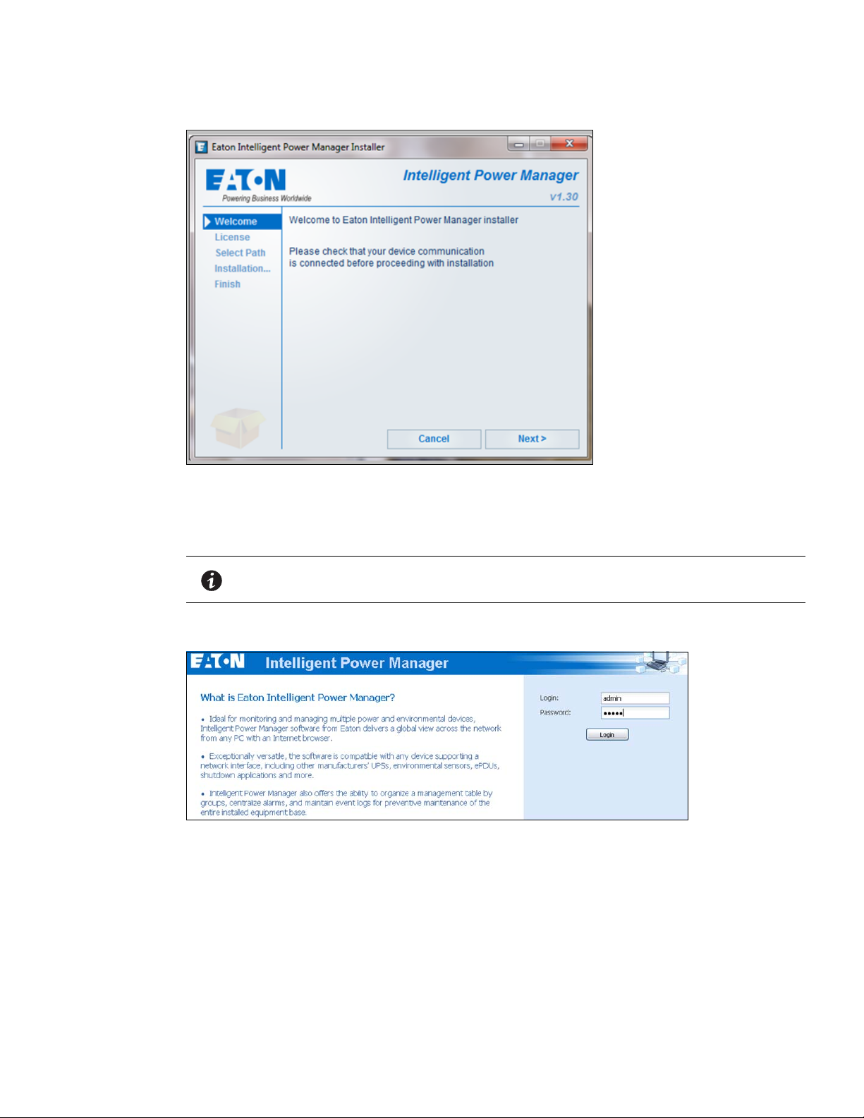
2. Observe the prompt and verify that the communication device is connected. Click Nex
The Login screen displays.
Eaton IPM
:
t (see Figure 2).
10 Eaton Intelligent Power Manager (IPM) User’s Guide v1.40 P-164000289—Rev 2
Page 20
Installation
Figure 2. Welcome Screen
3. Read the application description. Type the login and password and click Login (se
e Figure 3).
NOTE The default entry for login and password is admin.
Figure 3. Login Screen
Configuration
When started, the application automatically performs a discovery using the “Quick Scan” option:
l
Using the “Quick Scan” operation, you will discover the following through broadcast: Network Management
Cards Network-MS (ex 66102 / 103006826) and Modbus-MS (ex 66103), PXGX2000, PXGX-UPS,
ConnectUPS BD, ConnectUPS X, ConnectUPS MS, Intelligent Power Protector, Network Shutdown Module
V3, new Eaton ePDU, new HP UPS Card, new Dell UPS Card, or new IBM UPS Card.
l
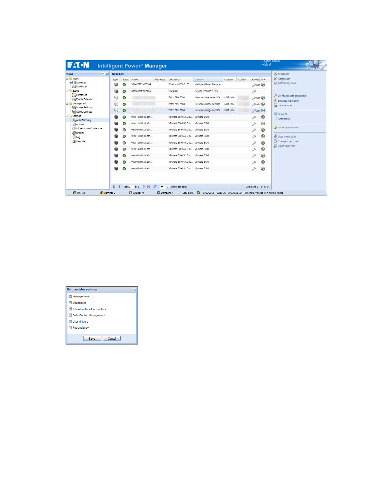
Display the discovered nodes using Settings > Auto Discovery (see Figure 4).
Eaton Intelligent Power Manager (IPM) User’s Guide v1.40 P-164000289—Rev 2 11
Page 21
Installation
Figure 4. Quick Start - Auto Discovery Page
l
For the other nodes, perform the discovery based on IP address ranges using the “Range Scan” option.
Using “Range Scan” discovers the nodes that are outside of the network segment and nodes that are not
compatible with the “Quick Scan” feature.
l
Refer to the Compatibility list to determine if your node supports the “Quick Scan” feature.
onal) To set the computer running Eaton IPM to shut down in the event of a power failure:
(Opti
1. Select Settings > System. The Edit modules settings dialog displays.
2. Select the Shutdown checkbox on the Edit modules settings dialog (see Figure 5). The Shutdown menu
sele
ction displays in the Settings menu hierarchy list (see Figure 6).
Figure 5. Edit Modules Settings Dialog
12 Eaton Intelligent Power Manager (IPM) User’s Guide v1.40 P-164000289—Rev 2
Page 22
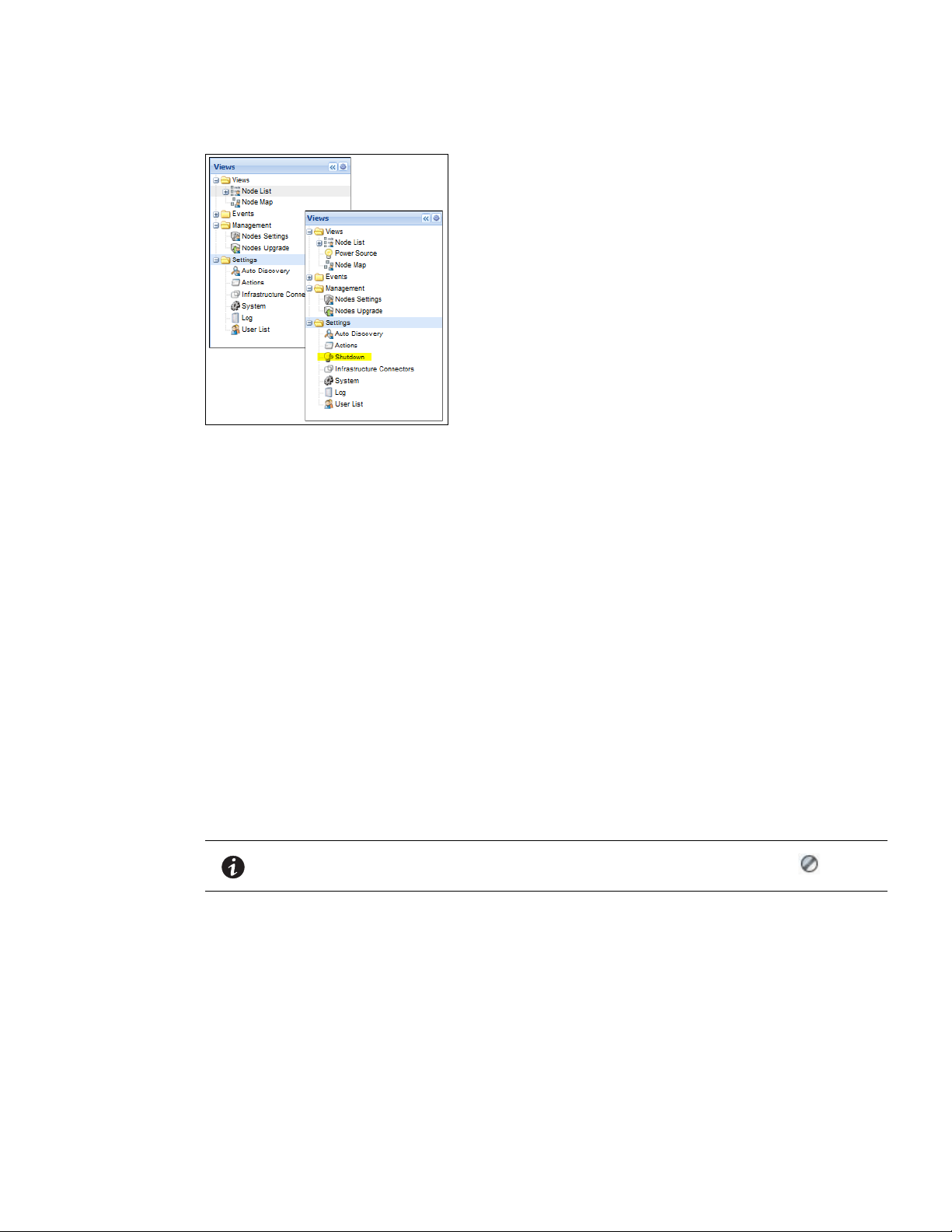
Figure 6. Shutdown Displays in the Settings Menu Hierarchy
3. From the Settings > Shutdown page, assign the following:
l
IP address of the UPS that powers the local computer (power source)
l
Shutdown configuration parameters (timer, duration, type of shutdown, and (if needed) shutdown script
l
Select or deselect (check or uncheck) the checkbox for standard shutdown sequence
Installation
License Code
The Eaton IPM monitors up to 10 devices (including UPS Web Card, ePDU, or Eaton IPP Shutdown Controller)
without a license key.
If there are more devices to be monitored, an appropriate licen
se is needed. The license can also be upgraded
later without reinstallation.
Only for “Silver” or “Gold” paid versions:
1. I n Set
tings > System > Edit System Information, enter the license product key that is printed on the
commercial CD booklet (inside the CD case):
l
ref 66925 Eaton IPM Silver License (11 to 100 device nodes)
l
ref 66926 Eaton IPM Gold License (101 to unlimited devices nodes)
NOTE Nodes that are not managed due to license limitation appear with this icon:
Operation
1. Use the Views > Node List menu item to supervise the current state of the compatible power devices
and applications.
2. Select a line in the list and the panels are updated with selected device information (see Figure 7).
Eaton Intelligent Power Manager (IPM) User’s Guide v1.40 P-164000289—Rev 2 13
Page 23

Installation
!
IMPORTANT
Figure 7. Node List Main Page
l
[Optional] If you have enabled the Shutdown module, the Views > Power Source menu item allows you to
supervise the current state of the UPS that powers the server running Eaton IPM. This menu is available
when you have enabled the Shutdown module in System > Settings > Edit Modules Settings.
l
The Events > Event List view allows you to view the device events.
l
The Management menu provides functions that allow you to mass configure and mass upgrade cards.
Installation Result
If you install a new
and your product settings.
l
At the end of the installation, the following shortcuts are created in the group Start > Programs > Eaton >
Intelligent Power Manager:
en Eaton Intelligent Power Manager: Starts the main Eaton IPM graphical interface
- Op
t Eaton Intelligent Power Manager: Starts the service
- Star
op Eaton Intelligent Power Manager: Stops the service
- St
ninstall Eaton Intelligent Power Manager: Uninstalls the program
- U
l
A service called “Eaton Intelligent Power Manager” is also created for the Database Acquisition Engine.
- This program continuously polls the status of Eaton
- This service automatically starts on machine boot-up.
- This service provides the Web Interface.
Eaton IPM
release without uninstalling the old one, you will keep your database
devices and Applications connected on the network.
l
A system tray icon displays the alarms on the local computer. Right-click this icon to display the same
shortcuts as in the Windows Start menu.
14 Eaton Intelligent Power Manager (IPM) User’s Guide v1.40 P-164000289—Rev 2
Page 24

Uninstalling the Eaton IPM
The following methods for uninstalling the
l
Access the control panel selection for your operating system to uninstall programs and remove the Eaton
Intelligent Power Manager
l
You can also uninstall from the shortcuts to remove the product and custom files (if you confirm the action):
Vx.xx package per your system instructions.
Start > Programs > Eaton > Intelligent Power Manager> Uninstall Intelligent Power Manager
Upgrading the Eaton IPM Product
If you install a new Eaton IPM Release without uninstalling the old release, you will keep your database and
your product settings. See “Nodes Upgrade” on page 74 for upgrade information. Also see “System Settings”
on page 29 for information on configuring automatic upgrade.
Installing/Uninstalling the Eaton IPM (Command Line)
You can install or uninstall the Eaton IPM product from a command line in order to deploy the software in a
group, with or without using the graphical interface. You can also configure protection settings from the
command line.
Detail of available command options can be obtained using the following command:
Eaton IPM
Installation
are available:
JRE Installation
<packageName> -help
<packageName> [COMMAND] [OPTION]...
The available commands are:
l
-install Launches the installation/upgrade process (default).
l
-uninstall Launches the process to uninstall the application.
The available options are:
l
-debug Displays debugging information on the console.
l
-silent Install the application silently.
Access the installation folder:
-dir <installPath>
Example
The command <packageName> -install -silent -dir "C:\Program Files\MyFolder" will install
Eaton IPM silently in C:\Program Files\MyFolder.
the
After the installation is completed, open a Web browser with the following URL:
http://<host>:4679/, where <host> is the host name or IP address of the machine hosting the Eaton IPM.
The installation of the Java Runtime Environment is Operating System platform dependent. All new Eaton
components have been developed tested for the Java version 1.6 or later. After installing the correct JRE, the
Eaton IPM must be reloaded to take account this new environment (see “JRE Prerequisites” on page 10 ).
Eaton Intelligent Power Manager (IPM) User’s Guide v1.40 P-164000289—Rev 2 15
Page 25

Installation
16 Eaton Intelligent Power Manager (IPM) User’s Guide v1.40 P-164000289—Rev 2
Page 26
Chapter 3 Configuration
This chapter describes how to configure the Eaton Intelligent Power Manager (IPM).
Configure Nodes
Each node (Network Management Card, proxy, or application) must have a valid IP address (or a DNS name) in
the range that you have entered for auto-discovery (s
Eaton IPM automatically receives the alarms (through notification or polling) without specific configuration on
the network card, proxies, or applications.
ee “Compatibility” on page 2).
For SNMP communication, configure the
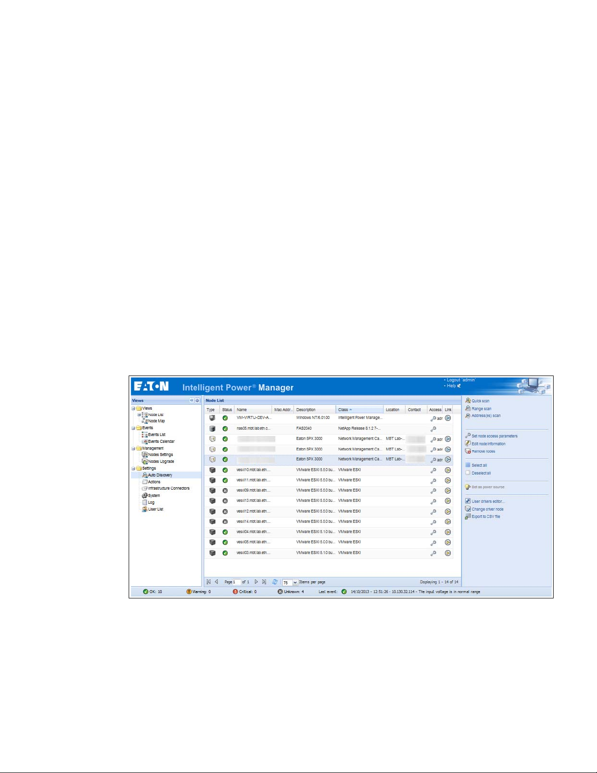
Discover Nodes Connected on the Network
To discover nodes connected on the network:
1. From the left-side Views panel
Discovery menu item.
2. From the right panel, select a discovery method (see Figure 8):
l
Quick Scan: Automatically performed when application starts
l
Range Scan: Click the Range Scan button
l
Address Scan: Click the Address Scan button
SNMP parameters using the System > Scan Settings selection.
of the Eaton IPM main interface window, select the Settings > Auto
Figure 8. Node List Page
Eaton Intelligent Power Manager (IPM) User’s Guide v1.40 P-164000289—Rev 2 17
Page 27
Configuration
Quick Scan
The Quick Scan request is a broadcast frame on 4679 IANA reserved port and 69 standard TFTP port. Using
the Quick Scan operation, you will discover any of the following within a few seconds:
- Network Management Cards Network-MS (example, 66102 / 103006826) and Modbus-MS (example,
03)
661
- PXGX2000, PXGX-UPS, ConnectUPS BD, ConnectUPS X, or ConnectUPS MS
- ePDUs
- Eaton Intelligent Power Protector (IPP) or Network Shutdown Module V3
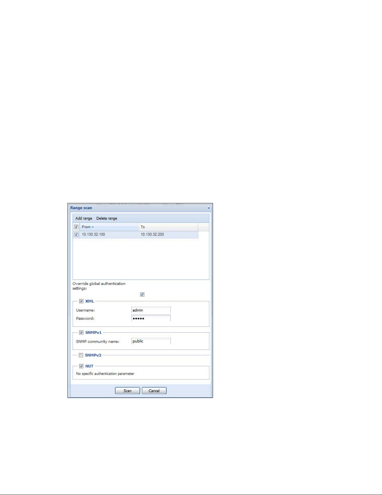
Range Scan
Using the Range Scan operation, you will discover the nodes that are outside of the Network segment and
nodes that are not compatible with the Quick scan feature. See “Compatibility” on page 2 to determine if your
node supports Quick scan feature.
In the Range scan dialog bo
authentication settings checkbox to specify authentication parameters that are different from global scan
settings (see Figure 9).
x, you can edit IP address ranges. You can also check (select) the Override global
Figure 9. Range Scan Dialog Box
18 Eaton Intelligent Power Manager (IPM) User’s Guide v1.40 P-164000289—Rev 2
Page 28
Configuration
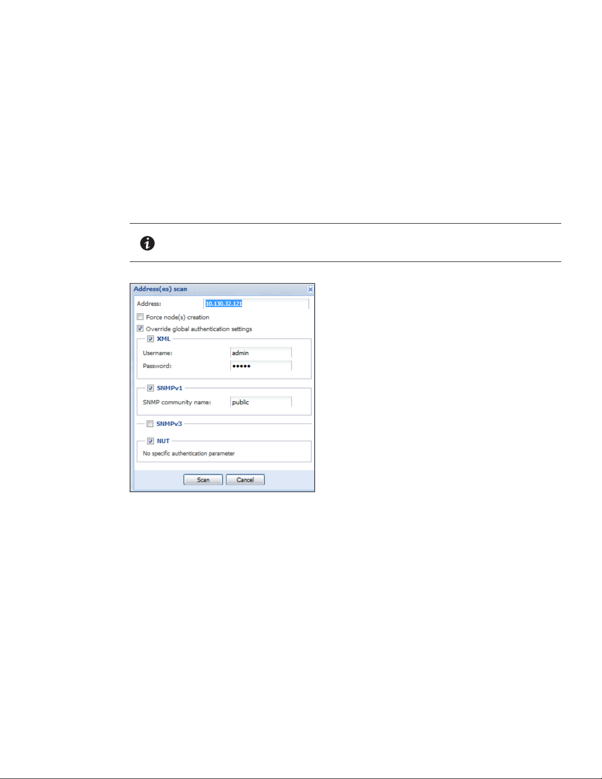
Address Scan
This type of node discovery performs a single address scan (or for several IP addresses separated by the “;”
character).
In the Address(es) Scan dialog bo
l
You can check (select) the Force node(s) creation checkbox to create a node with an IP address even if the
x, edit IP addresses to scan.
scan operation did not identify the device.
l
You can also check (select) the Override global authentication settings checkbox to specify authentication
parameters that are different from global scan settings (see Figure 10).
NOTE The option "Force node(s) creation" will create empty nodes if the scan operation did
not identify the devices. Then it is possible to assign a different driver to the nodes
created (see ).
Figure 10. Address(es) Scan Dialog Box (Example 1)
Eaton Intelligent Power Manager (IPM) User’s Guide v1.40 P-164000289—Rev 2 19
Page 29
Configuration
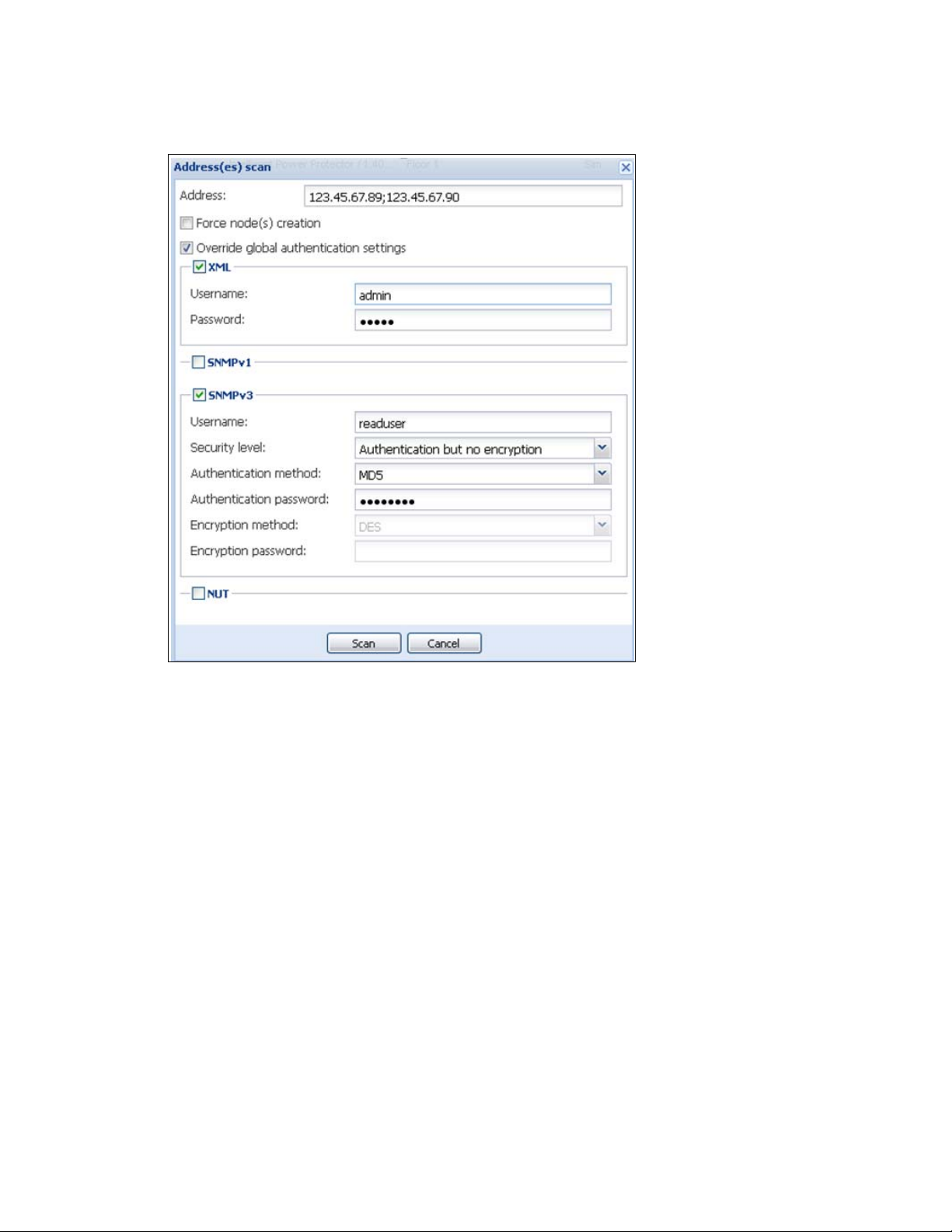
Figure 11. Address(es) Scan Dialog Box (Example 2)
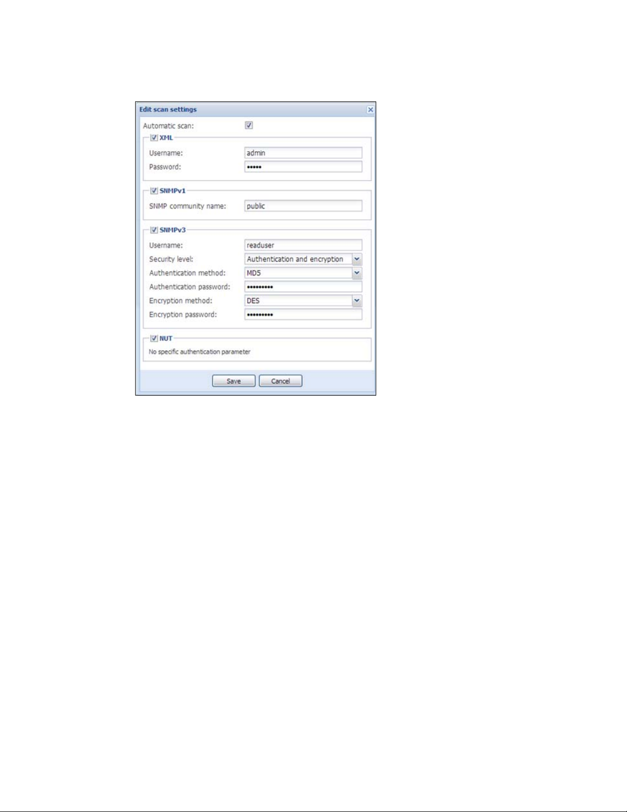
Scan Settings for Discovery
Administrators can set scanner authentication parameters that will be used as the default when discovering
new devices. These authentication settings can be set for the XML, SNMPv1, SNMPv3 and NUT protocols.
When discovered, manually or automatically, newly
parameters. Depending on the device-supported protocols, IPM will choose the needed parameters. See
“Compatibility” on page 2 to determine which protocols are supported.
The administrator can also activate the automatic scanner
a direct scan action of the administrator. For example, with automatic scan enabled, the presence of a new card
on the network would be auto-discovered and added.
To change scan settings:
1. From the left-side Views panel
menu item. The System page displays.
2. Click the Edit scan settings button on the right-side page. T
Figure 8).
3. Set the scan settings by selecting or deselect
drop-down list.
of the Eaton IPM main interface window, select the Settings > System
discovered devices will use these authentication
to add any automatically discovered devices without
he Edit scan settings dialog box displays (see
ing checkboxes, typing data, or make selections from the
20 Eaton Intelligent Power Manager (IPM) User’s Guide v1.40 P-164000289—Rev 2
Page 30
Configuration
Figure 12. Edit Scan Settings Dialog Box
Change driver node
After discovering a node, it is possible to assign a different driver to this node.
To change driver mode:
1. Select the Set
2. From the right-side panel, select Change driver node (see ).
3. By default, the driver of the node is sel
Then the node will use this new driver.
tings > Auto Discovery menu item.
ected. Choose another driver and click OK.
Eaton Intelligent Power Manager (IPM) User’s Guide v1.40 P-164000289—Rev 2 21
Page 31

Configuration
Figure 13. Change Driver Mode Dialog Box
Configure Node Settings
To configure node information and access parameters (administrators only):
1. From the left-side Views panel of the Eaton IPM main interface window, select the Settings > Auto
Discovery menu item.The Nodes List page displays.
2. Select a node from the Nodes List page.
3. Click the Edit node information button or click the Set node access parameters button in the right
panel.
4. The Edit Node Information dialog or the Access parameters dialog displays (see Figure 14 and Figure 15):
l
Edit node information dialog. The Edit node information dialog box allows editing the node name, the
user type, the node description and the associated load alarm threshold.
l
Access parameters dialog. You can define the access settings for all selected devices. Only relevant
settings are set, depending on the capabilities of the selected device capabilities.
22 Eaton Intelligent Power Manager (IPM) User’s Guide v1.40 P-164000289—Rev 2
Page 32

Figure 14. Node Access Parameters Dialog
Configuration
Figure 15. Edit Node InformationDialog
Configure Actions
From the Settings > Actions menu item, the following types of notifications or executable actions can be set
to occur as the result of specific Eaton IPM actions (see Figure 16):
l
l
l
E-mail
Execute script/program
Notification to the local alarm notification box, available from the System Tray icon
Eaton Intelligent Power Manager (IPM) User’s Guide v1.40 P-164000289—Rev 2 23
Page 33

Configuration
Figure 16. Actions Page
Figure 17. Create New Action Dialog
NOTE The “*” fields are required.
24 Eaton Intelligent Power Manager (IPM) User’s Guide v1.40 P-164000289—Rev 2
Page 34

Configuration
E-mail Notification Actions
You can set e-mail notifications for specific events in the Edit Action dialog box (see Figure 17). First, set the
event filter to specify the event trigger. Then, set the e-mail notification criteria.
Events Filter
You can filter the action according to the following:
l
Event criticalities: Critical, Warning, Normal, and Communication Lost
NOTE With this parameter, you can filter the notification according to the event level (see
“Node Events List” on page 61). If you select “Critical” as the filter, you will not
receive the associated “Normal” event informing that the device status changes
from “Critical” to “Normal.”
l
Event category: All Events, Alarms, Shutdown events, Power events, and Measures
NOTE The pen icon allows you to select and edit the event category.
l
View: The view that triggers the event
e-mail Criteria
To receive e-mail on UPS events:
l
You must indicate the SMTP server address and recipient e-mail address. Both logins and passwords are
used when the SMTP server requests authentication.
For advanced use:
l
Optional: You can customize the subject, such as when you use a third-party service provider to translate
e-mail into SMS.
l
Optional: You can specify that you want to receive a consolidation of the alarms that occurred during a delay
time duration. For example, if you specify none, each alarm generates an e-mail. With this setting, you will
receive more e-mail for the same number of events
Execute Script/Program Actions
In order to execute a program on UPS events, the program path is required.
NOTE The program is executed under the SYSTEM account.
l
If an action (script or program) cannot be executed under the SYSTEM account, it is necessary to modify the
execution context before it can be run.
l
To allow a user to run specific tools and programs with permissions that are different from those assigned to
the user's account, use the Windows “RunAs” command. This allows you to save the password (Windows
XP Service Pac 2 and more recent versions).
l
Use the following Microsoft command:
>
runas /profile /user:<windows_ login> /savecred <my_program.exe>
l
When first executed, a password is required; it is saved for subsequent executions.
Eaton Intelligent Power Manager (IPM) User’s Guide v1.40 P-164000289—Rev 2 25
Page 35

Configuration
Alarm Box Notification Actions
The alarms are displayed on the local computer in an alarm box (see Figure 18). The status part of the alarm
box is optional. It only appears if a power source has been declared in the Shutdown configuration settings.
Figure 18. Alarm Notification Box with System Tray Icon
The Alarm notification box is accessible from the System Tray icon (see Table 6 and Table 7). Click the icon to
open the window that displays the alarms on the local computer.
System Tray Icons
If no Power Source has been declared, the System Tray Icon can have the states described in Table 6.
Table 6. System Tray State Icons (Power So
Icon State Description
(BLUE) The System Tray Icon correctly receives alarms from Eaton IPM.
(GRAY) Communication is lost between the System Tray and the Eaton IPM.
If a Power Source has been declared, the System Tray Icon can have the states described in Table 7.
Table 7. System Tray State Icons (Power So
Icon State Description
The System Tray Icon correctly receives alarms from the Eaton IPM. AC is present on the
power source.
The System Tray Icon correctly receives alarms from the Eaton IPM. The power source
runs in battery mode.
urce not Declared)
urce Declared)
The System Tray Icon correctly receives alarms from the Eaton IPM. A Warning event
occurred on the power source.
The System Tray Icon correctly receives alarms from the Eaton IPM. A critical event
occurred on the power source.
Communication with the power source has failed.
26 Eaton Intelligent Power Manager (IPM) User’s Guide v1.40 P-164000289—Rev 2
Page 36

Configuration
NOTE Right-click the System Tray icon for fast access to the start and stop operations.
Advanced Events and Actions Customization
In the IPM installation folder, you can see a configs/scripts folder containing a sample user-defined action script
(sample_user_script.js).
You can modify this script or create new scripts that d
in this folder provides details about the expected structure and syntax for defining new actions and triggers.
efine very specific events and actions. The sample script
Advanced Sound Alarm Customization
To configure sound alarms on events:
1. In the file {INSTALL DIRECTORY}\Eaton\IntgelligentPowerManager\configs\config.js,
change the configuration as follows:
'systray':
{
'soundAlarm': false,
'notificationIcon': true,
'notificationBox': true
}
2. Change 'soundAlarm': false, to 'soundAlarm': true, as shown below:
'systray':
{
'soundAlarm': true,
'notificationIcon': true,
'notificationBox': true
}
3. Close and restart the Windows session so that this configuration is taken into account.
Configure User Accounts
To configure multiple user accounts:
1. From the left-side Views panel of the Eaton IPM main interface window, select the Settings > User List
menu item. The User List page displays (see Figure 19).
2. Click Ad
3. Type the user’s login and the user’s password (see Figure 20).
NOTE You can change the alarm sound by setting the Windows sound preferences from
Control Panel.
NOTE The Eaton IPM alarms are linked to the “Low Battery Alarm” sound that you can
change by selecting another .wav file.
d user. The Add user dialog box displays.
Eaton Intelligent Power Manager (IPM) User’s Guide v1.40 P-164000289—Rev 2 27
Page 37

Configuration
WARNING
4. Select the user's profile level. The following levels are available:
min: User will be able to access all the features
- Ad
r: User will only access the visualization and cannot set changes to the system or nodes
- Use
5. Click Cr
eate new user.
Figure 19. User List Page for User Account
Figure 20. Add User Dialog Box
Note that the Eaton IPM contains a default Administrator profile with:
l
“admin” as login
l
“admin” as password
For security reasons, Eaton recommends that you change the default password immediately after
the installation. A pop-up message provides a security warning if the password contains less than
eight characters.
28 Eaton Intelligent Power Manager (IPM) User’s Guide v1.40 P-164000289—Rev 2
Page 38

Configuration
System Settings
You can edit system settings. From the Settings > System menu item, you can edit system information and
settings (see Figure 21).
Figure 21. System Settings Page
Select one of the items on the System page, and then double-click the item, or single-click on the
corresponding button in the right-hand side menu:
l
Edit system information modifies contact and location information.
l
Edit language allows you to change the interface language (Czech, English, French, German, Japanese,
Korean, Polish, Portuguese, Russian, Simplified Chinese, Spanish, or Traditional Chinese).
l
Edit scan settings are the default access settings that are automatically set for new discovered nodes.
l
Edit update settings and Check for updates provide features that allow the system to automatically check
for Eaton software updates for you. When a new software version is detected on www.eaton.com, a wizard
displays and provides upgrade instructions for you. (Database information is retained with this operation.)
l
Edit modules settings allows you to enable/disable Eaton IPM optional modules:
nagement enables nodes settings mass configuration and nodes upgrade features
- Ma
utdown enables shutdown of the computer running Eaton IPM in the event of a power failure
- Sh
astructure Connections enables management of virtualized IT systems
- Infr
- Redu
- Use
ndancy provides support for >1 UPS in N+1 redundant configurations
r Drivers integrates new devices in the IPM supervision application by using predefined common
base objects and user-specific objects
NOTE This feature allows IPM to supervise any SNMP- or Network UPS Tools
(NUT)-available devices. You can customize and adapt the IPM acquisition engine to
any kind of Data Center device, such as HVAC, Rack controller, storage, or DC Power
System controller.
Eaton Intelligent Power Manager (IPM) User’s Guide v1.40 P-164000289—Rev 2 29
Page 39

Configuration
Automatic Data Purge
All IPM data (logs, measures and events) are stored in a database. This database automatically purges the
accumulated data when necessary according the purge parameter settings for the following parameters:
l
<maxTime>: Maximum timestamp for the oldest records (in ms)
l
<maxCount>: Maximum number of records, where the oldest records are removed first
These parameters can be modified in the “config.js” file in the logManager/purge section.
The default settings for purge include:
l
Data of type alarm (see events section) maxTime: 28 days maxCount: 50000
l
Data of type measure (see measures section) maxTime: 7 days maxCount: 200000
l
Data of type statistic (see stats section) maxTime: 28 days maxCount: 20000
l
Log system (see system section) maxTime: 28 days maxCount: 50000
Manage the Cisco UCS Manager Component
Enabling the Component
To enable the Infrastructure Connectors:
1. From the left-side Views panel of the Eaton IPM main interface window, select the Settings > System
menu item. The System page displays.
2. Click Ed
it modules settings in the right panel. The Edit modules settings dialog box displays (see
Figure 22).
3. Ensure that the Infrastructure Connectors checkbox is selected (checked).
4. Click Save.
Figure 22. Edit Modules Settings - Infrastructure Connectors
Add the Component
To add a Cisco UCS Manager:
1. From the left-side Views panel
of the Eaton IPM main interface window, select the Settings >
Infrastructure Connectors menu item. The Infrastructure Connectors page displays (see Figure 23).
2. Click A
30 Eaton Intelligent Power Manager (IPM) User’s Guide v1.40 P-164000289—Rev 2
dd a connector in the right panel. The Add a connector dialog box displays (see Figure 24).
Page 40

Figure 23. Select Add a Connector
Configuration
Figure 24. Add a Connector Dialog for Cisco UCS Manager
3. From the Add a Connector dialog, select Cisco UCS Manager from the Product drop-down list (see
Figure 24).
4. Add identification information for the selected connector:
l
Product: Cisco UCS Manageris already selected in the drop-down list.
l
Hostname or IP address: Type Cisco UCS Manager IP address
l
Port: Port number
l
Username: Type Cisco UCS Manager Administrator Username for the Administrator with admin rights
on the Cisco UCS Manager
l
Password: Type Cisco UCS Manager Administrator Password
5. Click Sa
ve after the fields are updated.
6. When the component is connected, the Cisco UCS Manager displays on the Infrastructure Connectors
(see Figure 25).
page
7. If the component does not display, refresh the page. Also, check the log to ensure the Event details
lay with an OK connection state (see Figure 26).
disp
Eaton Intelligent Power Manager (IPM) User’s Guide v1.40 P-164000289—Rev 2 31
Page 41

Configuration
Figure 25. Cisco UCS Manager Component Added
Figure 26. Event Details
Remove the Component
To remove a Component, right-click on the component in the list. From the action box, click Remove connector
(see Figure 27).
Figure 27. Remove a Connector
32 Eaton Intelligent Power Manager (IPM) User’s Guide v1.40 P-164000289—Rev 2
Page 42

Configuration
Edit a Component
To edit a Component, right-click on the component in the list. From the action box, click Edit connector (see )
the Edit connector dialog displays.
NOTE IPM currently doesn't allow you to edit the IP address.To edit a new IP address,
please remove the connector and add another connector.
.
Figure 28. Edit a Connector
.
Figure 29. Edit Connector Dialog
Eaton Intelligent Power Manager (IPM) User’s Guide v1.40 P-164000289—Rev 2 33
Page 43

Configuration
Configure the Cisco UCS Manager Component
To set the UCS Manager component configuration:
1. Select Nodes Settings > “the UCS Manager component” > Shutdown Setting and click the pen icon
(see Figure 30).
.
Figure 30. Shutdown Settings Configuration
Power source, Load Segment, Remote shutdown, Shutdown duration, Shutdown after value are standard IPM
options and are not described here. The following topics are discussed:
l
difference between “current” and “future” options
l
power capping timer
l
global power allocation policy
l
policy-driven power capping
l
manual blade-level power capping
l
power control policy and priority
l
power budget
Difference Between “Present” and “Future” Options
The current Power Budget or Policy Priority are the values that are currently set in your UCS Manager, any
change on those in IPM will set permanently the new values on UCS manager
The future Power Budget or Policy Priority are the values that will be set temporary in your blade when the
wer failure occurs, once the power come back the older values will be set back.
po
Power Capping Timer
The power capping timer will set the Power Capping after the duration set (in seconds). It launches immediately
after a power failure. The value -1 signifies no timer set.
34 Eaton Intelligent Power Manager (IPM) User’s Guide v1.40 P-164000289—Rev 2
Page 44

Configuration
Figure 31. Shutdown Settings-Set Power Capping Change Timer
Global Power Allocation Policy
The global cap policy is a global policy that specifies whether policy-driven chassis group power capping or
manual blade-level power capping will be applied to all servers in a chassis.
Two global allocation policies in IPM are:
l
policy-driven power chassis group power capping
l
manual blade-level power capping
Policy-driven Chassis-level Power Capping
When policy-driven power chassis group power capping is selected in the global cap policy, Cisco UCS can, at
the blade level, compute the amount of power allocated to a chassis based on priority.
A service profile has to be attached to a blade to set priorities on a blade
Figure 32. Policy-driven Power Chassis Group Power Capping
Eaton Intelligent Power Manager (IPM) User’s Guide v1.40 P-164000289—Rev 2 35
Page 45

Configuration
Manual Blade-level Power Capping
When manual blade-level power capping is configured in the global cap policy, you can manually set a power
cap for each blade server in a Cisco UCS instance.
If the server encounters a spike in power usage that m
Cisco UCS Manager does not disconnect or shut down the server. Instead, Cisco UCS Manager reduces the
power that is made available to the server. This reduction can slow down the server, including a reduction in
CPU speed.
Figure 33. Manual Blade Power Capping
eets or exceeds the maximum configured for the server,
Power Control Policy and Priority
Cisco UCS uses the priority set in the power control policy, along with the blade type and configuration, to
calculate the initial power allocation for each blade within a chassis. During normal operation, the active blades
within a chassis can borrow power from idle blades within the same chassis. If all blades are active and reach
the power cap, service profiles with higher priority power control policies take precedence over service profiles
with lower priority power control policies.
Priority is ranked on a scale of 1-10, where 1 indicates the highest priority and 10 indicates lowest priority. The
efault priority is 5.
d
For mission-critical applications, a special power priority cal
no-cap prevents a Cisco UCS from leveraging unused power from that particular blade server. The server is
allocated the maximum amount of power that the blade can reach.
36 Eaton Intelligent Power Manager (IPM) User’s Guide v1.40 P-164000289—Rev 2
led no-cap is also available. Setting the priority to
Page 46

Figure 34. Shutdown Settings-Current Power Default Setting (Priority 5)
Configuration
Figure 35. Shutdown Settings-Current Power Not Set Due to No Service Profile
Power Budget
Power budget allows you to specify the maximum amount of power (in watt) that the server can consume at
one time.
If the value is set to “unbounded,” no po
temporary power budget is disabled. The server can use as much power as it requires.
Figure 36. Shutdown Settings-Future Temporary Power Budget is Disabled
wer usage limitations are imposed upon the server and the future
Eaton Intelligent Power Manager (IPM) User’s Guide v1.40 P-164000289—Rev 2 37
Page 47

Configuration
Common Errors and Notifications for the Cisco UCS Manager Component
1. You can't set a shutdown to a blade that doesn't have a service profile assigned.
Figure 37. No Service Profile
2. You can't set a priority to a blade that doesn't have a service profile assigned.
Figure 38. No Service Profile
3. IPM can't find a UCSM on the IP provided.
Figure 39. UCS Manager Not Found
38 Eaton Intelligent Power Manager (IPM) User’s Guide v1.40 P-164000289—Rev 2
Page 48

4. A wrong value has been set for the power budget.
Figure 40. Wrong Power Budget Set
5. A new power budget has been requested by the client
.
Configuration
Figure 41. New Power Budget Requested
6. A new power budget has been successfully set by the server.
Figure 42. New Power Budget Successful
Eaton Intelligent Power Manager (IPM) User’s Guide v1.40 P-164000289—Rev 2 39
Page 49

Configuration
40 Eaton Intelligent Power Manager (IPM) User’s Guide v1.40 P-164000289—Rev 2
Page 50

Chapter 4 Supervision
This chapter describes supervision features in the Eaton Intelligent Power Manager (IPM).
Access to the Monitoring Interface
You can access the interface locally or remotely.
Local Access
From the system where Eaton IPM is installed, you can use the following shortcut:
Start > Programs File > Eaton > Intelligent Power Protector > Open Eaton Intelligent Power Protector
Remote Access
1. From a remote computer, you can type either of the following URLs in a Web browser:
https://<name or IP address of computer hosting Eaton IPM>:4680/
-or-
http://<name or IP address of computer hosting Eaton IPM >:4679/
2. In SSL mode, accept the certificate using the procedure provided by your Browser.
3. Enter the login and password.
Node List View
The Node List view results from the Settings > Auto Discovery menu item selection. The following default
columns are displayed in this page (see Figure 43):
l
Ty p e : Graphical icon to differentiate UPS/ePDU and applications
l
Status: Status icon represents the severity of the most critical event active on the monitored device
l
Name: IP address, the DNS name or user-defined name
l
Description: Product name or description
l
Location: Node location
l
Contact: Node contact
l
Link: Link to the device Web site (if available)
Eaton Intelligent Power Manager (IPM) User’s Guide v1.40 P-164000289—Rev 2 41
Page 51

Supervision
Figure 43. Node List View
You can sort (ascending or descending) your
Location / Load Level and so forth). You can also add columns, as illustrated in Figure 44.
device list by clicking the column titles (Status / Name / Description/
Figure 44. Adding Columns in Node List View
42 Eaton Intelligent Power Manager (IPM) User’s Guide v1.40 P-164000289—Rev 2
Page 52

Flexible Panels View
To select which panels display in the view:
1. Select a device/applications in the list and Select panels displays in the right side of the window.
2. Click the bar title to collapse/extend the panel.
3. You can also show or hide all the views menu or selection view menu.
Supervision
4. Click the selection button
Figure 45).
to select which panels you want to add in the selection view (see
Figure 45. Panel Selection Dialog Box
NOTE Some of the panels are only available for specific node types.
Information Panel
The following node information displays in this panel (see Figure 46):
l
166.99.xx.yy: DNS name (or IP address) displayed near the “status icon”
l
Description: Commercial product name
l
Nominal Apparent Power: Device load capacity in VA
l
IP address: Device IP address
l
Mac address: Device MAC address
l
Serial Number: Device serial number (if available)
l
Class:. Type of card
Eaton Intelligent Power Manager (IPM) User’s Guide v1.40 P-164000289—Rev 2 43
Page 53

Supervision
l
Location: Device location (value of syslocation object can also be configured in the Device page)
l
Contact: Device contact (value of syscontact object can also be configured in the Device page)
l
Link: Link to device Web site (if available)
NOTE The information displayed in this panel depends on the node types you are viewing.
Figure 46. Information Panel
Status Panel
The following node status displays in this panel (see Figure 47):
l
Power source: AC Power / Batter y
l
Battery state: Charging / Discharging / Default / Floating / Resting
l
Load Level: Output load level of the device
l
Battery capacity: Battery capacity of the device
l
Battery run time: Device remaining backup time
l
Master Output: Main output status (ON/OFF/Internal Failure/On Automatic Bypass/Manual ByPass/
Overload)
l
Output Outlet status: Output outlet status (ON/OFF) for outlet or load segment
NOTE The information displayed in this panel depends on the node capabilities.
44 Eaton Intelligent Power Manager (IPM) User’s Guide v1.40 P-164000289—Rev 2
Page 54

Supervision
Figure 47. Status Panel
Outlets Panel
The following outlets status information displays for the selected ePDU in this panel (see Figure 48):
l
Contextual information is provided when the mouse is over the outlet.
l
When you select an outlet in this panel, the Graph panel displays the information for this outlet.
l
You must also select Outlet information in the Graph settings dialog (accessible through the graph settings
button in the Graph panel)
Figure 48. Outlet Panel
Eaton Intelligent Power Manager (IPM) User’s Guide v1.40 P-164000289—Rev 2 45
Page 55

Supervision
The outlet state is color-coded in the display (see Table 8).
Table 8. Outlet Color Codes
Icon Color Description
Green Powered (ON)
Red Not powered (OFF)
Gray Outlet status unknown
Measures Panel
This panel displays the selected device electrical parameters for single-phase or three-phase devices,
depending on the node capabilities (see Figure 49 and Figure 50).
Figure 49. Measures Panel (Single-Phase)
46 Eaton Intelligent Power Manager (IPM) User’s Guide v1.40 P-164000289—Rev 2
Page 56

Figure 50. Measures Panel (Three-Phase)
Environment Panel
This panel displays the selected device sensor information if a device is attached (see Figure 51):
Supervision
l
Temperature: Temperature (in °C or °F)
l
Humidity: Humidity level
l
Input #1: Status of first contact (open / closed)
l
Input #2: Status of second contact (open / closed)
NOTE For more information about the two optional input connections, please refer to the
Eaton Environmental Monitoring Probe (EMP) User Guide.
Figure 51. Environment Panel
Graph Panel
This panel displays the graph of the main measures of the selected device (see Figure 52):
l
The button allows you to zoom in the graph.
l
The button allows you to select the data you want to display in the graph.
Eaton Intelligent Power Manager (IPM) User’s Guide v1.40 P-164000289—Rev 2 47
Page 57

Supervision
Figure 52. Graph Panel
Synoptic Panel
This panel displays the selected device synoptic (see Figure 53). A tool tip displays when you move the mouse
over one of the functional block.
Figure 53. Synoptic Panel
The Synoptic color coded icons display for the following (see Table 9):
l
UPS modules
l
Battery modules
l
Electrical flows
l
Electrical power sources at UPS input
l
Load at UPS output, with status linked to UPS output status
l
Combined flow status and load status
48 Eaton Intelligent Power Manager (IPM) User’s Guide v1.40 P-164000289—Rev 2
Page 58

Table 9. Synoptic Panel Icons
WARNING
Symbol Color Description
UPS Modules
AC/DC DC/AC Bypass Green Status OK and Active
Supervision
AC/DC DC/AC Bypass
AC/DC DC/AC Bypass
Battery Modules
Electrical Flows
Red Internal Fault and Inactive
Gray Status OK and Inactive or Unknown
Green Status OK
Orange Battery charge is less than 50%
Red Battery fault or End-of-backup
Gray Battery status unknown
Yellow Current flow through the cable
NOTE The object a
current flow.
Gray No current flow through the cable
nimation gives the direction of the
Although there is no current flow through the cable, the cable may be under voltage.
Electrical Power Source at UPS Input
Green Source powered. Status OK
Gray Source not powered or status unknown
Eaton Intelligent Power Manager (IPM) User’s Guide v1.40 P-164000289—Rev 2 49
Page 59

Supervision
Table 9. Synoptic Panel Icons (Continued)
Symbol Color Description
Load at UPS Output
Green Load powered and protected. Status OK
Red Load not powered
Gray Load status not known
Combined Color Code: Flow and Power Source Status
Green/Yellow Electrical power source is powered and provides
electrical flow
Green/Gray Electrical power source is powered and does not provide
electrical flow
Combined Color Code: Flow and Load Status
Yellow/Green Load powered and protected
Gray/Red Load not powered
Power Source
The Power Source panel displays information on the device that powers the selected application running on
the server (see Figure 54).
Figure 54. Power Source7
50 Eaton Intelligent Power Manager (IPM) User’s Guide v1.40 P-164000289—Rev 2
Page 60

Supervision
Powered Applications
The Powered applications panel displays information for the software applications (shutdown agents on the
servers) that are powered by the selected device (see Figure 55)”
l
Status
l
Name
l
Shutdown diagram
l
Shutdown duration
l
Outlet group
Figure 55. Powered Applications
Events Panel
This panel displays the events list of the selected node (see Figure 56). You can sort the events according to
status, date, and message by clicking the column header.
Figure 56. Events Panel
Statistics Panel
This panel displays the statistics of the selected node (see Figure 57). The button allows you to select the
time interval for the statistics. You can adjust the time interval by cli
“To” dates.
The statistics computed data is as follows:
l
Active Consumption in Kilowatt-hour
l
Average Active Power in Watts
l
Power Failure Count
l
Power Failure Cumulated Duration
l
Battery Fault Count
l
Internal Failure Count
cking the two buttons with the “From” and
Eaton Intelligent Power Manager (IPM) User’s Guide v1.40 P-164000289—Rev 2 51
Page 61

Supervision
l
Overload Count
l
Warning Alarm Count
l
Critical Alarm Count
l
Output Off Count
l
Communication Lost Count
NOTE This information depends on device capabilities.
Subviews
Figure 57. Statistics Panel
Power Components
Figure 58 illustrates the Power Components View. This panel displays the components of a redundant UPS
system if the Redundancy feature is activated (see Chapter 8, “Redundancy” on page 97).
Figure 58. Power Component View (Sub-view of Power Source View)
Defining Sub-views
When you need to monitor large configurations, it is helpful to define several sub-views and then filter the
nodes or events in these categories. You can select many criteria in order to organize your tree.
To define a sub-view:
1. Select a view in the
Figure 59).
2. Right-click this selection. The contextual sub-view menu displays (see Figure 60).
Views > Node List, such as Category: “Devices” or Location “HPO Finland” (see
3. Click Cr
52 Eaton Intelligent Power Manager (IPM) User’s Guide v1.40 P-164000289—Rev 2
eate a sub-view from … and follow the instructions.
Page 62

Figure 59. Views > Node List Example Hierarchy
Supervision
Figure 60. Contextual Sub-view Menu
To filter the nodes in this sub-view:
1. Select a view in the
2. Right-click this selection. The contextual menu sub-views displays (see Figure 60).
3. Click Edit a Filt
4. Click Ad
d rule, then type the Object, Operation and Values.
NOTE With the setup shown in
Views > Node List, such as “Location: Computer Room” (see Figure 59).
er View. The View Filter Rules dialog box displays (see Figure 61).
Figure 61, t
whose location field contains the value “Computer Room.”
Eaton Intelligent Power Manager (IPM) User’s Guide v1.40 P-164000289—Rev 2 53
his filtered view allows you to view the devices
Page 63

Supervision
Figure 61. View Filter Rules Dialog Box
As the result of creating a subview, The following default informatio
n appears in the Applications List View page
(see Figure 62).
l
Ty p e : Application
l
Status: Status criticality of the server
l
Name: Value configured in the Applications screen (by default this is an IP address or a DNS name)
l
Description: Operating system
l
Power source: UPS that powers the Eaton IPP application/computer
l
Estimated Run Time to shutdown: Operating time in the event of a utility supply loss
l
Shutdown duration: Duration needed by the system to carry out its shutdown procedure (in seconds)
l
Power Source shutoff: After the application is stopped, this information shows whether the power source
is stopped or not
l
Outlet group: UPS load segment
l
Link: Link to the Web supervision interface of the Eaton IPP or Network Shutdown Module V3 module
54 Eaton Intelligent Power Manager (IPM) User’s Guide v1.40 P-164000289—Rev 2
Page 64

Supervision
NOTE The Eaton IPP or Network Shutdown Module V3 running on other computers in the
network can be monitored in this view.
Figure 62. Applications List View Page
Sharing Sub-views
A customized sub-view is “attached” to the user that created it. It is private. The customized sub-view is
marked with a small man next to the icon of the sub-view (see Figure 63).
Figure 63. Shared View with Marker (left) and Public View without Marker (right)
If the owner of the sub-view wants to allow others to use the sub-view, he needs to share the view.
Eaton Intelligent Power Manager (IPM) User’s Guide v1.40 P-164000289—Rev 2 55
Page 65

Supervision
To share the view:
1. Right-click the view to open the contextual menu (see Figure 64).
Figure 64. Contextual Sub-view Menu
2. Click Share this View (see Figure 65).
Figure 65. Share the View Selection
NOTE Customizing a view cancels the sharing of this view. To allow all the users who were
sharing this file to view it, the owner of the view must share it again.
Device Supervision
The bar at the bottom of the page provides the status of nodes being supervised. Note the following in
Figure 66:
l
14 nodes are OK
l
4 nodes are in Warning status
l
2 nodes are in Critical status
l
0 nodes are in Unknown status
Figure 66. Bottom Bar for Device Supervision
56 Eaton Intelligent Power Manager (IPM) User’s Guide v1.40 P-164000289—Rev 2
Page 66

Map View
Supervision
This supervision map allows you to spatially represent your network nodes and uses “drag and drop”
functionality.
NOTE Clicking a node icon updates the information for that node on the right-hand panel.
Create a Customized Map View
The customized map view is accessed on the left-side menu using the Views > Node Map selection. The map
is automatically generated. (Icons are automatically placed on the Map and IP address assigned.)
The contextual tool button on the Node Map title bar provides tools to modify the map (see Figure 67):
l
Change theme offers three kinds of icons representations (small tower icons, large tower icons, and large
rack icons).
l
Manage backgrounds allows you to import a new background image in the supervision tool (png, jpeg, and
gif picture format types are supported). You can select a background already in the supervision tool for the
map or remove the background images.
l
Regroup nodes rearranges the icons position on the Map.
l
Add a label allows to create a user-defined text and to place it on the Map through drag and drop.
NOTE To delete a label, right-click the label and then click Delete.
Figure 67. Contextual Tools Menu
Map Examples
This section provides examples of the following maps:
l
World Map View
l
Country Map View
l
Server Room Map View
Eaton Intelligent Power Manager (IPM) User’s Guide v1.40 P-164000289—Rev 2 57
Page 67

Supervision
Figure 68. World Map View
Figure 69. Country Map View
58 Eaton Intelligent Power Manager (IPM) User’s Guide v1.40 P-164000289—Rev 2
Page 68

Supervision
Figure 70. Server Room Map View
Eaton Intelligent Power Manager (IPM) User’s Guide v1.40 P-164000289—Rev 2 59
Page 69

Supervision
Events
List Representation
Select Events > Events List to display the Events List page (see Figure 71). All new alarms are stored in this
log. You can sort the alarms according to the Status, Date, Name, and Acknowledge (ACK) fields.
Figure 71. Events List Page
The following functions are available:
l
Acknowledge selected events: Adds a check box in the Ack column for selected events
l
Acknowledge all events: Adds a check box in the Ack column for all event.
NOTE When an alarm is acknowledged, it is marked with a check box but it is still viewable
in this Event list. The acknowledged alarms disappear in the Power Source > Event
dedicated portal panel.
l
Export Logs: Creates a logs.csv file with the following syntax:
"Date","Node","Type","Level","Object","Value","Message",
NOTE The export command may take several seconds before allowing the download in
order to create the logs file.
l
Purge Logs: Delete all logs (specify a date)
l
Select all: Selects all displayed events
l
Deselect all: Deselects all selected events
60 Eaton Intelligent Power Manager (IPM) User’s Guide v1.40 P-164000289—Rev 2
Page 70

Supervision
Calendar Representation
Select Events > Events Calendar to display the Events Calendar page. In this matrix representation, each line
is a week and each column is a day in the week. If you select a day or an interval (with the date-picker or using
the shift+click command), the Events and Statistics panels provide all information for this selection and
automatically refresh when new statistics are computed (see Figure 72).
Figure 72. Event Calendar Page
Node Events List
The icons in the different views represent the event severity.
NORMAL With this event, the UPS device is returning to a normal status.
Normal Event list (UPSs, ePDUs, Applications, or Generic devices):
l
Communication with device is restored
l
Communication restored with UPS
l
The system is powered by the utility
l
The UPS output is on
l
Communication restored with UPS
l
Battery OK
l
UPS returns to normal load
l
UPS OK
l
Bypass: Return on UPS
l
End of low battery alarm
l
The outlet group 1 is on
l
The outlet group 2 is on
l
Communication failure with environment sensor
Eaton Intelligent Power Manager (IPM) User’s Guide v1.40 P-164000289—Rev 2 61
Page 71

Supervision
l
Communication restored with environment sensor
l
Humidity is in normal range
l
Temperature is in normal range
l
Input {x} on
l
Input {x} off
l
End of warning alarm
l
End of critical alarm
l
Redundancy restored
l
Protection restored
ePDU Normal Event List (Specific to ePDUs):
l
The input frequency is in normal range
l
The input temperature is in normal range
l
The input voltage is in normal range
l
The input {x} is in normal load
l
The section {x} current is in normal range
l
The section {x} voltage is in normal range
l
The outlet group {x} current is in normal range
l
The outlet group {x} is in normal load
l
The outlet group {x} is on
l
The phase {x} output load is in normal range
l
The output frequency is in normal range
l
The output load is in normal range
l
The output voltage is in normal range
WARNING A problem occurred on the UPS device. Your application is still protected.
Warning Event List (UPSs, ePDUs, Applications, Generic devices):
l
The system is powered by the UPS battery
l
Output on automatic bypass
l
Output on manual bypass
l
Humidity is below low threshold
l
Humidity is above high threshold
l
Temperature is below low threshold
l
Temperature is above high threshold
l
Warning Alarm (a generic Warning alarm is active on the device)
l
The device is under its load alarm threshold
l
The device is over its load alarm threshold
l
Protection lost
l
Redundancy lost
l
Shutdown in <time>
l
Remote Communication Error (remote communication or configuration issue is detected)
62 Eaton Intelligent Power Manager (IPM) User’s Guide v1.40 P-164000289—Rev 2
Page 72

Supervision
CRITICAL A serious problem occurred on the UPS device. This problem requires an urgent action. Your
application might NOT BE powered.
Critical Event List (UPSs, ePDUs, Applications, Generic devices):
l
The UPS output is off
l
The outlet group 1 is off
l
The outlet group 2 is off
l
Battery fault
l
UPS overload
l
UPS fault
l
Low battery alarm
l
Applications must stop immediately...
l
System shutdown in progress...
l
Critical alarm (a generic Critical alarm is active on the device)
ePDU Critical Event List (Specific to ePDUs):
l
The input frequency is out of range
l
The input temperature is above high threshold
l
The input temperature is below low threshold
l
The input voltage is above high threshold
l
The input voltage is below low threshold
l
The input {x} is overload
l
The section {x} current is too high
l
The section {x} current is too low
l
The section {x} voltage is too high
l
The section {x} voltage is too low
l
The outlet group {x} current is too high
l
The outlet group {x} current is too low
l
The outlet group {x} is overload
l
The outlet group {x} is off
l
The phase {x} output is overload
l
The output frequency is out of range
l
The output is overload
l
The output voltage is above high threshold
l
The output voltage is below low threshold
COMMUNICATION LOST Communication is lost.
Communication Lost Event List:
l
Communication failure with Device or Application
DEVICE IS NOT MANAGED Device is not managed
l
Your device is not managed due to license limitation. Use the Settings > System selection to enter a Silver
or Gold license code.
Eaton Intelligent Power Manager (IPM) User’s Guide v1.40 P-164000289—Rev 2 63
Page 73

Supervision
Launching the Device Web Interface
From the Status panel, you can access the Web page for Eaton cards, including an on-board Web server. Click
the associated Web link for http access (blue icon
Figure 73 provides examples of the opening view from different Web interfaces.
)
or the https access (yellow icon ).
Figure 73. Opening View in Different Interfaces
Node List Export to CSV File
To export data displayed in the Node list, click the button in the top right corner of the Node list and select Export
to CSV file (see Figure 74 ).
If some nodes are selected in the list, the exported file cont
selected, the exported file contains data for all the nodes in the list. Only data from currently displayed columns
are exported.
64 Eaton Intelligent Power Manager (IPM) User’s Guide v1.40 P-164000289—Rev 2
ains only data for the selected nodes. If no node is
Page 74

Supervision
Figure 74. Export to CSV File
The function is also available from the Auto Discovery > Export to CSV file menu selection.
Eaton Intelligent Power Manager (IPM) User’s Guide v1.40 P-164000289—Rev 2 65
Page 75

Supervision
66 Eaton Intelligent Power Manager (IPM) User’s Guide v1.40 P-164000289—Rev 2
Page 76

Chapter 5 Shutdown
The Eaton Intelligent Power Manager (IPM) provides local computer graceful shutdown when connected to a
UPS through either a Network Management Card, USB port or RS-232 port.
This shutdown feature can be enabled or disabled from the Se
path.
Shutdown Configuration
To access the shutdown configuration options and verify that the Shutdown Module is enabled (administrator
access):
1. From the left-side Vie
menu item.The Shutdown page displays (see Figure 75).
The following configuration options are provided on the righ
l
Edit power source
l
Edit shutdown configuration
l
Edit advanced shutdown criteria
l
Edit UPS configuration
l
Test access
l
Test shutdown
ttings > System > Modules Settings selection
NOTE Refer to the Eaton Intelligent Power Protector (IPP) User’s Guide for a detailed
description of the Shutdown feature.
NOTE When the Shutdown feature is enabled, the software displays a communication
error until the Power Source is correctly configured as described in “Shutdown
Configuration”.
ws panel of the Eaton IPM main interface window, select the Settings > Shutdown
t-side panel of the Shutdown page:
Figure 75. USB/Serial Power Source on Shutdown Page
To configure shutdown, perform the following actions:
1. Click the Ed
it Power Source button.
2. In the Power source field, select the UPS that powers the computer hosting the Eaton IPM.
Eaton Intelligent Power Manager (IPM) User’s Guide v1.40 P-164000289—Rev 2 67
Page 77

Shutdown
3. Select the UPS Load Segment that is powering the server.
4. Type the login and password if necessary (depends on the connectivity).
5. Click Sa
ve.
Shutdown Through Hibernate
If available with your operating system, there are a number of advantages to using the hibernation feature
(available from
information (including work in progress) is automatically saved to the disk. The computer is also de-energized.
When mains power returns, all the applications re-open exactly as they were before the computer shut down
and you return to the application work environment.
Microsoft® Windows® 2000 and later versions). When the computer is shutting down, all system
The Hibernate function must first have been activated in the op
Windows control panel Hibernate tab
Power Source View
When the Shutdown feature is configured, select the Views > Power Source menu item to perform the
following (see Figure 76):
l
To supervise the information from the UPS that powers the Eaton IPM computer.
l
To drag and drop the panels in this window to different locations to personalize your viewing preference.
erating system in the power options on the
NOTE If you select hibernate, but your computer does not have this function, the Eaton
IPM will still protect the system by carrying out the normal (default) shutdown
action.
Figure 76. Power Source View
68 Eaton Intelligent Power Manager (IPM) User’s Guide v1.40 P-164000289—Rev 2
Page 78

Shutdown Sequence
The Eaton IPM can acquire shutdown alarms from the Eaton IPP with the Shutdown Controller enabled.
Shutdown
NOTE Refer to the Eaton Intelligent Power Protector (IPP) User’s Guide for more
information about Shutdown sequence and Shutdown Use Case.
Eaton Intelligent Power Manager (IPM) User’s Guide v1.40 P-164000289—Rev 2 69
Page 79

Shutdown
70 Eaton Intelligent Power Manager (IPM) User’s Guide v1.40 P-164000289—Rev 2
Page 80

Chapter 6 Advanced Management
This chapter describes Eaton Intelligent Power Manager (IPM) advanced management features.
Nodes Settings
Single Node Configuration Display
The Eaton IPM can display the card and application configuration for other nodes on the network.
To display configurations for other nodes on the network (administrator access):
1. From the left-side Views panel
Nodes Settings menu item. The Node List page displays.
2. Select one node (card) from the Node List page (see Figure 77).
3. After a few seconds, on the right hand, the Node configuration panel is updated.
4. If you wish to save a standard node configuration (for
Configurations > Export Configuration file to export this configuration to a file.
of the Eaton IPM main interface window, select the Management>
example to deploy to other similar nodes), use the
Figure 77. Nodes Settings View
Single Card Settings
Eaton IPM can configure a remote Network Management Card.
To configure a remote Network Management Card (administrator access):
1. From the left-side Views panel
Nodes Settings.
2. Select one node (one card) from the Node List page (see Figure 77).
of the Eaton IPM main interface window, select the Management >
Eaton Intelligent Power Manager (IPM) User’s Guide v1.40 P-164000289—Rev 2 71
Page 81

Advanced Management
!
IMPORTANT
3. Click the Node List button , select Set Login Parameters, and enter the card Login and Password.
The access status changes from Access Denied (
After a few seconds, the Node configuration panel is updated.
) to Access OK ( ).
4. Click on the Edit button
5. In the Network Settings Configuration dialog box, chec
new values (see Figure 78).
Figure 78. Network Section
6. Click Apply to apply to the selected node (card).
NOTE The parameters that have different card and configurations values (unsynchronized)
are indicated by the
, or load a previously saved configuration.
sign.
k the parameters you want to change and type the
7. Select the parameters you want to synchronize (with the check box).
8. Click Synchronize.
Some advanced parameter details are not displayed in the
. For these details, you will need to change the advanced parameters details directly on one
box
device and then synchronize the configuration from this device to other devices (see Figure 79).
72 Eaton Intelligent Power Manager (IPM) User’s Guide v1.40 P-164000289—Rev 2
Network Settings Configuration dialog
Page 82

Advanced Management
Figure 79 provides a typical example with PDU Power Schedule configuration. The details of Power Schedule
1 to Power Schedule 8 are available from the device Web interface. Checking all Power Schedule “n” advanced
parameters synchronizes all the advanced parameters details of the category.
Figure 79. Advanced Parameters Not Displayed
Multiple Card Configurations Synchronization
The Eaton IPM can make changes to multiple Network Management Card configurations simultaneously.
To configure multiple Network Management Cards (administrator access):
1. From the left-side Views panel
Nodes Upgrade menu item.
2. Select the several cards on the Node List page (see Figure 80).
3. Select the No
The access status changes from: A
After a few seconds, the Node configuration panel is updated.
4. From the combo box, select the configuration that will be the model, or click Edit .
The parameters that have different values on the cards are indicated by the
5. Select the check box associated with the parameters you want to synchronize.
6. Click S
de List button , select Set Login Parameters and enter the card login and password.
ynchronize.
of the Eaton IPM main interface window, select the Management >
ccess Denied ( ) to Access OK ( ).
sign.
Eaton Intelligent Power Manager (IPM) User’s Guide v1.40 P-164000289—Rev 2 73
Page 83

Advanced Management
Figure 80. NMC Mass Configuration
Nodes Upgrade
Upload Device Firmware
NOTE Refer to the Network Management Card’s release notes to determine the latest
firmware release compatible with the hardware revision.
To upload a device firmware:
1. From the left-side Views panel
Nodes Upgrade menu item.
2. Select the cards on the Node List page (see Figure 81).
3. From the Node List button , select Set Login Parameters and enter the card login and password.
The access status changes from: A
4. From the Fir
5. Click Br
6. Click Im
7. Click Fir
mware > Import Firmware File… list box, the uploading window displays.
owse to select the firmware from a disk accessible from the computer.
port.
mware > Upload Firmware to nodes. The cards are updated with the selected firmware.
of the Eaton IPM main interface window, select the Management >
ccess Denied ( ) to Access OK ( ).
Figure 81. Management / Nodes Upgrade View 1
74 Eaton Intelligent Power Manager (IPM) User’s Guide v1.40 P-164000289—Rev 2
Page 84

Upgrade Applications
To upgrade the applications (administrator access):
Advanced Management
1. From the left-side Views panel
Nodes Upgrade menu item.
2. Select the applications in the Node List (see Figure 82).
3. From the Node List button , select Set Login Parameters and enter the access login and password.
The access status changes from: A
4. From the Applications upgrade panel, click Up
version) is updated.
Figure 82. Management / Nodes Upgrade View 2
of the Eaton IPM main interface window, select the Management >
ccess Denied ( ) to Access OK ( ).
date. The status of the applications (with respect to the
Eaton Intelligent Power Manager (IPM) User’s Guide v1.40 P-164000289—Rev 2 75
Page 85

Advanced Management
76 Eaton Intelligent Power Manager (IPM) User’s Guide v1.40 P-164000289—Rev 2
Page 86

Chapter 7 Virtualization
The IPM Infrastructures Connectors module for VMware, Microsoft and Citrix virtualization requires a network
shutdown environment. Enable the Infrastructures Connectors module to allow functionality related to
ualization products.
virt
NOTE The UPS must be connected through a network interface. Peer-to-peer interfaces
Enabling the Infrastructure Connectors Module
To enable the Infrastructures Connectors module for virtualization (administrator access):
between IPP and the UPS (USB/RS-232) communication protocols are not
supported for virtualization applications.
1. From the left-side Views panel
menu item. The System page displays (see Figure 84).
2. Click Ed
Figure 83).
3. Ensure that the Infrastructure Connectors checkbox is selected (checked).
4. Click Sa
Figure 83. Enable Infrastructure Connectors Setting for Virtualization
it modules settings in the right panel. The Edit modules settings dialog box displays (see
ve.
of the Eaton IPM main interface window, select the Settings > System
Eaton Intelligent Power Manager (IPM) User’s Guide v1.40 P-164000289—Rev 2 77
Page 87

Virtualization
Figure 84. System Settings Page
When a user tries to add a connector by Se
ttings->Infrastructure Connectors->Add a connector, the
sequence if screens show options available, depending of the JRE prerequisite (see Figure 85). The
unselectable options are italic and grayed-out.
l
If any JRE is not installed on the system hosting Eaton IPM, only legacy virtualization connectors can be
selected (legacy for VMware), but new connectors cannot be selected (New VMware vCenter, New
VMware ESX/ESXi, NetApp Storage, or Cisco UCS Manager).
l
If a JRE is installed on the system hosting Eaton IPM, new infrastructure connectors are available (see “JRE
Prerequisites” on page 10).
Figure 85. Selectable and Non-selectable Connectors
78 Eaton Intelligent Power Manager (IPM) User’s Guide v1.40 P-164000289—Rev 2
Page 88

Eaton Solutions for VMware
Standalone Hypervisor and Local Solution
The standalone Hypervisor and local solution requires you to have installed Eaton Intelligent Power Protector
(IPP) and VMware vSphere Management Assistant (vMA). The architecture for this solution is illustrated in
Figure 86.
NOTE For more information, refer to the Eaton Intelligent Power Protector (IPP) User’s
Virtualization
Guide.
Figure 86. Eaton IPP Running on ESX Server
Figure 87. Eaton IPP Running on vMA
Eaton Intelligent Power Manager (IPM) User’s Guide v1.40 P-164000289—Rev 2 79
Page 89

Virtualization
Multiple Hypervisor and Remote Solution
For multiple VMware hosts, it is possible to manage shutdown through IPM by either using or not using a
vCenter plug-in. This solution is effective for large infrastructures working through the vCenter server and
provides the following features:
l
Remote graceful shutdown of multiple ESX / ESXi servers and hosted virtual machines (VMs)
l
ESX / ESXi remote maintenance using VMware vMotion)
l
Eaton IPM plug-in created in vCenter
l
UPS events accessible through vCenter
These two solution architectures are illustrated in Figure 88and Figure 89.
Figure 88. Eaton IPM Connected to vCenter to Protect VMware Infrastructure
80 Eaton Intelligent Power Manager (IPM) User’s Guide v1.40 P-164000289—Rev 2
Page 90

Virtualization
Figure 89. Eaton IPM Connected to ESX/ESXi to Protect VMware Infrastructure (Without vCenter)
Prerequisites
The Infrastructure Connectors module for virtualization requires the following prerequisites:
l
VMware vCenter and VMware vSphere Client must be installed.
NOTE vCenter and Eaton IPM could be installed on the same network.
l
To provide the VM graceful shutdown, you must install VMware tools on each VM.
l
You have knowledge and experience with Eaton IPM software and the VMware infrastructure.
NOTE Since IPM version 1.25, vSphere SDK for Perl is no longer required.
In this solution, ESX and ESXi hosts are not controlled by vCenter (paid version only), which provides following
features:
l
Eaton IPP application is installed on VMware Infrastructure Management Agent (VIMA) / vMA for each host
l
Eaton IPP configurations and actions can be managed centrally from the Eaton IPM client
l
Some command line programming is required
l
Remote graceful shutdown of multiple ESX / ESXi servers and hosted VMs
Eaton Intelligent Power Manager (IPM) User’s Guide v1.40 P-164000289—Rev 2 81
Page 91

Virtualization
Adding Infrastructure Connectors
To add Infrastructure Connectors (see Figure 90):
1. If you have not already enabled the Infrastructures Connectors module, use the Edit modules settings
og in the Settings > System menu. The Infrastructure Connectors menu entry displays as a selection
dial
in the Settings menu.
2. Click Infrastructure Connectors.
3. Click Ad
d a connector on the right-side panel. The Add a connector dialog displays.
NOTE To edit or remove connectors, you must first select a line in the center panel.
Figure 90. Infrastructure Connectors Page
82 Eaton Intelligent Power Manager (IPM) User’s Guide v1.40 P-164000289—Rev 2
Page 92

Virtualization
Adding a vCenter Server Manager
To add a new VMware vCenter:
1. From the Add a Connector dialog, select New VMware vCenter from the Product drop-down list (see
Figure 91). A second Add a connector dialog displays for your product connector selection.
Figure 91. Add a Connector Product Selection Dialog
2. Add identification information for the selected connector (see Figure 92).
l
Product: Select New VMware vCenter from the drop-down list
l
Hostname or IP address: Type VMware vCenter Hostname or IP address
l
Port: Type the port number
l
Username: Type VMware vCenter Administrator Username
l
Password: Type VMware vCenter Administrator Password
l
vCenter Plugin: Select (check) the checkbox to install and configure the Eaton IPM Plug-in to vCenter.
NOTE See“Configuring the Eaton IPM vCenter Plugin and WebPlugin” on page 125 when
using this feature.
3. Click Sa
ve after the fields are updated. The VMware ESXi hosts are automatically added to the managed
nodes.
Figure 92. Add VMware vCenter
Eaton Intelligent Power Manager (IPM) User’s Guide v1.40 P-164000289—Rev 2 83
Page 93

Virtualization
NOTE 1 The encrypted password is stored in the following configuration file ({Eaton IPM
INSTALL DIRECTORY}\configs\vmconfig.js).
NOTE 2 When c
onfiguring the Login Username and Password, Eaton recommends using
the Eaton IPM Web interface through https. Using http is also possible but the
ord is sent to the local or remote server in clear. In both cases, the encrypted
passw
password is stored in Eaton IPM and never again sent on the Client side.
Adding a VMware ESX/ESXi Hypervisor List
In the case where you do not have a vCenter server manager, add new VMware ESX/ESXi hosts individually.
To add a new VMware ESX/ESXi Hypervisor list:
1. From the Add a Connector dialog, select New VMware ESX/ESXi from the
second Add a connector dialog displays for your product connector selection.
2. Add identification information for the selected connector (see Figure 93)
l
Product: VMware ESX/ESXi is already selected in the drop-down list.
l
Hostname or IP address: Type VMware ESX/ESXi Hostname or IP address
l
Username: Type VMware ESX/ESXi Administrator Username for the Administrator with admin rights on
the ESXi
l
Password: Type VMware ESX/ESXi Administrator Password
3. Click Sa
ve after the fields are updated.
Virtualization drop-down list. A
Figure 93. Add VMware ESX/ESX)
VMware Site Recovery Manager
Eaton developed a package to allow the connection between the Power and VMware Site Recovery Manager
(SRM):
http:\\pqsoftware.eaton.com\\inst
This package provides the following benefits:
l
Starts recovery process on several different events: IPM initiates the execution of recovery plan upon
several different events.
l
Less down time for end users: VMs will be down only for the amount of time required to transfer the latest
snapshot and will restart once transfer is complete. The unprotected VMs will continue to run on the
primar
y site.
84 Eaton Intelligent Power Manager (IPM) User’s Guide v1.40 P-164000289—Rev 2
all\\win32\\ipm\\UserGuide_VMWareSiteRecoveryManagerIPM.pdf
Page 94

l
Customization for end users: You can customize the script included in the package as needed. For
example, you may want to customize the SRM with IPM for low battery and protection loss features.
l
Unattended execution of recovery plan before server crash: SRM with IPM provide recovery even before
the entire site crashes. When the SRM feature is used, the backup will be ready even before the crash,
which keeps the site continually secured.
VMware LoadShedding Package
During utility failure, load shedding can reduce the effective runtime of highly critical devices because battery
capacity is limited. Eaton has developed a package to allow you to perform load shedding in your VMware Data
Center. The Eaton LoadShedding package provides a process of closing or shutting down less critical load so
that remaining capacity can be used for highly critical loads. These modules have a simple GUI to set priority to
the VMs and allow you to configure the time to shutdown /suspend the VMs of every priority.
Refer to the LoadShedding User Guide at the following location:
http://pqsoftware.eaton.com/install/win32/ipm/eaton_lo
Eaton Solutions for Microsoft
For Microsoft, Eaton IPM provides two solution architectures that are illustrated in Figure 94 and Figure 95.
These solutions require Eaton IPP Windows. Refer to the Eaton Intelligent Power Protector (IPP) User’s Guide
for more information.
Virtualization
ad_shedding_for_ipm_users_guide_en.pdf
Standalone Hypervisor and Local Solution
The standalone Hypervisor and local solution architecture for Microsoft is illustrated in Figure 94.
Figure 94. Eaton IPP Running on Hyper-V to Protect Hyper-V
Multiple Hypervisor and Remote Solution
For multiple Hypervisor hosts, it is possible to manage shutdown through IPM by using System Center Virtual
Machine Manager (SCVMM). This solution is ideal for large infrastructures working through an SCVMM server.
This solution provides following feature:
l
Hyper-V / Hyper-V server remote maintenance to trigger VM live migration.
Eaton Intelligent Power Manager (IPM) User’s Guide v1.40 P-164000289—Rev 2 85
Page 95

Virtualization
NOTE For more information, refer to the Eaton Intelligent Power Protector (IPP) User’s
Guide.
Figure 95. Eaton IPM Connected to SCVMM to Protect Microsoft Virtual Infrastructure
Prerequisites
The virtualization module requires following prerequisites:
l
The Powershell Snapin for Microsoft SCVMM. Either install the VMM console on the machine hosting Eaton
IPM, or install Eaton IPM on the machine hosting SCVMM.
l
The server hosting Eaton IPM must be on the same Windows Domain as the SCVMM Server
l
The server hosting Eaton IPM must enable the execution of third party scripts on the local machine
(minimum access “Remote Signed,” for example: Set-ExecutionPolicy RemoteSigned).
Figure 96 illustrates the parameters that display for an example configuration. To save settings, click Save when
the fields are updated.
NOTE When configuring the Login Username and Password, we recommend using the
Eaton IPM Web interface through https. Using http is also possible but the
ord is sent to the local or remote server in clear. In both cases, the encrypted
passw
password is stored in Eaton IPM and never again sent on the Client side.
86 Eaton Intelligent Power Manager (IPM) User’s Guide v1.40 P-164000289—Rev 2
Page 96

Figure 96. Windows PowerShell - Virtual Machine Manager
Adding an SCVMM Manager
To add a new Microsoft SCVMM (see Figure 97):
Virtualization
1. From the Add a Connector dialog, select Microsoft
second Add a connector dialog displays for your product connector selection.
2. Add identification information for the selected connector (see Figure 93)
l
Product: Microsoft SCVMM is already selected in the drop-down list.
l
Hostname or IP address: Type Microsoft SCVMM Hostname or IP address
3. Click Sa
Figure 97. Add Microsoft SCVMM
Eaton Solutions for Citrix
For Citrix, Eaton IPM provides two solution architectures that are illustrated in Figure 98 and Figure 99. These
solutions require Eaton IPP Linux. Refer to the Eaton Intelligent Power Protector (IPP) User’s Guide for more
information.
SCVMM from the Virtualization drop-down list. A
ve after the fields are updated.
Standalone Hypervisor and Local Solution
The standalone Hypervisor and local solution architecture for Citrix is illustrated in Figure 98.
Eaton Intelligent Power Manager (IPM) User’s Guide v1.40 P-164000289—Rev 2 87
Page 97

Virtualization
Figure 98. Eaton IPP Running on Citrix XenServer
Multiple Hypervisor and Remote Solution
For multiple Hypervisor hosts, it is possible to manage shutdown through IPM by using System Center Virtual
Machine Manager (SCVMM). This solution is ideal for large infrastructures working through Xen Center.
This solution is integrated into Eaton IPM and provides the following features:
l
Xen server remote maintenance to trigger VM Xen Motion
l
Xen server remote shutdown
Figure 99. Eaton IPM Connected to XenServers (Triggers XenMotion and Eaton IPP Running on XenServer Infrastructure)
88 Eaton Intelligent Power Manager (IPM) User’s Guide v1.40 P-164000289—Rev 2
Page 98

Virtualization
Figure 100. Eaton IPM Connected To XenServer to protect the XenServers
Prerequisites
The virtualization module requires following prerequisites:
l
XenCenter must be installed to manage the XenServers.
l
To provide the VM graceful shutdown, you must install Xen tools on each VM.
Adding a Citrix XenServer Hypervisor List
To add a new Citrix XenServer List:
1. From the Add a Connector dialog, select Citrix XenServer from the Virtualization drop-down list. A second
Add a connector dialog displays for your product connector selection.
2. Add identification information for the selected connector (see Figure 101):
l
Product: Citrix XenServer is already selected in the drop-down list
l
Hostname or IP address: Type Citrix XenServer Hostname or IP address
l
Username: Type Citrix XenServer Administrator Username
l
Password: Type Citrix XenServer Administrator Password
3. Click Sa
ve after the fields are updated.
Figure 101. Add Citrix XenServer
Eaton Intelligent Power Manager (IPM) User’s Guide v1.40 P-164000289—Rev 2 89
Page 99

Virtualization
Adding a XenCenter
Because Citrix XenCenter is a Client and not a Manager, you can install a plug-in on the system where
XenCenter is installed (see Figure 102). This plug-in allows you to use Eaton IPM in XenCenter.
To add a new XenCenter:
1. From the Add a Connector dialog, select Citrix XenCen
Add a connector dialog displays for your product connector selection.
1. Add identification information for the selected connector (see Figure 101):
l
Product: Citrix XenCenter is already selected in the drop-down list
l
XenCenter Plugin: Select the checkbox to use Eaton IPM in XenCenter
2. Click Sa
Figure 102. Add Citrix XenCenter
Eaton Solution for Red Hat
For Red Hat®, the Eaton IPM provides the solution architecture illustrated in Figure 103. This solution requires
Eaton IPP Windows.
This solution provides the following feature:
l
Provides graceful shutdown for KVM with Eaton IPP installed on each KVM system
ter from the Virtualization drop-down list. A second
ve after the fields are updated.
NOTE For more information, refer to the Eaton Intelligent Power Protector (IPP) User’s
Guide.
90 Eaton Intelligent Power Manager (IPM) User’s Guide v1.40 P-164000289—Rev 2
Page 100

Virtualization
Figure 103. Standalone Hypervisor and Local Solution
NOTE For more information, refer to the Eaton Intelligent Power Protector (IPP) User’s
Guide.
Eaton Solutions for OpenSource Xen
For OpenSource Xen, the Eaton IPM provides a solution architecture that is illustrated in Figure 104. This
solution requires Eaton IPP Windows. Refer to the Eaton Intelligent Power Protector (IPP) User’s Guide for
more information.
Standalone Hypervisor and Local Solution
For standalone Hypervisor hosts, it is possible to manage shutdown through IPP installed on each Xen system.
This solution is ideal for large infrastructures working through Xen Center.
This solution provides the following feature:
l
Provides graceful shutdown for Xen with Eaton IPP installed on each Xen system
NOTE For more information, refer to the Eaton Intelligent Power Protector (IPP) User’s
Guide.
Eaton Intelligent Power Manager (IPM) User’s Guide v1.40 P-164000289—Rev 2 91
 Loading...